液力减速器空化前后振动及噪声特性变化机理
2017-11-24 06:08赵宇琪肖佳伟刘厚林
农业工程学报 2017年14期
董 亮,赵宇琪,肖佳伟,刘厚林
(江苏大学流体机械工程技术研究中心,镇江 212013)
液力减速器空化前后振动及噪声特性变化机理
董 亮,赵宇琪,肖佳伟,刘厚林
(江苏大学流体机械工程技术研究中心,镇江 212013)
为研究液力减速器空化前后振动噪声特性变化情况,基于INV3020数据采集系统和高速摄影系统建立了空化和振动噪声测试系统,实现了性能参数和振动噪声信号的同步采集。通过调节液力减速器进、出口压力及泵轮转速,结合高速摄影试验准确获得空化初生的条件,利用加速度传感器和声压传感器测量了空化前后的振动和噪声。结果表明,在转速1 100 r/min条件下,初始压力下降至0.04 MPa时,泵轮背面靠近外缘位置最先出现空泡,随着压力继续降低,空泡逐渐占据整个流道,并向低压区域游移。各空化阶段周向振动冲击强度明显高于径向方向,径向方向M1、M3两测点振动强度相差不大;空化初生时振动加速度和声压级最大,严重空化时次之,未空化时最小。不同空化阶段对噪声各频段贡献量不同,空化初生时声压级的提高主要由于叶频及其倍频分量,及300 ~ 500 Hz频带与1 000~2 000 Hz频带声压级的上升。随着空化的加剧,叶频及其倍频逐渐淹没在空化诱发的低频噪声中,轴频及其倍频分量突出,1 000~5 000 Hz频段声压级上升,并伴随空化诱发的宽频带。该研究可为液力减速器空化振动噪声机理研究及液力减速器设计方法提供参考。
液压装备;空化;振动;噪声;液力减速器
0 引 言
限速和制动对大转动惯量设备和重型车辆极为重要,它涉及设备运行和车辆行驶的安全。传统的摩擦制动器因高速工况制动性能不稳定及长时间连续制动会导致制动失效等问题,难以满足军用车辆、重型货车和某些大惯量机械减速系统对高功率、大容量的要求[1]。作为液力耦合器的一个派生类型,液力减速器依靠泵轮和涡轮内液流的作用将设备机械能转换成工作液内能,从而实现耗能减速[2]。有研究表明,使用液力减速器的车辆与相同情况下使用其它制动器的车辆相比,在同样制动距离条件下,下坡速度可提高 20%以上,换挡次数减少5.9%,平均故障率降低48.1%,制动盘和制动鼓用量减少42%和 51%,粉尘排放减少 50%以上,系统寿命延长 4倍以上,因此配备有液力减速器的车辆能够极大降低维修运营成本[3]。同时,装有液力减速器的车辆制动柔和,紧急刹车时不会带给乘客强烈前冲感,并能避免机械制动产生的尖锐制动噪声。正因为它具有环保性能,因此广泛应用于各类大惯量机械和车辆中[4-5]。
当泵轮高速运转时,液力减速器流道内的局部压力若小于此温度下对应的饱和蒸汽压,会导致空化发生[6-7]。发生空化时,一方面空化流动会因不同尺度涡旋急剧改变流场结构与压力分布,甚至堵塞流道、降低制动性能[8-9];另一方面空泡的产生、发展与溃灭会引发制动系统剧烈振动并产生噪声,严重影响整个系统的可靠性[10-11]。
目前,国内学者对液力减速器的研究多集中于制动性能的提高及性能预测方面。李雪松[12]应用滑动网格理论与有限体积法对液力减速器模型内部流场进行了三维数值模拟及流场特性分析,计算出制动转矩,从而对液力减速器的制动特性进行了预测。严军[13]根据一维束流理论推导出了液力减速器工作压力的基本规律,并在液力减速器恒力矩控制上提出了一种模糊并联控制算法。李慧渊等[14]采用 ANSYS-CFX流场仿真软件,分析温度边界条件对液力减速器空载力矩及制动力矩的影响,发现出口压力的变化是影响制动力矩的主要因素。褚亚旭等[15]采用大涡模拟对液力减速器内部瞬态三维流动控制方程组进行了耦合求解,得到了其内部流动规律。而对于大型设备紧急制动过程,常伴有明显的空化现象。常用的空化监测方法有高速摄影法[16]、振动测试法[17-18]、噪声测试法[19-20]和超声监测法[21]等。Robinette等[22-23]深入研究液力变矩器空化机理,认为空化的根本原因为工作液以较大冲角流入泵轮,在泵轮叶片背面产生分离流动,进而使得该区域压力迅速降低以致最先出现空泡。Arakeri等[24]使用无线微波遥测技术进一步证实空化产生于涡轮进口的分离流动区。Kowalski等[25-26]使用近距离声学测量方法精确捕捉到了液力变矩器空化的噪声特性。Watanabe等[27]通过高速摄影捕捉到空化最先发生于导轮进口处叶片背面位置,并且记录下空化区域随着空化数减小而不断发展的过程。
目前对于液力减速器内部流态的研究主要集中在内部流态与空化发生后空泡分布变化方面[28-31],缺少像其他旋转流体机械空化各阶段振动噪声特性的全面深入研究[32-33]。
由于高速摄影法能够直观得到内部流场空化状态,因此本文以一台液力减速器为试验对象,搭建多信号同步采集试验台,通过高速摄影得到空化初生的临界条件,围绕空化前后振动加速度及噪声信号的变化规律进行研究,为深入研究液力减速器振动噪声机理及设计方法提供试验支持。
1 试验对象与系统
1.1 试验对象
依据相似定律计算公式
其中PM为模型机功率,W;P为原型机功率,W;nM为模型机转速,r/min;n为原型机转速,r/min;D2M为模型机泵轮外径,mm;D2为原型机泵轮外径,mm。
将YOX系列液力减速器模型在叶片数不变的基础上经过等比例缩小3倍,使模型机功率为原型机10%,因此,在模型机叶轮转速800~1 100 r/min条件下,完全满足流体力学中几何相似及运动相似定律,因此振动噪声特性的变化规律与实际模型一致,能够为空化的判别提供依据。其水力结构主要包括泵轮、涡轮、壳体和后盖板。为便于空泡形态拍摄,转动的泵轮用喷漆涂成黑色,静止的涡轮以透明有机玻璃为材料。泵轮与涡轮均采用径向直叶片形式(叶片倾角0°),叶片数分别为11和12,循环圆内径均为 50 mm,外径均为 150 mm,高度均为20 mm。泵轮、涡轮模型如图1所示。
图1 泵轮、涡轮、壳体模型示意图Fig.1 Model diagram of pump and turbine wheel and casing
1.2 试验系统
试验在江苏大学水泵及系统工程技术研究中心试验室进行。试验装置由变频器、电机、液力减速器、进出口阀及水箱等组成,试验系统如图2所示。在制动工况,涡轮不转动,从泵轮输入的机械能全部转化为液体热能,通过进出口球阀控制流量和腔体压力,并依靠增压泵提供冷却循环流量。为便于腔体压力调节和空化程度控制,采用清水代替油液作为工作介质。
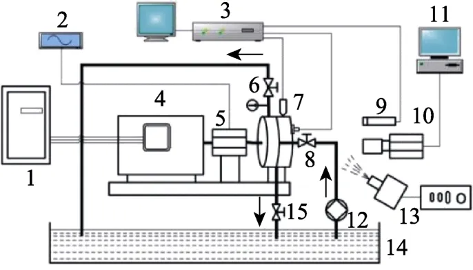
图2 液力减速器空化试验系统示意图Fig.2 Diagram of cavitation experimental system of hydraulic retarder
本文对不同工况下的内部流态、振动加速度和外声场噪声进行了同步采集和数据处理。高速摄影系统由高速相机、多功能相机台架、两个LED灯和MSTUDIO软件等构成,如图3a所示。高速相机采用美国IDT公司生产的YSLM型高速摄影相机,最大拍摄速率为256 000帧/s,能够充分保证对空泡动态特性的捕捉。由于泵轮是金属叶轮,单个LED灯会使拍摄区域产生局部阴影,为确保拍摄区域充分打光,在减速器斜前方 45°布置两个 LED灯。振动加速度传感器采用美国 PBC公司生产的INV9822A型ICP加速度传感器,在后盖板两两相互垂直的3个方向上布置测点,如图3b所示。外声场噪声的测量采用INV9206型声压传感器,传感器布置在减速器正前方1 m的位置,如图3c所示。驱动电机采用皖南三相异步电机,额定转速1 500 r/min,最大转速2 000 r/min,转动惯量 0.02 kg·m2。变频器采用三星公司生产的F700变频器,对电机进行变频调速。采用INV3020C高性能数据采集系统,单台采集系统可达 104通道,最高采样频率102.4 kHz,并对振动、噪声等非定常信号的同步采集后进行数据的时域和频域分析。
为真实反映非定常瞬态信号,需要设置合适的采样频率以保证采集信号对原始信号的真实还原。采样频率过高会发生信号的混叠;采样频率过低则会导致无法捕捉到特征信号,使得采集信号失真。根据奈奎斯特理论,只有采样频率需高于分析频率 2~4倍,才能把数字信号还原成为原来的信号。本文主要研究 0~5 kHz频段范围内空化对振动噪声信号影响规律,为保证信号真实性及高分辨率特性,本文采样频率设置为12.8 kHz,采样时间30 s。
监督责任不够明晰。监督必须要承担责任,不然监督可有可无。但在实践当中,纪检监察人员严格执行制度却经常被贴上不愿担责、缺乏担当的标签,究其原因,是制度规定不够明晰,对监督失职、渎职行为虽然有处罚规定,处罚也很严厉,但依据怎样的标准来定性却较为笼统,被监督部门往往以“出了问题还是我们担责,又不会追你们的责”为由来搪塞;比如招投标承办部门只在开标前通知纪检部门参与监督,是不是做到了事前报告;这时候不监督是失职,监督了怕违规,参与还是不参与,责任如何界定;相关制度却没有明确规定,很多时候显得左右为难。
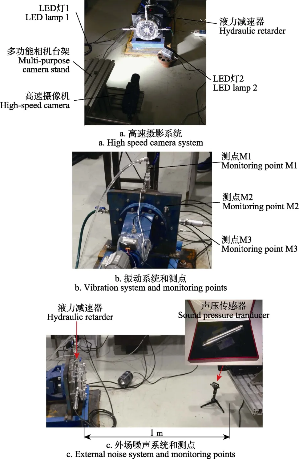
图3 液力减速器空化试验系统测点分布图Fig.3 Distribution of measuring points of cavitation experimental system for hydraulic retarder
1.3 试验设计
考虑到强度问题,采用降低腔内工作压力的方法使其在运行过程中产生空化现象,通过调节增压泵出口阀控制腔内初始压力p,使初始压力p按照0.10、0.08、0.06、0.04、0.03、0.02和0.01 MPa依次降低。对液力减速器在800~1 100 r/min各工况下不同压力运行时内部空化流场进行观测,发现在800~1 100 r/min转速下,仅1 100r/min时,随压力的降低能够观测到空化从无到有直至严重空化的整个过程。因此选择1 100 r/min工况作为分析工况,并对各传感器调零。试验过程中,使液力减速器保持全充液状态且温度恒定。
2 试验结果分析
2.1 空化前后内流场对比
图4为n=1 100 r/min工况,初始压力从0.1 MPa降低到0.01 MPa过程中通过高速摄影捕捉到的涡轮内部流态。可以看出,随着压力从0.1 MPa下降到0.04 MPa,泵轮背面靠近外缘位置最先出现空泡,随着压力继续降低,空泡逐渐占据整个流道。通过高速摄影能够识别出液力减速器空化未发生(p>0.04 MPa)、空化初生(p=0.04 MPa)和空化严重(p=0.01 MPa)等空化形态,为分析空化前后振动噪声特性的变化提供依据。图4f、4g为空化初生及严重空化状态下不同时刻单个流道内流场空泡分布。
2.2 空化前后振动特性对比
图5为n=1 100 r/min工况,初始压力从0.1 MPa降低到0.01 MPa过程中振动加速度幅值的变化情况。可以看出,初始压力从0.1 MPa降低到0.01 MPa的过程中,振动加速度呈现先增大后减小的趋势。测点位置不同,振动大小存在差异,M2测点的振动最为剧烈,M1和M3测点的振动加速度幅值较为接近。由此可知液力减速器运行时,从泵轮流出的液流对涡轮的作用力主要为轴向的冲击力,作用于叶片上的力则要小得多。在空化初生时会出现振动激增的现象,随着空化程度进一步加剧,振动反而减小。
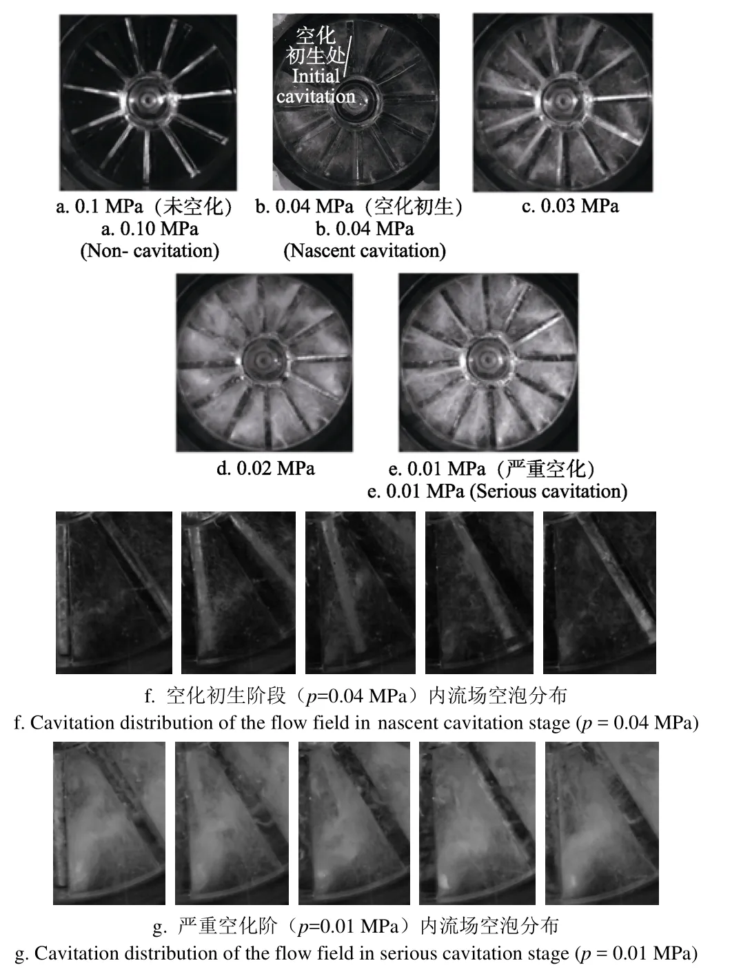
图4 不同初始压力下涡轮内部流场高速摄影图Fig.4 High-speed photogram of turbine internal flow field at different initial pressure conditions
选取3个代表性的空化阶段(未空化0.10 MPa、空化初生0.04 MPa和严重空化0.01 MPa),对3个测点的振动加速度信号在0~5 000 Hz频段内进行频域分析。图6给出了对振动加速度进行FFT变换后的频谱曲线。其中,振动加速度级计算公式为
式中La为振动加速度级,dB;a为振动加速度幅值,mm/s2;a0为基准加速度,取a0=10-6mm/s2。
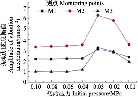
图5 不同初始压力下不同测点振动加速度幅值变化Fig.5 Amplitude of vibration acceleration at different initial pressures of different monitoring points
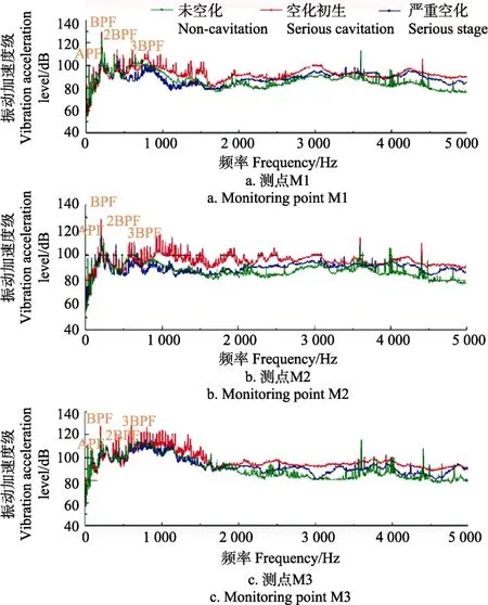
图6 不同空化阶段各测点振动加速度级Fig.6 Vibration acceleration level of different monitoring points at different cavitation stage
由图6可以发现,3个测点的振动加速度频谱曲线趋势基本一致,每个测点的最大值都出现在叶片通过频率(BPF)处。0~2 000 Hz频带内,各测点在各个空化阶段均显示出明显的轴频和叶频及其倍频特征,说明在低频带旋转泵轮和静止壳体间动静干涉作用仍然是引起液力减速器振动的主要原因。各空化阶段振动加速度级之间的差异较小,说明0~2 000 Hz频带不适合作为空化监测的特征频带。2 000~3 000 Hz频带内,空化各阶段的振动加速度级显示出明显差异,空化初生和严重空化阶段的振动加速度级明显大于未空化阶段,各测点均有10 dB左右的增加。3 000~4 000 Hz频带内,各空化阶段振动频谱曲线相互交错,规律不明显。4 000~5 000 Hz频带内,各空化阶段振动加速度级之间的相对差异逐渐增大,空化初生的振动加速度声压级最大,严重空化阶段次之,未空化阶段最小。由此可见,空化前后2 000~3 000 Hz和4 000~5 000 Hz频带振动加速度级的变化明显,可以作为液力减速器空化监测的特征频带。
2.3 空化前后噪声特性对比
图7为n=1 100 r/min工况,初始压力从0.1 MPa降低到0.01 MPa过程中的外场噪声总声压级变化。
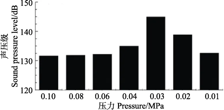
图7 不同工作压力下液力减速器外场噪声总声压级值Fig.7 External sound pressure level of hydraulic retarder at different working pressures
可以看出,空化初生阶段(p=0.04 MPa),噪声声压级明显升高,这是由于空泡产生并迅速破裂的过程中,30%~50%的空泡势能转变为声能。严重空化阶段(p=0.10 MPa)噪声声压级相对于空化初生阶段要小,但略大于未空化阶段(p>0.04 MPa),这是由于此阶段的空泡产生后又在下游低压区进一步扩大,辐射出声能相比于空化初生阶段要小的多。由于总声压级值易受某些突出声压值的影响,从而使得整个声压级增加,无法体现空化对各频段噪声影响规律,因此,需要对信号进一步处理。
将3个典型空化阶段(未空化p=0.10 MPa、空化初生p=0.04 MPa和严重空化p=0.01 MPa)的声压信号进行FFT变换,并对声压级信号进行A计权处理,得到符合人耳听觉的各阶段的声压级(Sound pressure level,SPL)频谱曲线,如图8所示。从图8的声压分布来看,噪声的能量主要集中在0~1 000 Hz频带,声压级随着频率的增大均呈现减小的趋势。
未空化阶段(p=0.10 MPa),0~1 000 Hz频带内,轴频、叶频及其倍频出现峰值,说明在低频带旋转泵轮和静止壳体间动静干涉作用仍然是引起液力减速器噪声的主要原因。1 000 Hz~5 000 Hz频带内,声压级随着频率的升高逐渐降低,呈现宽带谱特性。
空化初生阶段(p=0.04 MPa),主频信号与未空化阶段特性信号基本相同,主要差异体现在 300~500 Hz及1 000~2 000 Hz频带声压级相对未空化阶段呈现上升趋势。造成两个频带声压级上升的原因可能是空泡产生又迅速溃灭所引起结构振动产生的噪声所引起的。
严重空化阶段(p=0.01 MPa),叶频的低倍协频上升,而高倍协频被淹没在宽频信号中。一方面由于空化加剧使气泡增多并发展成气泡团,从而阻塞动静干涉脉动向下游传播,使叶频为主的特征变得不明显,而轴频分量得以突出。另一方面,空泡溃灭会造成低频段的压力波动及高频段的压力脉冲,不同体积空泡群溃灭,使得低频部分的频率分布更加复杂;由于脉冲辐射频率不同,因此造成1 000~5 000 Hz频带出现多峰值特征,在频谱图上体现为宽频。
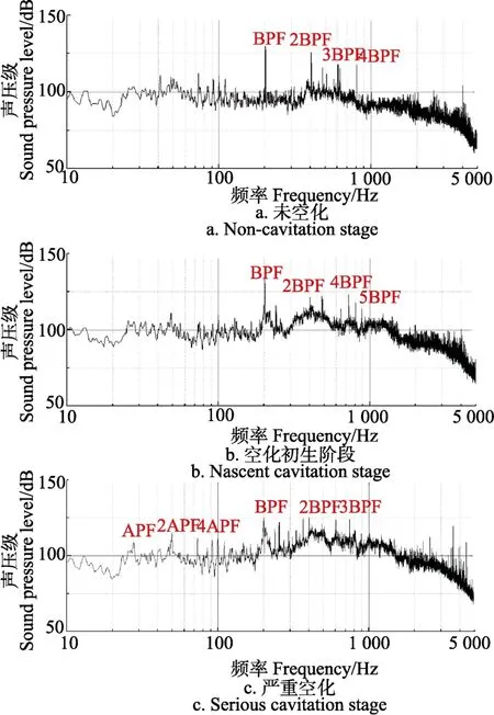
图8 不同空化阶段噪声频谱图(对数坐标)Fig.8 Noise spectrum at different cavitation stage(logarithmic coordinate)
为分析空化对各频段噪声贡献量,将数据进行倍频程分析,得到倍频程谱如图9所示。
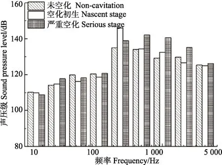
图9 不同空化阶段噪声倍频程谱图Fig.9 Octave noise spectrum at different cavitation stage
可以看出,未空化阶段及空化初生阶段声压级峰值出现在中心频率为250 Hz频带,说明此时动静干涉作用是主要噪声源。严重空化阶段声压级峰值频带较多,因为空化诱导噪声成分所占比重在此阶段上升明显,流动诱导噪声比例相对减小。此外,空化的发生与发展对0~100 Hz低频段基本无影响;100 Hz~1 000 Hz的中频段,空化后噪声信号相比未空化阶段略有升高;1 000 Hz~5 000 Hz高频段,噪声信号随空化的加剧而升高。
3 结 论
1)根据高速摄影拍摄得到的内流场空泡分布结果将整个空化过程分为未空化(初始压力大于0.04 MPa)、空化初生(初始压力等于0.04 MPa)和空化严重(初始压力等于0.01 MPa)等3各阶段。
2)不同测点振动加速度存在较大差异,其中轴向振级高于径向振级。所有测点振动均随空化的发展呈现先增大后减小的趋势,且不同空化阶段在振级频谱体现的频段有所差异,其中0~2 000 Hz及4 000~5 000 Hz频带对空化的发展更加敏感。
3)噪声总声压级随空化呈现先增大后减小的趋势,且不同空化阶段对各频段贡献量不同。空化对0~100 Hz低频段噪声影响很小;0~1 000 Hz中频段声压级随空化的发展呈现先增后减趋势;1 000~5 000 Hz高频信号随空化诱导噪声比重的增加和流动诱导噪声比重的减小呈现不断增大的趋势。
[1] 刘成晔. 汽车辅助制动装置发展综述[J]. 中国安全科学学报,2008,18(1):105-111.Liu Chengye. Review on development of auxiliary braking set of automobiles[J]. China Safety Science Journal, 2008,18(1): 105-111. (in Chinese with English abstract)
[2] 严军,何仁. 液力缓速器叶片变角度的缓速性能分析[J].农业机械学报,2009,40(4):206-209.Yan Jun, He Ren. Performance analysis for hydraulic retarder with different vanes[J]. Transactions of the Chinese Society for Agricultural Machinery, 2009, 40(4): 206-209.(in Chinese with English abstract)
[3] Cooney T J, Mowatt J E. Development of a hydraulic retarder for the allison AT545R transmission[J]. Sae Transactions,1995, 104: 503-51.
[4] 黄榕清,吴磊,邵建华. 汽车液力缓速器的原理及应用[J].汽车电器,2006(11):6-8.Huang Rongqing, Wu Lei, Shao Jianhua. Principle and application of vehicle hydraulic retarder[J]. Automotive Appliances, 2006(11): 6-8.(in Chinese with English abstract)
[5] 郭刘洋,杜明刚. CFD为基的液力减速器结构优化仿真[J].现代制造工程,2009(1):104-106.Guo Liuyang, Du Minggang. Configuration optimizing simulation of vehicle hydrodynamic retarder based on CFD technology[J]. Modern Manufacturing Engineering, 2009(1):104-106. (in Chinese with English abstract)
[6] 袁丹青,陈向阳,白滨,等. 水力机械空化空蚀问题的研究进展[J]. 排灌机械工程学报,2009,27(4):269-272.Yuan Danqing, Chen Xiangyang, Bai Bin, et al. Research progress of cavitation and ersion in hydraulic machinery[J].Journal of Drainage and Irrigation Machinery Engineering,2009, 27(4): 269-272.(in Chinese with English abstract)
[7] 段向阳,王永生,苏永生. 水力机械空化(汽蚀)监测研究综述[J]. 水泵技术,2008(5):1-6.Duan Xiangyang, Wang Yongsheng, Su Yongsheng. Review on monitoring of cavitation of hydraulic machinery[J]. Pump Technology, 2008(5): 1-6.(in Chinese with English abstract)
[8] 康灿,张贵峰,李利婷. 直叶片液力减速器内部流场及空化性能研究[J]. 机械设计与制造,2016(11):92-96.Kang Can, Zhang Guifeng, Li Liting. Internal flows and cavitation performance of a hydraulic retarder equipped with straight blades[J]. Machinery Design and Manufacture,2016(11): 92-96. (in Chinese with English abstract)
[9] 董亮,肖佳伟,明加意,等. 液力减速器模型空化特性数值模拟及试验研究[J]. 排灌机械工程学报,2017,35(1):1-5.Dong Liang, Xiao Jiawei, Ming Jiayi, et al. Numerical simulation and experimental study on cavitation behavior of hydraulic retarder model[J]. Journal of Drainage and Irrigation Machinery Engineering, 2017, 35(1): 1-5. (in Chinese with English abstract)
[10] 肖佳伟. 液力减速器空化特性试验及分析[D]. 镇江:江苏大学,2016.Xiao Jiawei. Experimental Investigation and Analysis on Cavitation of Hydraulic Retarder[D]. Zhenjiang: Jiangsu University, 2016. (in Chinese with English abstract)
[11] 魏巍,李慧渊,邹波,等. 液力减速器制动性能及其两相流分析方法研究[J]. 北京理工大学学报,2010,30(11):1281-1284.Wei Wei, Li Huiyang, Zou Bo, et al. Study on braking performance and analysis of two-phase flow in vehicular hydraulic retarder[J]. Transactions of Beijing Institute of Technology, 2010, 30(11): 1281-1284. (in Chinese with English abstract)
[12] 李雪松. 车辆液力减速器三维流场分析与特性计算[D].长春:吉林大学,2006.Li Xuesong. Three dimensional Flow Field Analysis and Characteristic Calculation of Vehicle Hydraulic Reducer[D].Changchun: Jilin University, 2006. (in Chinese with English abstract)
[13] 严军. 大功率液力减速器设计与制动力矩控制算法研究[D]. 武汉:武汉理工大学,2010.Yan Jun. Research on Design of High Power Hydraulic Reducer and Braking Torque Control Algorithm[D]. Wuhan:Wuhan University of Technology, 2010. (in Chinese with English abstract)
[14] 李慧渊,望运虎,宋振川,等. 温度和出口压力对液力减速器制动力矩的影响机理研究[J]. 车辆与动力技术,2016(1):24-28.Li Huiyuan, Wang Yunhu, Song Zhenchuan, et al. Study of influence mechanism of temperature and outlet pressure on braking torque of hydraulic retarder[J]. Vehicle and Power Technology, 2016(1): 24-28. (in Chinese with English abstract)
[15] 褚亚旭,刘春宝,马文星. 液力耦合器三维瞬态流场大涡模拟与特性预测[J]. 农业机械学报,2008,39(10):169-173.Chu Yaxu, Liu Chunbao, Ma Wenxing. Large eddy simulation of the 3-D transient flow field in hydrodynamic coupling and characteristics prediction[J]. Transactions of the Chinese Society for Agricultural Machinery, 2008, 39(10):169-173.(in Chinese with English abstract)
[16] 张建生,吕青,孙传东,等. 高速摄影技术对水中气泡运动规律的研究[J]. 光子学报,2000,29(10):952-955.Zhang Jiangsheng, Lv Qing, Sun Chuandong, et al. The moment of air bubbles in water by use of high speed photography[J]. Acta Photonica Sinica, 2000, 29(10): 952-955. (in Chinese with English abstract)
[17] 马大猷. 噪声与振动控制工程手册[M]. 北京:机械工业出版社,2002.
[18] 师汉民,黄其柏. 机械振动系统[M]. 武汉:华中科技大学出版社,2013.
[19] 庞剑,谌刚,何华. 汽车噪声与振动[M]. 北京:北京理工大学出版社,2006.
[20] 张鹏瑞,杨智刚. 一种旋转机械振动信号的有效消噪方法[J]. 测控技术,2015,34(8):45-48.Zhang Pengrui, Yang Zhigang. An improved signal denoising method in mechanical fault diagnosis[J]. Measurement and Control Technology, 2015, 34(8): 45-48. (in Chinese with English abstract)
[21] 张小飞,王茁,周有鹏. 超声检测中的噪声处理[J]. 无损检测,2002,24(5):200-202.Zhang Xiaofei, Wang Zhuo, Zhou Youpeng. Noise processing in ultrasonic testing[J]. Nondestructive Testing,2002, 24(5): 200-202. (in Chinese with English abstract)
[22] Robinette D L. Optimizing 12 volt start-stop for conventional powertrains[J]. Sae International Journal of Engines, 2011,4(1): 850-860.
[23] Robinette D L, Wehrwein D. Automatic transmission gear ratio optimization and monte carlo simulation of fuel consumption with parasitic loss uncertainty[J]. Jcms Journal of Common Market Studies, 2015, 8(1): 307-330.
[24] Arakeri V H. Cavitation inception[J]. Sadhana, 1979, 2(2):149-177.
[25] Kowalski D, Anderson C, Blough J. Cavitation detection in automotive torque converters using nearfield acoustical measurements[C]//SAE 2005 Noise and Vibration Conference and Exhibition. 2005: 3668-3678.
[26] Kowalski D, Anderson C, Blough J. Cavitation prediction in automotive torque converters[C]//SAE 2005 Noise and Vibration Conference and Exhibition. 2005: 135-141.
[27] Watanabe S, Otani R, Kunimoto S, et al. Vibration characteristics due to cavitation in stator element of automotive torque converter at stall condition[C]//ASME 2012 Fluids Engineering Division Summer Meeting Collocated with the ASME 2012 Heat Transfer Summer Conference and the ASME 2012, International Conference on Nanochannels, Microchannels, and Minichannels. 2012:535-541.
[28] 袁哲,马文星,卢秀泉,等. 液力减速器动态制动性能预测分析[J]. 吉林大学学报(工),2013,43(增刊 1):160-164.Yuan Zhe, Ma Wenxing, Lu Xiuquan, et al. Dynamic braking performance prediction and analysis of hydrodynamic retarder[J]. Journal of Jilin University (Engineering and Technology Edition), 2013, 43(Supp.1): 160-164. (in Chinese with English abstract)
[29] 王峰,闫清东,马越,等. 基于CFD技术的液力减速器性能预测研究[J]. 系统仿真学报,2007,19(6):1390-1392.Wang Feng, Yan Qingdong, Ma Yue, et al. Prediction and analysis on hydraulic retarder performance based on CFD technology[J]. Journal of System Simulation, 2007, 19(6):1390-1392.(in Chinese with English abstract)
[30] 柴博森,王玉建,刘春宝,等. 基于粒子图像测速技术的液力变矩器涡轮内流场测试与分析[J]. 农业工程学报,2015,31(12):92-98.Chai Bosen, Wang Yujian, Liu Chunbao, et al.Test and analysis of internal flow field in turbine of hydrodynamic torque converter based on particle image velocimetry[J].Transaction of the Chinese Society of Agricultural Engineering(Transactions of the CSAE), 2015, 31(12): 92-98.(in Chinese with English abstract)
[31] 徐礼超,侯学明,基于典型工况的装载机发动机与液力变矩器匹配[J]. 农业工程学报,2015,31(7):80-84.Xu Lichao, Hou Xueming. Power matching on loader engine and hydraulic torque converter based on typical operating conditions[J].Transaction of the Chinese Society of Agricultural Engineering(Transactions of the CSAE), 2015,31(7): 80-84.(in Chinese with English abstract)
[32] 王勇,刘厚林,袁寿其,等. 离心泵非设计工况空化振动噪声的试验测试[J]. 农业工程学报,2012,28(2):35-38.Wang Yong, Liu Houlin, Yuan Shouqi, et al. Experimental testing on cavitation vibration and noise of centrifugal pumps under off-design conditions[J]. Journal of Drainage and Irrigation Machinery Engineering(Transactions of the CSAE),2012, 28(2):35-38.(in Chinese with English abstract)
[33] 刘忠,邹淑云,李志鹏,等. 离心泵空化状态下声发射信号的小波能量特征[J]. 农业工程学报,2015,31(8):99-103.Liu Zhong, Zou Shuyun, Li Zhipeng, et al. Wavelet energy features of acoustic emission signals under centrifugal pump cavitation conditions[J]. Journal of Drainage and Irrigation Machinery Engineering(Transactions of the CSAE), 2015,31(8): 99-103.
Change mechanism of vibration and noise characteristics before and after cavitation in hydraulic retarder
Dong Liang,Zhao Yuqi,Xiao Jiawei,Liu Houlin
(Research Center of Fluid Machinery Engineering and Technology, Jiangsu University, Zhenjiang212013,China)
In the hydraulic braking, the hydraulic reducer is often used in conjunction with other braking methods, which are used in the vehicle auxiliary brake. It is not transmission component, but the energy-saving component which works in the braking conditions. The use of hydraulic reducer in vehicles can effectively control the driving speed, ensure traffic safety, and increase the stability of the vehicle operation and comfort of driving. At braking of high speed device or large rotational inertia device, the inside of hydraulic reducer will cause cavitation, and the braking performance is reduced with temperature increment. The cavitation of hydraulic system can cause vibrating and produce lots of noise. In order to study the vibration and noise characteristics before and after cavitation in hydraulic retarder, a cavitation and vibration noise test bench was built based on the INV3020 data collection system and the high-speed photography system, which realized the synchronous acquisition for the performance parameters and vibration noise signals. The hydraulic reducer model was made of plexiglass material for the convenience of high speed photography. Firstly, by adjusting the opening of inlet and outlet valve of hydraulic retarder, the internal working pressure of the hydraulic reducer is controlled under several different conditions. The frequency converter is regulated to adjust the motor operating voltage, so that the pump speed of the impeller can be stable in several operation conditions. Combined with high-speed photography experiment, the accurate experiment condition was obtained for cavitation nascent stage, and the vibration and noise signals were measured before and after the cavitation in hydraulic retarder by using acceleration sensor and sound pressure sensor. The experimental results show that, the entire cavitation process can be divided into non-cavitation stage, nascent cavitation stage and serious cavitation stage based on the high-speed photography results. At nascent cavitation stage, the bubble first appeares at the back of the impeller close to the outer edge when the rotation speed of the impeller equals to 1 100 r/min and the inlet pressure equals to 0.04 MPa. As the pressure continues to decrease, the flow channel is gradually occupied by the bubbles, and it goes into serious cavitation stage. The vibration mainly occurs in radial direction of monitoring point, while there is no difference of vibration intensity between the 2 monitoring points. At nascent cavitation stage, the amplitude of vibration acceleration increases sharply, and with the degree of cavitation is further intensified, the amplitude of vibration acceleration is reduced. The change of the cavitation acceleration level of 2 000-3 000 Hz and 4 000-5 000 Hz bands before and after cavitation is obvious, which can be used as the characteristic frequency band of hydraulic reducer. For noise signal, the total sound pressure level in nascent cavitation stage is larger than that in severe cavitation stage, and the minimum value appears in the non-cavitation stage. The maximum value of noise signal is concentrated on blade passing frequency and its harmonic frequencies, which indicates that static and horizontal interference between the rotating pump wheel and the stationary shell in the low frequency band is still the main cause to the noise of the hydraulic reducer. In the 0-100 Hz low frequency band, there is no obvious relationship between sound pressure level and cavitation stages. In the 100-1 000 Hz middle frequency band, compared with serious cavitation stage and non-cavitation stage,the noise signal in nascent cavitation stage is slightly increased. Because the proportion of cavitation-induced vibration and noise components increases significantly at this stage, and the proportion of flow induced vibration noise is relatively reduced.In the high frequency range of 1 000-5 000 Hz, as the proportion of radiation noise signal of bubble burst increases, the serious cavitation stage shows the maximum amplitude of acoustic pressure value, the nascent cavitation stage takes the second place,and the non-cavitation stage shows the minimum value. The study could provide a reference for the study of cavitation vibration and noise of hydraulic retarder and the design method of it.
hydraulic equipment; cavitation; vibrations; noise; hydraulic retarder
10.11975/j.issn.1002-6819.2017.14.008
TH132.46
A
1002-6819(2017)-14-0056-07
董 亮,赵宇琪,肖佳伟,刘厚林. 液力减速器空化前后振动及噪声特性变化机理[J]. 农业工程学报,2017,33(14):56-62.
10.11975/j.issn.1002-6819.2017.14.008 http://www.tcsae.org
Dong Liang, Zhao Yuqi, Xiao Jiawei, Liu Houlin. Change mechanism of vibration and noise characteristics before and after cavitation in hydraulic retarder[J]. Transactions of the Chinese Society of Agricultural Engineering (Transactions of the CSAE),2017, 33(14): 56-62. (in Chinese with English abstract)
doi:10.11975/j.issn.1002-6819.2017.14.008 http://www.tcsae.org
2016-11-02
2017-06-05
国家自然科学基金(51509111);江苏省产学研联合创新资金资助项目(BY2016072-01);过程装备与控制工程四川省高校重点试验室开放基金资助项目(GK201403);中国博士后科学基金资助项目(2015M581734,2017M611721);西华大学流体及动力机械教育部重点试验室开放课题资助项目(szjj2015—017,szjj2017-094);江苏高校优势学科建设工程资助项目(PAPD)
董 亮,男,副研究员。镇江 江苏大学流体机械工程技术研究中心,212013。Email:dongliang@ujs.edu.cn
猜你喜欢
科技与创新(2022年21期)2022-11-04
水泵技术(2021年5期)2021-12-31
上海交通大学学报(2021年8期)2021-09-02
数字海洋与水下攻防(2021年2期)2021-05-08
电脑知识与技术·经验技巧(2020年5期)2020-06-22
中国医学物理学杂志(2020年3期)2020-04-06
航天电子对抗(2019年4期)2019-06-02
传动技术(2017年4期)2018-01-26
舰船科学技术(2017年11期)2017-11-27
船海工程(2015年4期)2016-01-05