残膜捡拾压缩车及其作业工艺设计与试验
刘进宝,郑 炫,赵 岩,陈学庚,刘兴爱,葛士林
残膜捡拾压缩车及其作业工艺设计与试验
刘进宝1,郑 炫2※,赵 岩2,陈学庚2,刘兴爱1,葛士林3
(1. 新疆科神农业装备科技开发股份有限公司,石河子 832000;2. 新疆农垦科学院机械装备研究所,石河子 832000;3. 中国农业大学工学院,北京 100083)
为解决残膜回收时捡拾率低、机具集膜箱存储量小、机械化作业过程不连续等问题,研制了一种棉田残膜捡拾压缩车,该机主要由清杂机构、捡膜机构、脱膜输送机构、压缩机构等组成,可同时完成残膜杂质分离、残膜捡拾、脱膜输送和压缩作业。通过对样机关键作业部件的设计,确定了清杂辊、捡膜机构和脱膜输送装置的结构及工作参数,并分析了机具作业过程。样机分别在3种残膜分段回收工艺:搂集—捡压、秸秆还田—搂集—捡压、秸秆还田—捡压中进行试验,田间试验表明,机具作业速度在5~7 km/h,清杂辊转速为240 r/min,捡膜机构转速为90 r/min,脱膜辊转速为1 000 r/min时,在回收工艺一搂膜距离≤40 m,回收工艺二搂膜距离≤60 m时,膜堆残膜捡拾率大于80%,清杂率大于78%;在回收工艺三中,棉杆残留根茬高度≤80 mm时,未集堆地表残膜捡拾率达到88.21%,机具缠膜率小于2%,机具可一次性捡拾压缩回收8 hm2田间残膜。
农业机械;设计;试验;残膜;回收工艺;清理杂质;膜堆捡拾;液压压缩
0 引 言
目前残膜回收机具主要由残膜捡拾机构和卸膜输送机构组成,按捡拾机构的结构形式可分为弹齿式、搂齿式、链耙式、气吸式等结构,其中搂齿式结构能将地膜搂集呈堆状,搂集残膜时将部分棉杆、棉叶等杂质一同搂起,因此其清杂能力差;弹齿式结构采用伸缩齿相对于滚筒往复伸缩的运动形式,具有较好的清杂能力;链耙式结构采用排列密度大的耙齿,其捡拾率较高,但残膜缠绕较为严重[1-5]。
残膜回收机按有无集膜箱又可分为:残膜捡拾回收机和搂膜集条机2种机型,其中,残膜捡拾回收机设置有集膜箱,利用捡膜机构捡拾田间残膜,利用中间脱膜输送装置,将捡拾残膜输送至集膜箱,一次性实现残膜捡拾装箱作业[6-10]。此类机型由于整机尺寸的限制,集膜箱容积有限,由于残膜堆积时呈虚状,导致集膜箱残膜装载量有限,作业过程需要频繁停机卸膜,限制了作业效率[11-15]。搂膜集条机无集膜箱,作业时利用弧形弹齿将地表残膜搂起,弧形弹齿可临时存储一定量的残膜,作业一段距离后利用卸膜杆将残膜卸落至地表,通过搂集作业后,形成集条成堆的地表膜堆[16-19],然后通过人工将集条膜堆中残膜与杂质分离,并清理装车;此类机型无法一次性将残膜回收,需要进行膜堆二次捡拾回收作业[20]。
目前残膜回收普遍存在的问题是,由于机具无集膜箱或集膜箱装载量小的限制,不仅降低机具作业效率,而且使田间存在大量的回收膜堆,目前还未研制出较为成熟的捡拾膜堆的机具,作业过程需要消耗大量人力物力,并且膜堆无法及时回收处理容易造成二次污染;回收后的残膜含有大量的棉杆、叶、杂土等,导致回收后的残膜杂质含有量较高,给回收残膜再利用带来了很大的不便[15]。针对上述问题,设计了配合残膜分段回收作业模式的一种棉田残膜捡拾压缩车,以期为高效的残膜回收机械化连续作业提供参考。
1 残膜捡拾压缩车整机结构设计
1.1 总体结构
棉田残膜捡拾压缩车是根据残膜分段回收工艺模式,为残膜清杂捡拾压缩作业环节设计的一种新机型,残膜捡拾压缩车主要由机架、清杂机构、捡膜机构,脱膜输送机构、残膜压缩机构和液压控制系统组成。清杂机构主要由清杂辊组成,捡膜机构由伸缩杆齿滚筒式捡拾机构组成,清杂辊在圆周上按规律排列有多组弧形弹齿,在清杂辊的后上方安装有伸缩杆齿滚筒式捡拾机构。在伸缩杆齿滚筒式捡拾机构的上方安装有脱膜输送机构,脱膜输送机构主要由脱膜辊、脱膜平皮带、护罩组成。残膜压缩机构主要由压缩液压缸、推膜板、压缩箱体、卸膜后门、后门开关液压缸和翻斗液压缸组成。残膜捡拾压缩车整机结构如图1所示。

1. 牵引架 2. 齿轮箱 3. 机架 4. 清杂辊 5. 偏心滚筒 6. 杆齿 7. 防护罩 8. 压缩液压缸 9. 推膜板 10. 地轮 11. 翻斗液压缸 12. 压缩箱体 13. 卸膜后门 14. 后门开关液压缸 15. 脱膜辊护罩 16. 脱膜辊
1.2 工作原理
机具作业时,由拖拉机牵引前进,由清杂辊4将膜堆向前上方挑起,将残膜从茎秆、杂土等杂质中挑出,一部分残膜被挑至杂质表层,另一部分残膜被清杂辊弹齿挑起,这时转动的伸缩杆齿6将地表残膜捡起,同时还可以将弹齿上的残膜挑起,通过伸缩杆齿6与偏心滚筒5的圆周运动配合,在偏心滚筒5的顶部将杆齿6上的残膜脱落至滚筒表面,然后由脱膜平皮带将残膜刮起,通过脱膜辊16的回转运动与脱膜辊护罩15的共同作用下,将残膜运送至残膜压缩箱体12中;当残膜落入压缩箱体12后,由往复动作的压缩液压缸8推动楔形推膜板9将残膜压缩至箱体后方;通过连续的残膜捡拾、杂质清理、脱膜、压缩作业,最后将残膜装满压缩箱体后,后门开关液压缸14动作,将卸膜后门13打开,然后翻斗液压缸11动作,将压缩后的残膜卸出。
1.3 主要技术参数
根据残膜回收国家标准和棉花种植农艺要求,并结合新疆平作区棉花种植特点,残膜捡拾压缩车主要技术指标如下表1所示。
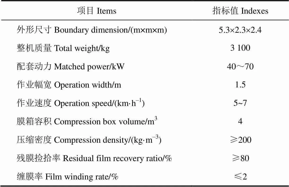
表1 主要技术指标
2 关键机构设计及分析
2.1 清杂机构设计
由于集条后的膜堆中含有大量的秸秆、杂土等杂质,大量残膜被杂质覆盖,在残膜捡拾之前,需要先将残膜从杂质中分离,因此设计了一种清杂辊,其结构如图2所示。

1. 挡盘 2. 弹齿 3. 钢管 4. 半轴
1. Back plate 2.Spring tooth 3. Steel pipe 4. Axles
注:为弹齿末端回转半径,mm;为弹齿安装折弯角,(°);为机具作业速度,m·s–1;1为清杂辊转动角速度,rad·s–1。
Note:is the radius of gyration at the end of spring tooth, mm;is the install bend angle of spring tooth, (°);is the machine forward speed, m·s–1;1is the angular velocity of the separating roller, rad·s–1.
图2 清杂辊结构示意图
Fig.2 Structure diagram of separating impurity roller
清杂辊圆周表面排列有多组弹齿,机具前进作业时,通过清杂辊的回转运动,弹齿将膜堆中残膜与杂质一同挑起,由于离心力的作用,杂土、秸秆等杂质被清杂辊离心抛出,而质量较轻的残膜被挑起时,一部分残膜掉落在地面,另一部分残膜缠绕在弹齿上。
杂质被弹齿挑起时应做离心运动,满足如下条件:

式中0为杂质质量,kg;为弹齿末端回转半径,mm;1为清杂辊转动角速度,rad/s;0为杂质与弹齿之间的摩擦力,N;为弹齿安装折弯角,(°)。
其中摩擦力0=00sin,0为杂质与弹齿的摩擦因数,取0.43。得出

经过清理杂质试验验证,弹齿安装折弯角 取20°,清杂效果较好,通过测量集条膜堆尺寸,膜堆高度在150~400 mm之间,因此弹齿末端回转半径取225 mm,得出1>6.88 rad/s。
2.2 捡膜机构设计
残膜捡拾机构主要包括滚筒、偏心支撑座、连杆、杆齿总成,其结构如图3所示。杆齿与转轴盘构成杆齿总成,并通过连杆与滚筒相连,偏心支撑座将滚筒与杆齿总成铰接在机架上,当杆齿在做回转运动时,杆齿可相对于滚筒上的栅缝进行往复伸缩,当杆齿伸出滚筒栅缝最长时进行挑膜作业,当杆齿伸出滚筒栅缝长度不断减小时,滚筒将杆齿上附着的残膜逐渐脱至杆齿齿尖处,最后将残膜附着在滚筒外表面上,然后进行下一道脱膜输送作业,达到了既能捡拾残膜又能将残膜脱落的作用。
2.2.1 杆齿排列结构设计
杆齿总成作为捡拾残膜的主要部件,由6组杆齿圆周均布排列在转轴盘上组成,通过卡子将杆齿方钢固定在转轴盘上,为了减小杆齿入土挑膜时的阻力,将杆齿末端切为尖角状。

1. 偏心支撑座 2. 滚筒法兰盘 3. 连杆销 4. 连杆 5. 转轴盘 6. 滚筒
杆齿与清杂辊弹齿安装时采取交错排列,排列方式见图4,其中在圆周方向,杆齿设为6组,弹齿设为4组,杆齿中心处于相邻两弹齿中心线上,杆齿与相邻弹齿之间的间隙为2,设置杆齿与弹齿排列间距相等,即2=0.51。为保证杆齿与弹齿的强度,清杂辊弹齿受力较大,设计1=16 mm,2=25 mm,使两者既不相互干涉,又能满足捡拾分布的密度,杆齿外圆面与弹齿外圆面安装间隙距离取12 mm,得出排列间距1=32.5 mm。

1. 杆齿 2. 弹齿
1. Pole teeth 2. Spring teeth
注:1为相邻弹齿排列间距,mm;2为杆齿与相邻弹齿之间的安装间隙,mm;1为杆齿直径,mm;2为弹齿直径,mm。
Note:1is the spacing between adjacent spring teeth, mm;2is the installation clearance between pole teeth and adjacent spring teeth, mm;1is diameter of pole teeth, mm;2is diameter of spring teeth, mm.
图4 杆齿与弹齿排列
Fig.4 Arrangement of pole teeth and spring teeth
2.2.2 滚筒结构设计与运动分析
滚筒结构主要由滚筒和滚筒法兰盘组成,机构简图如图5所示。
滚筒由2.5 mm厚的钢板卷制而成,滚筒表面圆周均布排列有6组栅缝,滚筒法兰盘为幅板型,幅板将滚筒法兰盘分成3等份,滚筒法兰盘幅板上设有连杆铰接安装孔。杆齿伸入滚筒栅缝中与之配合。由于滚筒中心与杆齿轴中心之间存在偏心距,两者之间再次用连杆相连,连杆中心距与偏心距相等。
简化杆齿滚筒运动模型,其中点为杆齿转轴中心,1点为滚筒轴心,点为连杆1与杆齿转轴盘2的铰接点,点为连杆1与滚筒3的铰接点,点为杆齿末端,杆齿滚筒机构由平行四杆机构演变而来,短杆1作为机架、长杆作为主动曲柄的平行四杆机构运动。

1. 滚筒 2. 滚筒法兰盘 3. 杆齿 4. 转轴盘 5. 连杆
1. Roller 2. Roller flange 3. Pole teeth 4. Rotation shaft flange 5.Connecting rod
注:点为杆齿转轴中心,1点为滚筒轴心,点为连杆与杆齿转轴盘的铰接点,点为连杆与滚筒的铰接点,点为杆齿末端。为连杆力,N;1为铰接点距滚筒圆心的半径,mm;为偏心距,mm;为滚筒法兰盘幅板等分角,(°);为连杆传动角,(°);v为点线速度,m·s–1;2为杆齿转动角速度,rad·s–1。
Note:is the center of rotation shaft;1is the center of roller;is the hinge point of the rotation shaft flange and the connecting rod;is the hinge point of the connecting rod and the roller;is the end of pole teeth;is connecting rod force, N;1is the radius of the hinge pointfrom the center of the roller, mm;is eccentricity, mm;is the roller flange plate equal angle, (°);is the connecting rod drive angle, (°);vis thepoint line speed, m·s–1;2is the angular velocity of the pole teeth, rad·s–1.
图5 杆齿运动示意图
Fig.5 Structure diagram of pole teeth motion
机构转动时,拖拉机动力输出轴通过齿轮箱、皮带传动,带动转轴盘转动,杆齿转轴盘作为主动件,通过连杆带动滚筒一起转动,由杆齿通过沿着连杆的方向传递的力,在滚筒上产生一个主动力矩,从而驱动滚筒转动。6组杆齿与3等分的滚筒法兰盘幅板通过2组连杆连接,2组连杆安装位置如图5中所示。其中,连杆产生的主动力矩为:

两组连杆产生的主动力矩值为:

式中为主动力矩,N·m;为连杆力,N;1为滚筒法兰盘连杆铰接点距滚筒圆心的半径,mm;为滚筒法兰盘幅板等分角,取120°;为连杆传动角,(°)。
从式中可以看出,当其中一组连杆11传动角=90°时,连杆处于机构的死点位置,连杆驱动的有效分力为零,此时由另一组连杆提供有效分力

当两组连杆传动角≠90°时,由两组连杆共同提供有效分力,使机构稳定可靠做回转运动。
2.2.3 杆齿捡膜及防缠绕参数确定
机具以图6a中速度方向作业时,清杂辊以1的角速度顺时针转动,杆齿以2的角速度逆时针转动。
清杂辊弹齿末端在坐标系中的运动方程为:

式中为机具作业速度,m/s;为杆齿中心与清杂辊中心水平距离,取490 mm;为杆齿中心与清杂辊中心竖直距离,取245 mm;为机具前进作业时间,s。
注:点为杆齿转轴中心,2点为清杂辊轴中心,为杆齿与清杂辊弹齿转动的重叠区域,为杆齿末端运动轨迹与2连线的交点;0为转轴盘半径,mm;为杆齿末端回转半径,mm;为杆齿长度,mm;为杆齿中心与清杂辊中心水平距离,mm;为杆齿中心与清杂辊中心竖直距离,mm;为杆齿接触地面时弹齿入土深度,mm;为杆齿安装角,(°);v为杆齿末端在点相对弹齿的运动速度,m·s–1。
Note:is the center of rotation shaft;2is the center of separating roller;is the overlapping region of the pole teeth and the rotation of the spring teeth of the cleaning compound roller;is the intersection of the end of the pole teeth and the2line;0is the radius of rotation shaft flange, mm;is the radius of gyration at the end of pole teeth, mm;is the length of pole teeth, mm;is the horizontal distance between the center of the pole teeth and the spring teeth, mm;is the erect distance between the center of the pole teeth and the spring teeth, mm;is depth into earth of spring teeth when pole teeth touching ground, mm;is the installation angle of pole teeth, (°);vis the speed at which the end of the pole teeth at the a point relative to the projectile, m·s–1.
图6 杆齿与弹齿挑膜运动示意图
Fig.6 Structure diagram of sketch map of film movement of pole teeth and spring teeth
杆齿末端运动轨迹方程为:
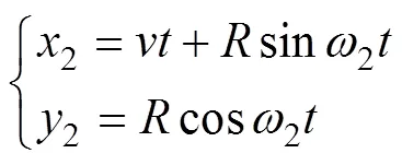
式中2为杆齿转动角速度,rad/s;为杆齿末端回转半径,mm。
其中

式中0为杆齿转轴盘半径,取210 mm;为杆齿长度,取245 mm;为杆齿安装角,取45°。计算得出=427.5 mm。
同时为保证清杂与捡拾充分,避免出现漏挑区域,清杂辊弹齿和杆齿末端运动轨迹应呈余摆线,即速度比满足以下条件:

式中1为清杂辊速度比,2为杆齿速度比。
综合考虑作业效率和效果,取1=3,2=2,根据机具作业速度范围在5~7 km/h,为保证机具捡拾率及机具运行的稳定性,经过多次试验论证,得到机具最大作业速度为1.9 m/s,因此取=1.9 m/s,取=225 mm,=427.5 mm,计算得出清杂辊转速1=25.3 rad/s,杆齿转速2=8.9 rad/s,通过MATLAB软件绘制杆齿末端和弹齿末端的运动轨迹曲线,如图6b所示。
清杂辊弹齿和杆齿的安装位置相对于地面高度不相同,当杆齿末端接触到地面时,清杂辊弹齿需入土深度=45 mm。由于膜堆底部存有大量残膜,为保证清杂与捡拾充分,作业时杆齿入土深度为10 mm,则清杂辊弹齿入土深度为55 mm。
清杂辊弹齿在清杂膜堆时,容易使残膜缠绕在弹齿以及清杂辊上,为了使清杂辊上缠绕的残膜能被及时回收,设置伸缩杆齿与清杂辊相互配合作业,图中阴影区域为杆齿与清杂辊弹齿转动的重叠区域,在此区域中,杆齿可将接触到清杂辊弹齿上缠绕的残膜。
在重叠区域中,杆齿中心与清杂辊中心2连心线的切线方向,杆齿末端线速度与清杂辊弹齿末端线速度同向,在接近清杂辊弹齿根部相交点处的相对速度v为:

将=490 mm,=245 mm代入公式(10),计算得出v=0.8 m/s。杆齿和清杂辊之间具有相对运动速度,因此可将清杂辊弹齿上缠绕的残膜挑起,有效防止清杂辊缠膜现象。
根据转速与角速度关系:

最终确定清杂辊转速1=301/p=240 r/min,杆齿转速2=302/p=90 r/min。
2.3 脱膜输送机构的设计
在捡膜机构的正上方设置有脱膜输送机构,脱膜输送机构采用类似风机结构[21-22],主要由脱膜辊和脱膜护罩组成,脱膜辊圆周表面均布排列有8组脱膜叶片,脱膜叶片采用宽度=150 mm的平皮带,脱膜滚筒采用半径2=120 mm、壁厚为3 mm的钢管,其中钢管外壁设置有8组直径为60 mm的气流通道孔,脱膜护罩正下方为开口状,为残膜输送的入口,脱膜护罩斜上方开口为残膜输送出口,结构如图7所示。
2.3.1 脱膜输送过程分析
1)刮膜提升作业:通过脱膜叶片的刮取作用,将捡拾滚筒上的残膜刮起,残膜临时存储在相邻脱膜叶片之间,通过脱膜辊的转动将残膜运送至脱膜辊上方,作业过程中脱膜辊转向与捡膜机构转向相反。
2)抛送作业:当残膜在脱膜辊上方,脱膜辊将残膜抛出,同时脱膜辊转动产生的气流,使其做离心运动,在抛送作业时,残膜沿着脱膜叶片向外运动,假设残膜集中在脱膜叶片质点处,受力情况须满足:

式中c为离心力,N;w为气流作用力,N;为脱膜叶片摩擦力,N;为脱膜叶片工作偏转角,(°);为气流作用力与脱膜叶片夹角,(°)。
其中

式中3为脱膜辊角速度,rad/s;t为脱膜叶片末端距中心半径,取270 mm。
1. 脱膜护罩 2. 脱膜叶片 3. 脱膜滚筒 4. 仿形弹簧 5. 定位板 6. 缓冲弹簧 7. 机架 8. 捡膜机构 9. 弹簧螺杆 10. 定位螺母
1. Residual film shedding shield 2. Residual film removing blade 3. Residual film shedding roller 4. Copying spring 5. Locating plate 6. Buffer spring 7. Frame 8. Pickup mechanism 9. Spring screw 10. Locating nut
注:3点为脱膜滚筒轴心,4为脱膜护罩与机架铰接点;为脱膜叶片宽度,mm;2为脱膜滚筒半径,mm;为脱膜护罩与滚筒间隙,mm;为脱膜叶片工作偏转角,(°);为气流作用力与脱膜叶片夹角,(°);为残膜质量,kg;3为脱膜辊角速度,rad·s–1;c为离心力,N;w为气流作用力,N;为脱膜叶片摩擦力,N;n为脱膜叶片对残膜的支持力,N。
Note:3is the center of the residual film shedding roller;4is the residual film shedding shield and frame hinge joint;is the width of the residual film removing blade, mm;2is the radius of residual film shedding roller, mm;is clearance between residual film shedding shield and roller, mm;is residual film removing blade work deflection angle, (°);is the angle between the air force and the residual film removing blade, (°);is residual film quality, kg;3is the angular velocity of the residual film shedding roller, rad·s–1;cis centrifugal force, N;wis the air force, N;is the frictional force of the residual film removing blade, N;nis supporting force of residual film removing blade on residual film, N.
图7 脱膜机构结构示意图
Fig.7 Structure diagram of residual film shedding mechanism
其中脱膜叶片摩擦力

式中为脱膜叶片摩擦因数,取0.6。得出:

本设计中,为保证脱膜顺利不产生拥堵,假设在不考虑气流作用力w的情况下,残膜依靠离心力便可被脱膜辊抛出,即满足:

当=20°,得出脱膜辊角速度3>6.5 rad/s。
3)气流输送作业:当残膜被抛出脱膜叶片后,残膜被抛出的瞬间具有离心运动速度v,并且依靠风机产生的气体流速v将其从脱膜护罩中吹出,残膜脱离脱膜叶片时瞬时合速度为v与v的矢量和:

其中残膜悬浮速度在0.3~1.2 m/s之间[23],短茎秆悬浮速度在2.8~4.4 m/s之间[24-25]。由于残膜在抛送过程中含有少量的短茎秆,因此气体流速v须大于残膜和短茎秆的悬浮速度,才能将残膜吹送出脱膜护罩。通过试验测得当脱膜辊转速为1 000 r/min时,出口的风速接近10 m/s,转速满足脱膜作业要求。
2.3.2 防拥堵结构设计
由于残膜在搂集成堆时,堆放尺寸及含杂率不规律,使得捡拾时喂入量不均匀,当捡拾量过大时,脱膜护罩与捡拾滚筒之间容易产生拥堵,因此将脱膜护罩右端与机架采用铰接连接方式,脱膜护罩左端焊接有定位板,定位板上设有弹簧螺杆伸缩孔,定位板与机架之间设有2组弹簧,弹簧套装在弹簧螺杆上,上端为仿形弹簧,当拥堵残膜对脱膜护罩施加载荷时,脱膜护罩相对于铰接点以较小角度向上转动,此时仿形弹簧被压缩,脱膜护罩与捡拾滚筒之间间隙变大,拥堵的残膜及杂质从间隙间被抛出,当拥堵消除后,仿形弹簧复位,脱膜护罩恢复初始状态,下端缓冲弹簧起到缓冲作用,其中间隙初始值为25 mm。
2.4 压缩系统设计
压缩系统主要由压缩箱体,液压系统和控制系统组成,其中液压回路如图8a所示,液压回路包括压缩液压缸、翻斗液压缸和后门液压缸三组独立动作的液压缸。

1. 液压油箱 2. 液压泵 3. 溢流阀 4. 单向阀 5. 减压阀 6~8. 三位四通电磁换向阀 9~10. 双向液压锁 11~14. 二位二通电磁换向阀 15~17. 节流阀 18. 压力继电器19. 压缩液压缸 20. 翻斗液压缸 21. 后门液压缸
每组液压缸由2个参数相同的缸体组成,通过电磁换向阀控制回路液压油的流向,在翻斗液压缸回路和后门液压缸回路中分别设置双向液压锁,防止液压缸伸出后由于外界较大载荷迫使液压缸缩回现象。由于翻斗液压缸和后门液压缸在动作时,所受载荷在不断变化,为避免机构之间产生激烈的碰撞,在两组液压缸回路中设置了2条回路,其中第一条回路通过二位二通电磁换向阀控制通断,回路液压流量不变;第二条回路由二位二通电磁换向阀和节流阀组成,由二位二通电磁换向阀控制回路通断,由节流阀降低回路液压流量,从而控制液压缸动作速度;机构运动时,在冲击较小的区间,采用第一条回路,在冲击较大的区间,采用第二条调速回路,降低动作速度,避免机构产生较大冲击。
其中压缩液压缸动作时,由行程开关SQ1和压力继电器共同控制往复压缩动作,在压缩过程中,当压缩液压缸进油腔的压力达到减压阀5设定值时,压缩缸停止压缩作业,并且有杆腔进行缩回,当有杆腔缩回至行程开关SQ1处时,电磁换向阀1换向,进行下一次压缩作业。液压回路中电磁换向阀的换向动作由PLC控制,采用西门子S7-200型PLC进行控制,其中输入信号由按钮、行程开关和压力继电器产生,输出信号控制液压回路的电磁换向阀。PLC输入输出分配如图8b所示。
3 残膜捡拾田间试验
3.1 试验条件
2016年10月5日~2016年10月15日在新疆生产建设兵团石河子149团进行田间试验,作业地块为秋后棉花收获后的平作区棉田,回收地膜厚度为0.008 mm聚乙烯农用地膜,残膜捡拾压缩车配套动力为雷沃754轮式拖拉机。
3.2 试验方法
为了使残膜回收实现机械化连续作业,样机分别在3种分段回收工艺:①搂集—捡压、②秸秆还田—搂集—捡压、③秸秆还田—捡压中进行试验,在试验中配合其他机具实现残膜机械化分段连续作业回收,作业模式如图9所示。

1. 棉秆 2. 集条残膜
1. Cotton stalk 2. Collection strip residual film
注:为集条膜堆幅宽,m;为一次搂膜作业距离,m;向为棉花种行方向;、向为垂直于棉花种行的方向。
Note:is residual film stack width, m;is once gathering up the residual film distance, m;is cotton planting direction;、is perpendicular to the cotton planting direction
图9 残膜回收工艺模式简图
Fig.9 Diagram of residual film recycling method
3.2.1 回收工艺一:搂集—捡压
作业过程:秸秆还田机开设卸膜集条区®立杆搂膜机搂膜集条®残膜捡拾压缩车捡拾膜堆;作业特点:首先利用秸秆还田机在垂直于棉花种行的方向上,每间隔一段距离开设一定宽度的卸膜区,其次立杆搂膜机进行田间搂膜作业,并且将搂起的残膜堆积在卸膜区域,最后利用残膜捡拾压缩车将卸膜区的集条残膜进行清杂捡拾装箱压缩作业。目前,在残膜回收机市场中,立杆搂膜机占有率较大,回收工艺一技术应用推广较为成熟。
为了便于各回收工序之间高效衔接作业,应满足以下参数要求:①集条膜堆幅宽小于残膜捡拾压缩车作业幅宽;②一次搂膜作业距离不宜过大,避免集条膜堆含杂率高导致集条残膜的膜堆尺寸过大;③秸秆还田机作业幅宽应与集条膜堆区域幅宽相近。
3.2.2 回收工艺二:秸秆还田—搂集—捡压
作业过程:秸秆还田残膜集条机作业®残膜捡拾压缩车捡拾膜堆;作业特点:首先利用秸秆还田残膜集条联合作业机作业,棉杆粉碎还田作业的同时利用搂膜机构将残膜搂集成条成堆,然后利用残膜捡拾压缩车将集条残膜进行清杂捡拾装箱压缩作业。近年来秸秆还田残膜回收联合作业技术发展较快,随着联合作业技术的不断成熟[23-26],回收工艺二正逐步推广使用。
3.2.3 回收工艺三:秸秆还田—捡压
作业过程:秸秆还田机进行秸秆还田作业/拔棉杆机回收棉杆作业®残膜捡拾压缩车捡拾田间地表残膜;作业特点:首先利用秸秆还田机将棉杆粉碎还田,或者利用拔棉杆回收机回收棉杆,然后利用残膜捡拾压缩车将秸秆还田后地表残膜清杂捡拾装箱压缩作业,两道工序作业方向均沿着棉花种行方向。随着棉杆造纸技术的不断提升、电厂燃料的需求、以及秸秆还田技术的日益成熟[27-30],回收工艺三具有较好的应用前景。
3.2.4 试验参数测定方法
在作业工艺一和作业工艺二的前期搂膜作业时,搂膜作业距离依次设置为30、40、50、60、70 m,然后利用残膜捡拾压缩车捡拾集条残膜膜堆,测得膜堆相关数据,以及残膜捡拾压缩车作业的相关数据。
在5组搂膜作业距离中,随机选取测试区,每一组选取5个测试点,测试点的作业面积相等,分别称质量每个测试点的膜堆总质量、回收后残膜毛质量,并且对回收后的残膜和未收回残膜进行清洗称质量,测得其净质量。其中,清杂率、膜堆质量、膜堆中所含残膜质量c、回收残膜毛质量1、回收残膜净质量2之间的关系为:

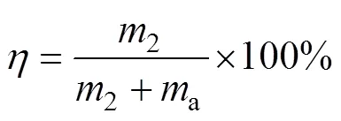
捡拾率、回收残膜净质量2、未收回残膜净质量a之间的关系为:
其中一定面积内集条膜堆中残膜净质量所占占有率为:

根据作业对象可分为两大类,第一类为回收膜堆残膜,即工艺一和工艺二,前2种回收工艺根据搂膜距离做比较试验;第二类为回收秸秆还田后未集堆残膜,即为回收工艺三,因此不考虑膜堆残膜占有率与清杂率,主要测其捡拾率、装载量和压缩效果。
3.3 试验结果
分段回收作业配套机具选用科神公司研制的应用较为广泛的1LM-6.6型立杆搂膜机(收膜部件为弧形弹齿,作业方式为单一搂集作业,作业幅宽为6.6 m),和4JLM- 2.0型秸秆还田弹齿搂膜机(收膜部件为弧形弹齿,作业方式为秸秆还田残膜搂集联合作业,作业幅宽为2 m)进行前期搂膜集条作业,2种方式搂集后的膜堆堆放尺寸、杂质含量均不相同,搂膜作业结果如图10所示。

a. 立杆搂膜集条膜堆 a. Setting heap of gathering up residual film before cotton stalk smashingb. 秸秆还田弹齿搂膜集条膜堆 b. Setting heap of gathering up residual film after cotton stalk smashing
残膜捡拾压缩车分别捡拾立杆搂膜作业的膜堆和秸秆还田搂膜联合作业的膜堆,即残膜捡拾压缩车应用于回收工艺一和回收工艺二中,捡拾集条膜堆残膜试验数据统计结果如表2所示。

表2 残膜捡拾压缩车回收工艺一、二试验数据
由试验结果可以看出,集条膜堆中残膜占有率随着搂膜距离的增加在不断减小,残膜捡拾压缩车的捡拾率和清杂率也相应的下降。其中,回收工艺一中,当搂膜距离≤40 m时,膜堆残膜捡拾率大于80%;回收工艺二中,当搂膜距离≤60 m时,膜堆残膜捡拾率大于80%,达到捡拾作业要求。因此,为指导当前作业规范,回收工艺一中立杆搂膜距离设定为40 m,残膜捡拾压缩车捡拾率为82.96%,回收工艺二中打杆搂膜距离设定为60 m,残膜捡拾压缩车捡拾率为81.91%。
在回收工艺三的试验中,利用秸秆还田机将棉杆粉碎还田后,根茬高度≤80 mm。秸秆还田后田间地膜含杂率较低,装满压缩膜箱(装载量为1 200 kg,压缩密度为300 kg/m3)可一次性捡拾8 hm2田间地膜,残膜捡拾率为88.21%,捡拾作业效果对比如图11。机具缠膜现象主要发生在清杂辊处,由于捡膜机构设置了防缠绕作业参数,据3种回收工艺试验效果,机具缠膜率均小于2%。
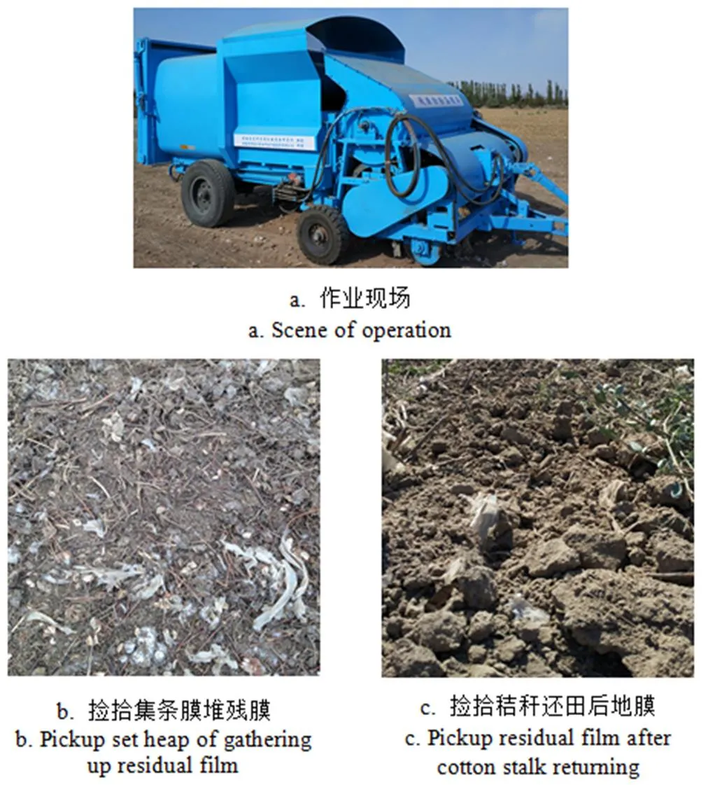
注:图11b中,含杂率高,捡拾率低;图11c,含杂率低,捡拾率高。
在实际压缩作业时,压缩液压缸压缩速度对残膜压缩影响较为明显,压缩不及时导致残膜在压缩膜箱入口处出现拥堵。因此,根据残膜捡拾喂入量与压缩时间相匹配的关系,进行了多次试验,机具作业速度为1.9 m/s时,设置压缩缸往复压缩一次用时20 s,能保证压缩作业顺畅。回收残膜杂质含量对装载量及压缩密度有较大的影响,当压缩缸压力一定,杂质含量较低时,残膜容易松散,压缩缸在退回阶段,残膜易产生回落,因此还需进一步研究压缩压力与杂质含量对残膜压缩密度的影响。
由试验结果看出,前期搂膜作业的含杂率对膜堆残膜捡拾率有明显的影响,因此,后续研究需进一步提高机具的清杂能力。机具实际作业时,地表并非绝对平整,由于播种、中耕、植保、采收等机具作业时对地面的压力,导致棉田地表有部分凹陷,残膜捡拾压缩车的随地仿形能力较为局限,因此在凹陷处残膜捡拾率较低,还需改进机具随地仿形能力,进一步提高残膜捡拾率和清杂率。
4 结论与讨论
1)为了配合残膜分段回收作业模式,研制了一种残膜捡拾压缩车,通过对清杂机构、捡膜机构、脱膜输送机构及压缩系统进行设计,计算各关键部件的结构及工作参数,该机能较好的适应3种新型残膜回收工艺作业。
2)提出了适合秋季棉田残膜回收的3种回收工艺方法,分别为:①秸秆还田机切碎棉秆开设卸膜区®立杆搂膜机搂膜集条®残膜捡拾压缩车捡拾膜堆残膜;②秸秆还田残膜集条机作业®残膜捡拾压缩车捡拾膜堆残膜;③秸秆还田机进行秸秆还田作业或拔棉杆机回收棉杆作业®残膜捡拾压缩车捡拾田间地表残膜。3种回收工艺中,各回收工序环节可高效有序的衔接作业,能够较好的解决秋后棉田机械化回收的难题。
3)样机田间残膜回收率试验表明,回收工艺三效果最佳,残膜捡拾压缩车捡拾秸秆还田后的地表残膜,回收率可达88.21%,残膜回收作业工序较少,作业效率较高。为指导当前作业规范,回收工艺一中立杆搂膜距离设定为40 m,残膜捡拾压缩车捡拾率为82.96%,回收工艺二中打杆搂膜距离设定为60 m,残膜捡拾压缩车捡拾率为81.91%。通过样机试验测试,各项性能试验指标均满足设计要求。
在新提出的回收工艺中,膜堆杂质含量情况直接影响残膜捡拾压缩车的捡拾率及清杂率,因此在各作业环节中需要进一步提升机具的清杂能力,进一步提高残膜捡拾率。
[1] 侯书林,胡三媛,孔建铭,等. 国内残膜回收机研究的现状[J]. 农业工程学报,2002,18(3):186-190.Hou Shulin, Hu Sanyuan, Kong Jianming, et al. Present situation of research on plastic film residue collector in China[J]. Transactions of the Chinese Society of Agricultural Engineering (Transactions of the CSAE), 2002, 18(3): 186-190. (In Chinese with English abstract)
[2] 张佳喜,谢建华,薛党勤,等. 国内外地膜应用及回收装备的发展现状[J]. 农机化研究,2013,35(12):237-240. Zhang Jiaxi, Xie Jianhua, Xue Dangqin, et al. Development status of applying plastic film and the residue plastic filming film collecting machine at domestic and overseas[J]. Journal of Agricultural Mechanization Research, 2013, 35(12): 237-240. (In Chinese with English abstract)
[3] 那明君,董欣,侯书林,等. 残膜回收机主要工作部件的研究[J]. 农业工程学报,1999,15(2):112-115. Na Mingjun, Dong Xin, Hou Shulin, et al. Research on main components of the machine for retrieving the used plastic film after harvesting[J]. Transactions of the Chinese Society of Agricultural Engineering (Transactions of the CSAE), 1999, 15(2): 112-115. (in Chinese with English abstract)
[4] 李斌,王吉奎,蒋蓓. 新疆棉区残膜污染及其治理技术[J].农机化研究,2012,34(5):228-232. Li Bin, Wang Jikui, Jiang Bei. The plastic film pollution and treatment technology in Xinjiang cotton area[J]. Journal of Agricultural Mechanization Research, 2012, 34(5): 228-232. (in Chinese with English abstract)
[5] 张佳,张宇涛,董黎明,等. 国内残膜回收机械研究现状及发展趋势[J]. 农业科技与装备,2014,36(4):29-30,33.Zhang Jia, Zhang Yutao, Dong Liming, et al. Domestic residual film recovery machine research status and development trend[J]. Agricultural Science & Technologyand Equipment, 2014, 36(4): 29-30, 33. (in Chinese with English abstract)
[6] 徐弘博,胡志超,吴峰,等. 残膜回收收膜部件研析[J]. 农机化研究,2016,38(8):242-249. Xu Hongbo, Hu Zhichao, Wu Feng, et al. Study on the collecting component of plastic film residue collector[J]. Journal of Agricultural Mechanization Research, 2016, 38(8): 242-249. (in Chinese with English abstract)
[7] 谢建华. 垄作残膜捡拾及脱卸装置的研究[D]. 北京:中国农业大学,2014. Xie Jianhua. Study on Pick-up and Unloading Device for Residual Plastic Film of Bed Planting[D]. Beijing: China Agricultural University, 2014. (in Chinese with English abstract)
[8] 陈发,史建新,王学农,等. 弧型齿残膜捡拾滚筒捡膜的机理[J]. 农业机械学报,2006,37(6):36-41. Chen Fa, Shi Jianxin, Wang Xuenong, et al. Study on collecting principle of arc-type tooth roller for collecting plastic residue[J]. Transactions of the Chinese Society for Agricultural Machinery, 2006, 37(6): 36-41. (in Chinese with English abstract)
[9] 谢建华,侯书林,付宇,等. 残膜回收机弹齿式拾膜机构运动分析与试验[J]. 农业机械学报,2013,44(增刊1):94-99. Xie Jianhua, Hou Shulin, Fu Yu, et al. Motion analysis and experiment on spring-tooth mulching plastic film collector[J]. Transactions of the Chinese Society for Agricultural Machinery, 2013, 44(Supp.1): 94-99. (in Chinese with English abstract)
[10] 胡凯,王吉奎,李斌,等. 棉秆粉碎还田与残膜回收联合作业机研制与试验[J]. 农业工程学报,2013,29(19):24-32.Hu Kai, Wang Jikui, Li Bin, et al. Development and experiment of combined operation machine for cotton straw chopping and plastic film collecting[J]. Transactions of the Chinese Society of Agricultural Engineering (Transactions of the CSAE), 2013, 29(19): 24-32. (in Chinese with English abstract)
[11] 王吉奎,付威,王卫兵,等. SMS-1500型秸秆粉碎与残膜回收机的设计[J]. 农业工程学报,2011,27(7):168-172. Wang Jikui, Fu Wei, Wang Weibing, et al. Design of SMS- 1500 type straw chopping and plastic film residue collecting machine[J]. Transactions of the Chinese Society of Agricultural Engineering (Transactions of the CSAE), 2011, 27(7): 168-172. (in Chinese with English abstract)
[12] 王学农,史建新,郭俊先,等. 悬挂式棉秆粉碎还田搂膜机搂膜机构的设计与试验研究[J]. 农业工程学报,2008,24(1):135-140.Wang Xuenong, Shi Jianxin, Guo Junxian, et al. Experimental study and design on film raking mechanism of hanging film raker withcotton-stalk crushing and returning to field[J]. Transactions of the Chinese Society of Agricultural Engineering (Transactions of the CSAE), 2008, 24(1): 135-140. (in Chinese with English abstract)
[13] 何义川,王序俭,王吉亮,等. 4SZ-3.0型收膜整地联合作业机的设计与试验[J]. 甘肃农业大学学报,2013,48(4):149-154.He Yichuan ,Wang Xujian ,Wang Jiliang, et al. Design and experiment of 4SZ-3.0 film collecting combined tillage machine[J]. Journal of Gansu Agricultural University, 2013, 48(4): 149-154. (in Chinese with English abstract)
[14] 张学军. 残膜分离与输送装置的研究[D]. 长春:吉林大学,2007. Zhang Xuejun. Study on Separation and Transport Device for Remnant Plastic Film[D]. Changchun: Jilin University, 2007. (in Chinese with English abstract)
[15] 刘旋峰,张丽,郭兆峰,等. 1SM-1.8(2.0)型牵引式棉田残膜回收机的研制[J]. 新疆农机化,2015,31(3):13-14.
[16] 陈振歆,王金武,牛春亮,等. 弹齿式苗间除草装置关键部件设计与试验[J]. 农业机械学报,2010,41(6):81-86.Chen Zhenxin, Wang Jinwu, Niu Chunliang, et al. Design and experiment of key components trash cultivators working in paddy rice seeding lines[J]. Transactions of the Chinese Society for Agricultural Machinery, 2010, 41(6): 81-86. (in Chinese with English abstract)
[17] 施丽莉,胡志超,顾峰玮,等. 耙齿式垄作花生残膜回收机设计及参数优化[J]. 农业工程学报,2017,33(2):8-15.Shi Lili, Hu Zhichao, Gu Fengwei, et al. Design and parameter optimization on teeth residue plastic film collector of ridged peanut[J]. Transactions of the Chinese Society of Agricultural Engineering (Transactions of the CSAE), 2017, 33(2): 8-15. (in Chinese with English abstract)
[18] 孙兴冻,陈玉龙,罗昕,等. 针对秋后立秆模式的残膜回收机的设计[J]. 农机化研究,2015,37(9):73-76.Sun Xingdong,Chen Yulong, Luo Xin, et al. Design and research of plastic film residue collector used on vertical stem after autumn[J]. Journal of Agricultural Mechanization Research, 2015, 37(9): 73-76. (In Chinese with English abstract)
[19] 于云海,陈学庚,温浩军. 秸秆粉碎与残膜集条联合作业机的研制与试验[J]. 农业工程学报,2016,32(24):1-8.Yu Yunhai, Chen Xuegeng, Wen Haojun. Development and experiment of cotton straw chopping and plastic film collection strip combined machine[J]. Transactions of the Chinese Society of Agricultural Engineering (Transactions of the CSAE), 2016, 32(24): 1-8. (in Chinese with English abstract)
[20] 赵岩,郑炫,周敦兴. 农田残膜捡拾打包联合作业机的研制[J]. 新疆农机化,2015,31(1):6-7.
[21] 胡小钦. 贯流式谷物清选装置设计及性能试验研究[D]. 杭州:浙江理工大学,2012. Hu Xiaoqin. Design and Performance Evaluation of a Cross-Flow Grain Cleaning Device[D]. Hangzhou: ZhejiangSci-Tech University, 2012. (in Chinese with English abstract)
[22] 林亮. 小型轴流式风机通流部件优化设计研究[D]. 南京:东南大学,2015. Lin Liang. Optimization Design of Flow Passage Parts of a Small Axial Fan[D]. Nanjing: Southeast University, 2015. (in Chinese with English abstract)
[23] 李从权. 秸秆粉碎还田及残膜回收联合作业机的关键零部件研究[D]. 乌鲁木齐:新疆农业大学,2007.Li Congquan. The Study of the Key Parts and Key Components of the Field Straw Chopper Work with Film Collecting Machine[D]. Urumqi: Xinjiang Agricultural University, 2007. (in Chinese with English abstract)
[24] 郭文松,坎杂,张若宇,等. 网状滚筒式籽棉残膜分离机物料特性分析[J].农业工程学报,2011,27(增刊2):1-5. Guo Wensong, Kan Za, Zhang Ruoyu, et al. Analysis of material character based on mesh roller-type cotton and film remnant separator[J]. Transactions of the Chinese Society of Agricultural Engineering (Transactions of the CSAE), 2011, 27(Supp.2): 1-5. (in Chinese with English abstract)
[25] 坎杂,郭文松,张若宇,等. 网状滚筒式籽棉残膜分离机的设计[J]. 农业工程学报,2011,27(6):95-99. Kan Za, Guo Wensong, Zhang Ruoyu, et al. Design of mesh roller-type separator for machine- harvested seed cotton and film remnant[J]. Transactions of the Chinese Society of Agricultural Engineering (Transactions of the CSAE), 2011, 27(6): 95-99. (in Chinese with English abstract)
[26] 史建新,陈发,郭俊先,等. 抛送式棉秆粉碎还田机的设计与试验[J]. 农业工程学报,2006,22(3):68-72.Shi Jianxin, Chen Fa, Guo Junxian, et al. Design and experimental research of the field straw chopper with throwing cotton- stalk[J]. Transactions of the Chinese Society of Agricultural Engineering (Transactions of the CSAE), 2006, 22(3): 68-72. (in Chinese with English abstract)
[27] 盛言忠. 揭膜拔秆技术试验分析[J]. 农机具之友,2010,16(7):29-30.Sheng Yanzhong.Experiment and analysis on techniques of removing coating and rocker[J]. Friends of the Agricultural Machinery, 2010, 16(7): 29-30. (In Chinese with English abstract)
[28] 郭振华,史建新,康秀生,等.铲切式拔棉秆阻力分析[J]. 新疆农机化,2008,24(4):9–11.
[29] 陈明江,平英华,曲浩丽,等. 棉秆机械化收获技术与装备现状及发展对策[J]. 中国农机化,2012,29(5):23-26.Chen Mingjiang, Ping Yinghua, Qu Haoli, et al. Status and development countermeasures of mechanized cotton-stalk harvesting technologies and equipments[J]. Chinese Agricultural Mechanization, 2012, 29(5): 23-26. (in Chinese with English abstract)
[30] 姚祖玉,全腊珍,邹运梅,等. 小型棉秆收获机打捆装置的设计与试验[J]. 湖南农业大学学报:自然科学版,2015,41(5):560-564. Yao Zuyu, Quan Lazhen, Zou Yunmei, et al. Design and test of baling mechanism for small-type cotton harvester device[J]. Journal of Hunan Agricultural University :Natural Sciences, 2015, 41(5): 560-564. (in Chinese with English abstract)
刘进宝,郑 炫,赵 岩,陈学庚,刘兴爱,葛士林.残膜捡拾压缩车及其作业工艺设计与试验[J]. 农业工程学报,2017,33(19):17-26. doi:10.11975/j.issn.1002-6819.2017.19.003 http://www.tcsae.org
Liu Jinbao, Zheng Xuan, Zhao Yan, Chen Xuegeng, Liu Xingai, Ge Shilin.Design and experiment of operating process for collecting residual film compacted truck[J]. Transactions of the Chinese Society of Agricultural Engineering (Transactions of the CSAE), 2017, 33(19): 17-26. (in Chinese with English abstract) doi:10.11975/j.issn.1002-6819.2017.19.003 http://www.tcsae.org
Design and experiment of operating process for collecting residual film compacted truck
Liu Jinbao1, Zheng Xuan2※, Zhao Yan2, Chen Xuegeng2, Liu Xingai1, Ge Shilin3
(1.832000,; 2.832000,;3.100083,)
The high impurity content and the residual film loosening have led to the problems that the recovery rate of residual film is low, the machine loading capacity is small, and the mechanized operation process is not continuous. In order to solve these problems, we put forward 3 kinds of recycling models of residual film recovery after cotton harvest, and analyzed the operation process and operating features of these 3 kinds of recycling methods. The first kind of recycling process was as follows: Firstly, the straw returning machine set up the residual film strip; secondly, the heap of the residual film was set before cotton stalk recovery; finally, the truck collecting and compacting residual film picked up the heap of the residual film gathered. For the second kind of recycling process, cotton straw chopping and residual plastic film collection strip combined machine was firstly operated; next, the truck collecting and compacting residual plastic film picked up the heap of the residual film gathered. The third kind of recycling process was as follows: Firstly, straw returning machine operates, or cotton stalk pulling machine operates; secondly, the truck collecting and compacting residual film picked up the surface residual plastic film. A new operation mode was designed for the truck collecting and compacting residual film. The machine consists of impurities separation mechanism, pickup mechanism, residual film shedding mechanism, residual film compression mechanism, and hydraulic control system. Machine can simultaneously complete separation of residual film and impurities, residual film pickup and delivery, and residual film compression. A kind of structure preventing residual film winding was designed, and spring teeth and pole teeth in this structure were in staggered arrangement. The equations of the motion of impurities separation mechanism and pickup mechanism were respectively established, and the process of impurities separation mechanism and pickup mechanism operation was analyzed. The rotational speed of the end of the spring teeth was calculated to be 240 r/min, and the rotational speed of the pole teeth end of the picking mechanism was 90 r/min. The mechanism was designed, which could prevent residual film shedding mechanism from congestion. The operation process of the residual film conveying mechanism was analyzed, and the rotational speed of the end of film removing blade was 1 000 r/min. A kind of electronically controlled hydraulic compression system was designed, and the residual film loading of the compressed film box was improved. Then we examined the capability of the prototype and checked its production functions in field. The size of the heap of the residual film and the proportion of the residual film were recovered in the different distances for the first kind of recovery process model and the second kind of recovery process model. The prototype field experiments showed that, with the increase of the work distance of gathering up the film, the size of the residual film stack was increasing, and the proportion of residual film was decreased obviously. In the case of the same work distance gathering up the residual, the impurity content in the first kind of recycling process was higher than that of the second kind of recycling process, and the recovery rate of the residual film in the first kind of recycling process was lower than that of the second kind of recycling process. The recovery effects of three kinds of recovery processes were compared. The first kind of recovery method included gathering up the residual film before cotton stalk recovery—collecting residual film and compressing, with a work distance of gathering up the film of less than 40 m, and its pickup work was better. The secondary recovery method included gathering up the film after cotton stalk returning—setting heap of the residual film gathered—collecting residual film and compressing, with a work distance of gathering up the film of less than 60 m, and its pickup work was better, with a pickup rate of greater than 80%. The third recovery method included cotton stalk recovery—collecting residual film and compressing, and when the stubble height was less than 80 mm, the collecting rate of residual film reached 88.21%. The truck collecting and compacting residual film could pick up and compress the residue film in 8 hm2field. The rate of film winding was less than 2%. Through compression test, it demonstrated, to ensure the smooth operation of the machine when the operating speed of the machine was 1.9 m/s, the reciprocating compression time of compression cylinder was 20 s; the compression density was up to 300 kg/m3.
agricultural machinery; design; experiments; residual film; recovery method; cleaning out impurities; residual film stack pickup; hydraulic compression
10.11975/j.issn.1002-6819.2017.19.003
S223.5
A
1002-6819(2017)-19-0017-10
2017-03-11
2017-08-04
公益性行业(农业)科研专项经费项目(201503105);兵团重大科技项目(2014AA002-2)。
刘进宝,男,新疆伊犁人,助理研究员,主要从事现代农业机械装备的研究,Email:jinbao1226@126.com
※通信作者:郑 炫,女,江苏徐州人,研究员,主要从事现代农业机械装备的研究。Email:jiazhengxuan@sohu.com。

