A numerical study on heat transfer enhancement and design of a heat exchanger with porous media in continuous hydrothermal flow synthesis system
Pedram Karimi Pour-Fard,Ebrahim Afshari*,Masoud Ziaei-Rad,Shahed Taghian-Dehaghani
Department of Mechanical Engineering,Faculty of Engineering,University of Isfahan,Hezar Jerib Ave.,Isfahan 81746-73441,Iran
1.Introduction
The hydrothermal synthesis method is a system that offers significant advantages in the manufacture of nanoparticle metal oxides and is preferred to traditional synthesis methods[1].Another method,which is developed to overcome the restrictions of hydrothermal reactions,is continuous hydrothermal flow synthesis(CHFS)[2].In this process,using supercritical water instead of organic solvents,results to high quality nanoparticle production.Metal oxides should be rapidly cooled and changed from a slurry state to nanoparticles to prevent the formation of large particles,which reduce the quality of the product.Employing an efficient heat exchanger with a high cooling capability helps to attain this purpose[3].Moreover,devising a method like using porous media in the heat exchanger to enhance the cooling rate leads to smaller required size of the heat exchanger and higher quality of the product[4,5].
Supercritical water is the operating fluid or the solvent in many processes.In the hydrothermal synthesis processes,the reaction rate between the oxidizers and organic materials can be increased by using non-polarorganic compounds in supercritical water[6,7].The oxidation of supercritical water is a high-efficiency process and does not release any environmentally damaging materials[3].This process,known as supercritical water hydrothermal synthesis,is used widely in CHFS systems[8].In recent researches,various analyses have been conducted on CHFS in producing materials such as iron oxide nanoparticles,nanophosphorous-based flame retardant agent and CeO2nanoparticles,which demonstrate a wide range of CHFS applications in contemporary studies[9-11].
CHFS system processes are modeled mathematically and numerically in many researches.Mathematical correlations are used for simulation of supercritical water in CHFS system in some studies[12-15].In addition,CFD modeling is employed to investigate the fluid flow behavior and the heat transfer phenomenon in CHFS systems with new approaches[16].Lichtet al.[17]assessed some semi-empirical correlations for heat transfer coefficients of water at supercritical conditions in a circular and square annular flow channel.A general agreement was observed between their simulated results and those obtained through experimental measurements.They also indicated that the implemented correlations could be applied for both high and low mass velocity tests in the absence of heat transfer reduction.Caiet al.[18]studied numerically the effects of inlet conditions on the cooling rate of the product in a heat exchanger used for CHFS applications.Their results demonstrated that CFD modeling is an effective means for the design optimization of heat exchangers used in CHFS systems.In one of recent studies conducted on CHFS system,Caiet al.[19]simulated a confined jet mixer for nanomaterials in CHFS system to assess fluid flow and heat transfer behaviors in the reactors at different scales.Their results showed that the reactor with laboratory scale had slightly better mixing behavior than the reactor with pilot plant scale.
In addition to above-mentioned works,many studies can also be found in the literatures on heat transfer improvement of heat exchangers by implementing the porous media in different systems.Junco[20]investigated the heat transfer phenomenon in a spherical porous media imbedded in another porous media.Their numerical results demonstrated that the porous media permeability alters the mechanism of heat transfer and the magnitudes of the radial velocity on the surface of the sphere.Ronget al.[21]studied the effect of porous media on heat transfer improvement in internal flow through tubes.They found that adjusting the porous media thickness significantly enhances the heat transfer and the porosity has a small influence on both the flow and the temperature fields,when other parameters are fixed.Wajs and Mikielewicz[22]applied a metallic porous layer on the heat transfer surface of a plate heat exchanger and carried out an experimental assessment on passive heat transfer intensification in the unit.Their investigations revealed the merits of applying such heat exchangers for some fluids and in some flow ranges.Bourantaset al.[23]implemented a computational approach to verify the effects of porous media application on heat transfer in nanofluids.Their results indicated that higher Rayleigh number magnitudes improve the natural convection flows,which leads to the diminution of the heat source temperature.Linet al.[24]numerically employed a porous graphite foam heatexchanger to increase the cooling power and space limitation of vehicle cooling application.They illustrated that this type of cooling applications should be used in vehicles instead of old ones,due to their high thermal performance and low pressure drop.Wanget al.[25]proposed a numerical model to study the hydrodynamic characteristics of a plate- fin heat exchanger(PFHE)through applying the porous media approach.Their results showed that the flow distribution of the heat exchanger is enhanced by using perforated fins or by increasing the fluid dynamic viscosity.
The reviewed studies reveal that although some works have been separately conducted on continuous hydrothermal flow synthesis and porous media application in heat exchangers,no research can be found in the literatures on porous media application(especially partial porous media)in heat exchangers in the CHFS systems.In this paper,the effect of using porous media in a heat exchanger in CHFS system on heat transfer enhancement is investigated numerically.Moreover,numerous numerical simulations are performed to obtain the minimum required length of the porous heat exchanger for different inlet conditions.
In this study, first a computational methodology for modeling of the fluid flow through a heat exchanger in a CHFS system is presented.At this step,the product and the cooling water temperature distributions,as well as the heat transfer coefficients are obtained along the heat exchanger and validated with experimental data.At the second step,a metallic porous media(metal foam)is employed inside the heat exchanger to increase the cooling rate and quality of the product.Then,six different thicknesses of the porous media are examined to obtain the optimum thickness based on the minimum effective length of the heatexchanger.Finally,numerous simulation runs are performed to obtain the minimumrequired length of the porous heatexchanger by changing the inlet temperature and mass flow rate of the product,as well as the mass flow rate of the cooling water.
2.Simulation of the Heat Exchanger
A CFD model is adopted to simulate the CHFS process in the heat exchanger.The heat exchanger length is 530 mm and the inlet and outlet arms have the length of 62 mm.The computational domain at the first stage of the simulation consists of three subdomains:
(1).The stainless steel inner tube(for the product)with a 4.57 mm diameter.
(2).The steel wall between the product and the cooling water with a thickness of 0.89 mm.
(3).The outer tube for the cooling water flow with a 15.75 mm diameter and inlet and outlet arms diameter of 15 mm.
Hot water(at 465 K and 24.1 MPa) flows through the inner tubes,while the cooling water(in flow temperature of 283 K and 0.6 MPa pressure) flows in opposite direction of the product through the shell side.The outer wall of the heat exchanger is assumed to be adiabatic.
In the preliminary simulations,it is assumed that the porous media be installed in the whole volume between the inner and outer tubes.However,the results were not encouraging for this configuration.Hence,a novel configuration is devised in which a porous mantle(with the same thickness as the stainless steel tube)is installed on the outer layer of the inner tube,as shown in Fig.1.This model leads to satisfactory results.
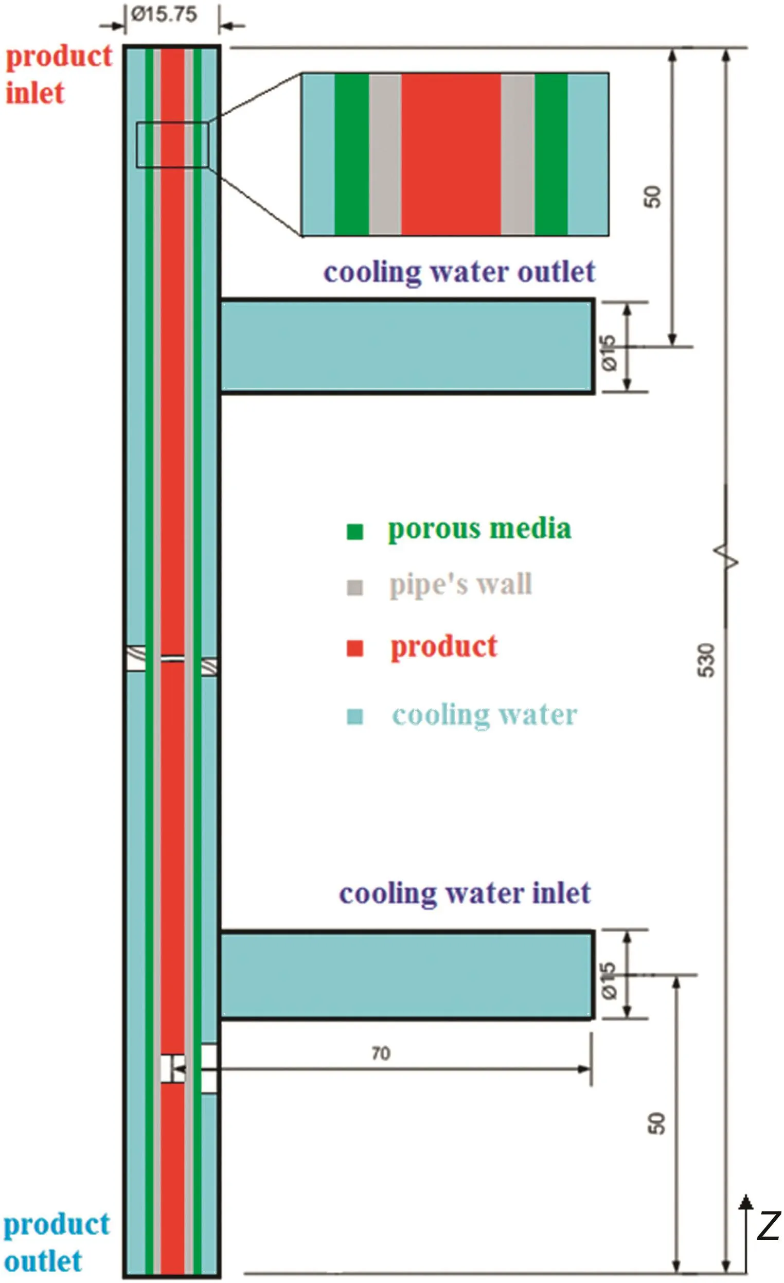
Fig.1.Computational domain for simulation of the heat exchanger.
At the second stage,the computational domain consists of four following subdomains:
(1).The stainless steel inner tube(for the product)with the diameter of 4.57 mm.
(2).The steel wall between the product and the porous media with the thickness of 0.45 mm.
(3).The porous media between the steel wall and cooling water with the thickness of 0.45 mm.
(4).The outer tube for the cooling water flow with 15.75 mm in diameter,and inlet/outlet arms with 15 mm in diameter.
The boundary conditions are considered identical to those of the first stage.
At the next step,six different thicknesses of the porous media are examined to obtain the optimum thickness of the porous media based on the minimum effective length of porous heat exchanger.Table 1 lists six simulation runs corresponding to porous media thicknesses.

Table 1Numerical simulation case studies for obtaining the optimum thickness of the porous medium.
At the final step,36 numerical simulation runs are conducted to obtain the minimum required length of the porous heat exchanger for different inlet conditions,as summarized in Table 2.Three different product and cooling water mass flow rates and four different product inlet temperatures are included,while other variables are kept fixed in the simulations.

Table 2Numerical simulation case studies for obtaining the minimum required length of the porous heat exchanger
It is worth noting that in this study,the permeability is set to 2.5×10⁻⁸m2and the porous media is made of an aluminum alloy and supposed to be homogeneous.
2.1.Mathematical formulation
The governing equations for the fluid flow through the heat exchanger are mass,momentum and energy conservation equations[26],given by:
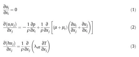
According to the approved capability of two-equationk-ε model for numerical simulation of turbulent flow in heat exchangers[18],this model is chosen for the turbulence simulation in this study.Two additional transport equations are included in the modeling,as follows:

wherekandεare the turbulent kinetic energy and turbulent dissipation rate,respectively.Also,Grepresents the generation of turbulence kinetic energy due to the mean velocity gradients,expressed as:

The four empiricalconstantsσk,σε,Cε1andCε2used in Eqs.(4)and(5)are determined by matching the experimental data for simple turbulent flows.Their typical values are[27]:

After solving Eqs.(1)-(5)and calculatingkand ε,the turbulent viscosity can be obtained by the following correlation:

In the viscosity-affected near-wall region,one-equation model of Wolfstein(a two region model)is employed[28].In this model,the transport equation forkis written as:

and the turbulent viscosity is calculated from the following equation.

In above equations,lεandlμare two length scales with the damping effects in the near wall regions.They are defined as:


The Wolfstein model is adopted to determine the flow characteristics fory+=yρ/μ<200.The computational mesh in near-wall region is refined so that the first computational cell is located aroundy+=5 and the required conditions for the validity of the model are satisfied.
In the analysis ofmomentum equation forporous media,itshould be noted that in porous media with open porosity,the pressure gradient causes the flow to permeate the media.Porous media is modeled using a momentum source for simple homogenous porous media known as Brinkman's equation that is added to the standard fluid flow equations.In this equation(Eq.(12))the first viscous term is the Darcy term and the second viscous term is an inertial loss term[29].

where α is the permeability,Cis the inertial resistance.
In present case,owing to existence of non-reactive contact surface between the fluid and the porous media and high conduction heat transfer coefficient in the turbulent flow,the thermal equilibrium assumption is valid.For simulations in which the thermal equilibrium condition between the flow and the porous media is met,the conduction flux in the porous media uses an effective conductivity and the transient term includes the thermal inertia of the solid region on the media[29]:

whereEfis the total fluid energy,Esis the total solid media energy,ρfis the fluid density,ρsis the solid media density,γ is the porosity of the media,λeffis the effective thermal conductivity of the media,Sfhis the fluid enthalpy source term,Jiis the diffusion flux of speciesi,hiis the sensible enthalpy of speciesiand τ is the average shear-stress tensor.
The effective thermal conductivity in the porous media(λeff),is considered as the volume average of the fluid conductivity and the solid conductivity,given by:

where λfis the thermal conductivity of the fluid phase and λsis the solid media thermal conductivity.Porosity(γ)is defined as the nonsolid or pore-volume fraction of the porous media.
The convection heat transfer coefficients are computed on the outer wall of the inner tube.To calculate the convection heat transfer coefficients,the amount of heat transfer rate in each computational cell(˙Qi)is obtained as follows[18,29,30]:

wherehis the specific enthalpy and˙mis the mass flow rate.Hence,the overall heat transfer coefficient will be:

whereAiis the cross sectional area and ΔTiis the temperature gradient between computational cells along the tube.
2.2.Mesh generation and grid analysis
For the second stage,the computational domain is divided into four subdomains,including the inner tube,the steel wall between the product and the porous media,the porous media and the outer tube.In this case,three different grids are tested with approximately 3.5×105,4.7×105and 9.2×10⁵computational cells for the entire domain.Finally,the mesh with 4.7×10⁵cells is picked as the cost effective grid network with an acceptable accuracy.
2.3.Solution method
Numerical simulations are carried out based on a three-dimensional model.The continuity,momentum and energy equations together with turbulencek-ε equations are solved using Fluent software(version 6.3.26)[31].For the viscosity-affected near-wall region,one-equation model of Wolfstein(enhanced wall treatment model)is applied[28].The standard SIMPLE pressure-velocity coupling is used with a second order upwind scheme for the discretization of the convection terms.Numerical computations are conducted with the pressure-based solver.The Convergent criterion of relative residual 1×10⁻⁶is adopted for the continuity,the momentum and turbulencek-ε equations and the energy equation,takes the criterion of 1×10⁻⁸.
3.Results and Discussion
3.1.Validation of the results
In this study,a new configuration of porous media is applied to improve heat transfer in a heat exchanger in continuous hydrothermal flow synthesis system.There is no experimental setup for the exact identical configuration to validate the numerical results.Hence,the numerical results are validated with two different cases;in the first case,the numerical results are validated with experimental data for the same geometry but without porous media and in the second case,porous model is validated with analytical data for a channel filled with metallic porous media.
In the first case,a heat exchanger with the same geometry but without porous media is selected.Product and cooling water temperature gradients as well as heat transfer coefficient along the heat exchanger are compared with experimental data reported by Caiet al.[18].The boundary conditions for experimental setup include product inlet temperature of465 K,cooling water inlettemperature of283 K,product flow rate of 40 ml·min-1and cooling water flow rate of 2.3 L·min-1.Numerical simulation for validation purposes is performed on exactly these boundary conditions and exactly the same geometry(as illustrated in part.2).
Temperature gradients of the product and the cooling water along the heatexchanger are shown in Fig.2.Temperature gradients are measured in the middle region of the inner tube and its vicinity.It can be seen in Fig.2 that at the positions very close to the axis,the predicted temperature pro files are in better agreement with experimental data,compared with those located exactly on the axis,because it is very difficult to place the thermocouples exactly on the axis of the inner tube in experimental setup.It is also observed that the product temperature is reduced by 100 K passing a 130 mm distance through the inner tube during 2 s.This means that the cooling rate of the product will be 50 K·s-1.Temperature of cooling water at the end of the cooling water tube increases sharply,because the stagnant zone(the space in the cooling water tube,betweenZ=490 mm andZ=530 mm in Figs.1 and 2;in this area the cooling water is almost stagnant because of the distance between the cooling water exit and the product inlet)after the water outlet traps the water,and also product's temperature is very high in this area thatleads to a sharp increase in the temperature of the trapped water.
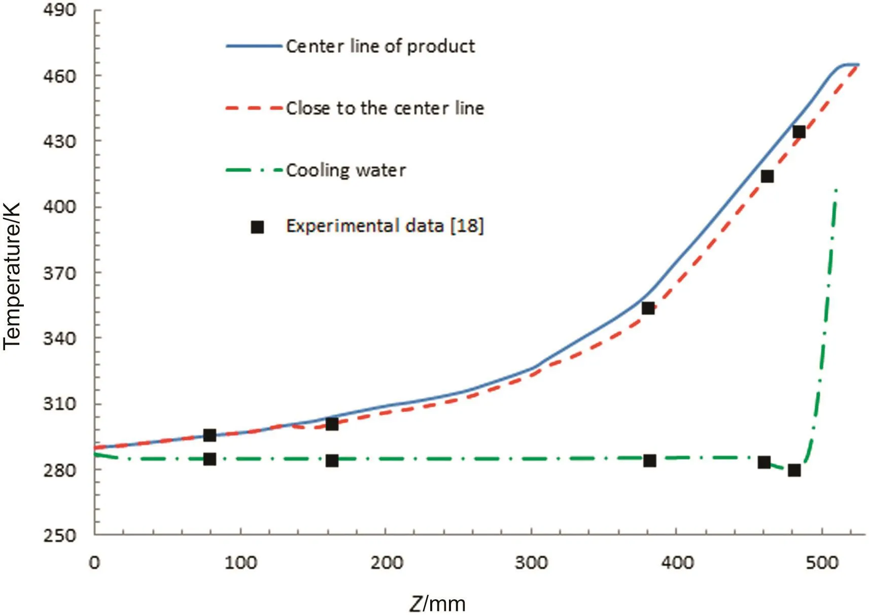
Fig.2.Simulated temperatures and experimental data for the product and the cooling water along the heat exchanger.
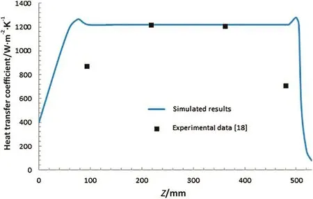
Fig.3.Distributions of heat transfer coefficients along the heat exchanger(simulated results and experimental data).
Fig.3.illustrates the distribution of heat transfer coefficients through the outer wall of the inner tube.The heat transfer coefficients remain almost constant between the inlet and outlet regions of the cooling water.At the cooling water inlet and outlet,the heat transfer coefficient is increased and the maximum values occurred in these regions.At the middle of the heat exchanger,the simulated results are in a high precision agreement with the experimental data.Although the basic trend is followed well near the inlet and outlet regions,there are some differences between simulated results and experimental data in these regions.These differences occur because in the experimental study some correlations are used to estimate the heat transfer coefficient that are not applicable exactly for the operating condition and they are only closest possible equations for the operating conditions[18].Thus,because of the mentioned problem the trend of the results are more important in the comparison of the simulated results and experimental data than the exact reported data;by considering the trend of the simulated results in Fig.3,the basic trend is followed with high precision.
In the second case, fluid flow and heat transfer is investigated through a channel filled with metallic porous media.Velocity distribution andNunumbers for the numerical results are validated with available trustful data reported by Xuet al.[32].The geometry for this case is shown in Fig.4.LandHare the length and half of the height of the channel,respectively.The parameters defined for this part of simulation are porosity=0.9,Re=1500,H=0.01 andL=0.1.
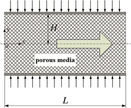
Fig.4.Geometry of the simulation for validation of the porous model(a channel filled with porous media).
Velocity distribution through the porous media for numerical results and analytical data reported by Xuet al.[32]are shown in Fig.5.The results show that the fluid flow through the porous model is in a high precision agreement with the analytical data[32].
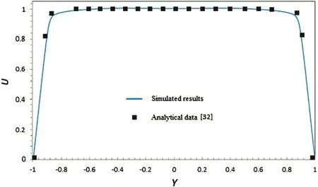
Fig.5.Velocity distribution through the channel filled with porous media(Y=y/H and U=u/u in).
To validate heat transfer in porous media model,Nunumbers are compared for the numerical results and analytical data reported by Xuet al.[32].Table 3 reports the calculatedNunumbers for different values ofX(X=x/H).The results show thatNunumbers are in a good agreement with analytical data and confirm precision of the porous model in this study.
(5)钻井参数、钻井液性能不合适。不适应地层的钻井液将大大制约钻井速度和影响井身质量,严重的将导致井下故障复杂化;钻井施工过程中缺乏详细的具有指导意义的钻井液性能参数和药品加量。

Table 3Nu number(numbers are rounded to the nearest number)
3.2.Using porous media for heat transfer enhancement
In the typical configuration of the heat exchanger,the product temperature descends 100 K when passes a 130 mm distance through the inner tube for 2 s,that means the product cooling rate is 50 K·s-1.As shown in Fig.6,by implementing the porous media in the heat exchanger,the product temperature is reduced by 140 K flowing the same distance through the inner tube at the same time.This means that the product cooling rate is 70 K·s-1in this case.Accordingly,the results reveal that using the porous media in the heat exchanger causes 40%increase in the cooling rate,which is a considerable change.The rate of cooling in the porous heat exchanger enhances for two main reasons:the characteristics of porous media and the effectiveness of our new proposed configuration for the porous media,which enhances the heat transfer in the heat exchanger.
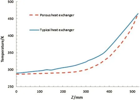
Fig.6.Temperature distributions of the product along the heat exchangers(typical heat exchanger and porous heat exchanger).
Fig.7 shows the temperature contours around the product inlet and cooling water outlet regions of typical and porous heat exchangers.The contours corroborate a considerable increase in the cooling rate of product in system with porous media and reveal that applying the porous media leads to higher cooling capacity.As illustrated in Fig.7,in porous heat exchanger,high temperature region of the product ends at 25 mm far from the inlet,while the corresponding distance is about 60 mm in typical heat exchanger.Surely,higher amount of the cooling rate leads to higher quality of the product.Using the porous media,on the other hand,enhances the heat exchanger effectiveness,which results in 35%decrease in its required length.
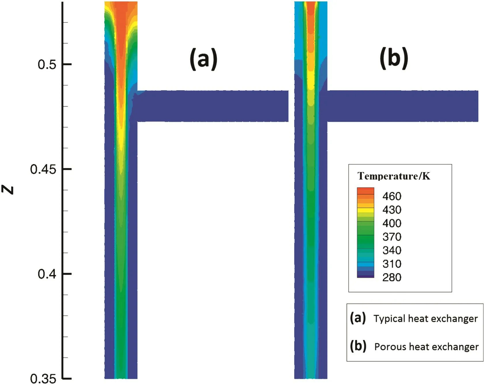
Fig.7.Contours of temperature around the product inlet and cooling water outlet regions(a.Typical heat exchanger;b.Porous heat exchanger).
The pressure drop in the heat exchanger should also be taken into consideration as a restriction of porous media utilization in heat exchangers.Fig.8 shows the average pressure distribution of cooling water along the typical and porous heat exchangers.The pressure drops of cooling water in the typical and porous heat exchangers are very close to each other with their maximum not more than 200 Pa for both stages,as shown in Fig.8.Therefore,using porous media is acceptable for this application with relatively low pressure drop.

Fig.8.Average pressure distribution of cooling water along the typical and porous heat exchangers.
3.3.Obtaining the optimum thickness of the porous media
Through examining six different thicknesses of the porous media,the most efficient thickness for maximum cooling rate is obtained.By increasing the thickness up to a particular value,reduction in heat transfer coefficient caused by decrement in the cooling water velocity(for a constant pressure loss in each side of the heat exchanger)surpasses the increment caused by the porous media.Consequently,taking an optimum thickness for the porous media will improve the operation of the system.As listed in Table 4,the effective length of the heat exchanger is increased as the thickness becomes more than 0.40 mm.Therefore,the value of 0.40 mm is taken as the optimum thickness.

Table 4The minimum required length of the heat exchanger with different porous medium thicknesses
3.4.Design of the porous heat exchanger
The objective of this section is to find the minimum required length of the heat exchanger for different product inlet temperatures and different product and cooling water mass flow rates.The minimum required length of the heat exchanger for different product inlet temperatures and different cooling water flow rates is obtained in Figs.9-11.The product flow rates,respectively,are 20 ml·min-1,30 ml·min-1and 40 ml·min-1in these graphs.As shown in Fig.9,the required lengths of the heat exchanger for higher flow rates of the cooling water are more similar compared with those for cooling water flow rate of 0.8 L·min-1.As the cooling water flow rate increases,the minimum required length of the heat exchanger decreases and the minimum length becomes a function of inlet temperature and product flow rate.Comparing the results presented in Figs.9-11 reveals that by increasing the product flow rate,the minimum required lengths obtained for different cooling water flow rates become closer to each other.Fig.11 shows that in high inlet temperatures of the product,the minimum required lengths are the same for product flow rate of 40 ml·min-1.Hence,for higher product flow rates and higher temperatures,the minimum required length of porous heat exchanger is only a function of product inlet temperature.
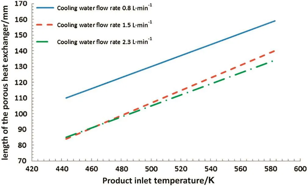
Fig.9.Minimum required length of the porous heat exchanger with the product flow rate of 20 ml·min-1.

Fig.10.Minimum required length of the porous heat exchanger with the product flow rate of 30 ml·min-1.
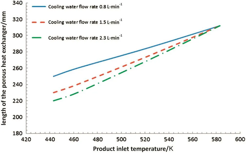
Fig.11.Minimum required length of the porous heat exchanger with the product flow rate of 40 mL·min-1.
Evidently,by minimizing the heat exchanger length,it is possible to enhance the quality of the productand reduce the consumed amount of materials for manufacturing of the heat exchanger in CHFS systems.
4.Conclusions
In this study,a new porous media configuration in a heat exchanger of a CHFS system is presented to improve the heat transfer and minimize the required length of the heat exchanger.At the first stage,a CFD modeling is carried out to simulate the fluid flow and heat transfer in the heat exchanger of the CHFS system.After validating the numerical results with available experimental data,porous media is added to the system.Then,six different thicknesses of the porous media are examined to obtain the optimum thickness.Finally,numerous simulation runs are conducted to obtain the minimum required length of the heat exchanger for various inlet conditions.
The obtained results can be summarized as follows:
·By applying the porous media in the heat exchanger,the product temperature reduces with the cooling rate of 70 K·s-1in 2 first seconds,which is approximately 40%more than the typical heat exchanger.Hence,using porous media in the heat exchanger has a significant influence on the cooling rate,which subsequently leads to higher quality of the product.
·The required length of the porous heat exchanger reduces by almost 35%compared with the typicalone,because the porous heat exchanger has a higher cooling capacity.
·The optimum thickness of the implemented porous media is 0.40 mm based on the minimum required length of the heat exchanger with porous media.
·The minimum required length of the porous heat exchanger is computed for different inlet temperatures and flow rates of the product as well as cooling water flow rates.These minimum required lengths give the opportunity to improve the quality of the product and reduce the cost of consumed materials for construction of a heat exchanger in CHFS systems.
Nomenclature
ACross sectional area,m2
CpSpecific heat transfer coefficient,kJ·kg-1·K-1
ETotal energy,kJ
GGeneration of turbulence kinetic energy
hSpecific enthalpy,kJ·kg-1
JiDiffusion flux,kg·m-2·s-1
kTurbulent Kinetic energy
Flow rate,kg·s-1
NuNusselt number
PPressure,Pa
PrtTurbulent Prandtl number
iHeat transfer rate,kW
Fluid enthalpy source term
TTemperature,K
UiHeat transfer coefficient,kW·m-2·K-1
uVelocity,m·s-1
β Volumetric thermal expansion coefficient,K-1
γ Porosity
ε Emissivity
λ Thermal conductivity,W·m-1·K-1
μ Dynamic viscosity,kg·m-1·s-1
ρ Density,kg·m-3
τ Shear stress,Pa
Subscripts
eff Effective
f Fluid phase
s Solid phase
t Turbulent
[1]J.A.Darr,M.Poliakoff,New directions in inorganic and metal-organic.Coordination chemistry in supercritical fluids,Chem.Rev.99(1999)495-541.
[2]T.Adschiri,K.Kanazawa,Rapid and continuous hydrothermal synthesis of boehmite particles in sub and supercritical water,J.Am.Ceram.Soc.75(1992)2615-2618.
[3]S.Moussiere,P.Joussot-Dubien,Modeling of heat transfer and hydrodynamic with two kinetics approaches during supercritical water oxidation process,J.Supercrit.Fluids43(2007)324-332.
[4]A.E.Scheidegger,The Physics of Flow Through Porous Media,Univ.Toronto Press,1974.
[5]M.Kaviany,Principles of Heat Transfer in Porous Media,Springer,1995.
[6]A.Aimable,H.Muhr,Continuous hydrothermal synthesis of inorganic nano powders in supercritical water:Towards a better control of the process,Powder Technol.190(2009)99-106.
[7]M.D.Bermejo,M.J.Cocero,Supercritical water oxidation:A technicalreview,AIChE.J.52(2006)3933-3951.
[8]E.Lester,P.Blood,Reaction engineering:The supercritical water hydrothermal synthesis of nano-particles,J.Supercrit.Fluids37(2006)209-214.
[9]M.Vesna,J.Christopher,K.Suela,Imaging the continuous hydrothermal flow synthesis of nano-particulate CeO2at different supercritical water temperatures using in situ angle-dispersive diffraction,J.Supercrit.Fluids87(2015)118-128.
[10]K.Brett,F.Veruscha,Critical process parameters and their interactions on the continuous hydrothermal synthesis of ironoxide nanoparticles,Chem.Eng.J.281(2015)312-321.
[11]E.Sherif,E.M.Hosam,Synthesis and surface modification of nanophosphorousbased flame retardant agent by continuous flow hydrothermal synthesis,Particuology22(2015)82-88.
[12]F.W.Dittus,L.M.K.Boelter,Heat transfer in automobile radiators of the tubular type,Univ.Calif.Publ.Eng.2(1930)443-461.
[13]E.A.Krasnoshchekov,B.S.Petukhov,V.S.Protopopov,An investigation of heat transfer to fluids flowing in pipes under supercritical conditions,Proceedings of the Second International Heat Transfer Conference,University of Colorado,Boulder,USA 1961,pp.569-578.
[14]J.D.Jackson,W.B.Hall,Forced convection heat transfer to fluids at supercritical pressure,Turbulent Forced Convection in Channels and Bundles,vol.2,Hemisphere Publishing Corporation,New York 1979,pp.563-611.
[15]M.J.Watts,C.T.Chou,Mixed convection heattransfer to supercritical pressure water,Proceedings of the 7th International Heat Transfer Conference,Munchen,Germany 1982,pp.495-500.
[16]N.Zhou,A.Krishnan,F.Vogel,A computational model for supercritical water oxidation of organic toxic wastes,Adv.Environ.Res.4(2000)79-95.
[17]J.Licht,M.Anderson,M.Corradini,Heat transfer to water at supercritical pressures in a circular and square annular flow geometry,Int.J.Heat Fluid Flow29(2008)156-166.
[18]Y.M.Cai,J.T.Christopher,Numerical modelling of hydrothermal fluid flow and heat transfer in a tubular heat exchanger under near critical conditions,J.Supercrit.Fluids57(2011)236-246.
[19]Y.M.Cai,J.Jing,Z.Yang,Z.Xue,Simulation for scale-up of a confined jet mixer for continuous hydrothermal flow synthesis of nanomaterials,J.Supercrit.Fluids58(2015)211-222.
[20]J.Gheorghe,The influence of the porous media permeability on the unsteady conjugate forced convection heat transfer from a porous sphere embedded in a porous medium,Int.J.Heat Mass Transf.77(2014)1124-1132.
[21]R.Fumei,Zh.Wenhuan,Sh.Baochang,Numerical study of heat transfer enhancement in a pipe filled with porous media by axisymmetric TLB model based on GPU,Int.J.Heat Mass Transf.70(2014)1040-1049.
[22]J.Wajs,D.Mikielewicz,Influence of metallic porous microlayer on pressure drop and heat transfer of stainless steel plate heat exchanger,Appl.Therm.Eng.93(2015)1337-1346.
[23]G.C.Bourantas,E.D.Skouras,V.C.Loukopoulos,Heat transfer and natural convection of nano fluids in porous media,Eur.J.Mech.B Fluids43(2014)45-56.
[24]W.Lin,B.Sundén,J.Yuan,A performance analysis of porous graphite foam heat exchangers in vehicles,Appl.Therm.Eng.50(2013)1201-1210.
[25]W.Wang,J.Guo,S.Zhang,J.Yang,X.Ding,X.Zhan,Numerical study on hydrodynamic characteristics of plate- fin heat exchanger using porous media approach,Comput.Chem.Eng.61(2014)30-37.
[26]D.C.Wilcox,Turbulent Modeling for CFD,Second ed.DCW Industries,California,1994.
[27]W.P.Jones,B.E.Launder,The prediction of laminarization with a two-equation model of turbulence,Int.J.Heat Mass Transf.15(1972)301-314.
[28]C.Somerton,P.Wood,Effect of walls in modeling flow through porous media,J.Hydraul.Eng.114(1988)1431-1448.
[29]D.A.Nield,A.Bejan,Convection in Porous Media,Third edition Springer,2006.
[30]C.Wang,Zh.Guo,D.Zhang,S.Qiu,W.Tian,Y.Wu,G.Su,Transient behavior of the sodium-potassium alloy heat pipe in passive residual heat removal system of molten salt reactor,Prog.Clear Energy68(2013)142-152.
[31]http://www.ansys.com/Products/Simulation+Technology/Fluid+Dynamics/Fluid+Dynamics+Products/ANSYS+Fluent.
[32]H.Xu,L.Gong,S.Huang,M.Xu,Flow and heat transfer characteristics of nano fluid flowing through porous media,Int.J.Heat Mass Transf.83(2014)399-407.
 Chinese Journal of Chemical Engineering2017年10期
- Chinese Journal of Chemical Engineering的其它文章
- Effect of carboxymethyl cellulose on dissolution kinetics of carboxymethyl cellulose-sodium carbonate two-component tablet
- Crystallization of calcium silicate at elevated temperatures in highly alkaline system of Na2O-CaO-SiO2-H2O☆
- Aluminum impregnated silica catalyst for Friedel-Crafts reaction:Influence of ordering mesostructure☆
- Microencapsulation of stearic acid with polymethylmethacrylate using iron(III)chloride as photo-initiator for thermal energy storage☆
- Novel efficient procedure for biodiesel synthesis from waste oils with high acid value using 1-sulfobutyl-3-methylimidazolium hydrosulfate ionic liquid as the catalyst☆
- Toluene degradation by a water/silicone oil mixture for the design of two phase partitioning bioreactors
