A robust online path planning approach in cluttered environments for micro rotorcraft drones
Shupeng LAI,Kangli WANG,Hailong QIN,Jin Q.CUI,Ben M.CHEN
1.NUS Graduate School for Integrative Sciences&Engineering,National University of Singapore,Singapore 117456;
2.Department of Electrical&Computer Engineering,National University of Singapore,Singapore 117583;
3.Temasek Laboratories,National University of Singapore,Singapore 117411 Received 12 January 2016;revised 23 January 2016;accepted 23 January 2016
A robust online path planning approach in cluttered environments for micro rotorcraft drones
Shupeng LAI1†,Kangli WANG2,Hailong QIN3,Jin Q.CUI3,Ben M.CHEN2
1.NUS Graduate School for Integrative Sciences&Engineering,National University of Singapore,Singapore 117456;
2.Department of Electrical&Computer Engineering,National University of Singapore,Singapore 117583;
3.Temasek Laboratories,National University of Singapore,Singapore 117411 Received 12 January 2016;revised 23 January 2016;accepted 23 January 2016
We present in this paper a robust online path planning method,which allows a micro rotorcraft drone to fly safely in GPS-denied and obstacle-strewn environments with limited onboard computational power.The approach is based on an efficiently managed grid map and a closed-form solution to the two point boundary value problem(TPBVP).The grid map assists trajectory evaluation whereas the solution to the TPBVP generates smooth trajectories.Finally,a top-level trajectory switching algorithm is utilized to minimize the computational cost.Advantages of the proposed approach include its conservation of computational resource,robustness of trajectory generation and agility of reaction to unknown environment.The result has been realized on actual drones platforms and successfully demonstrated in real flight tests.The video of flight tests can be found at:http://uav.ece.nus.edu.sg/robust-online-path-planning-Lai2015.html.
Unmanned aerial vehicles,mapping,path planning,trajectory generation
1 Introduction
Theabilitytonavigatethroughclutteredenvironments is crucial to many higher level robotic applications such as flocking,exploration and target tracking.A key to achieve this capability is a sophisticated path planning system,which is to produce trajectories that lead the vehicle traveling safely through obstacles.The system needs to observe the environment,make decisions accordingly and generate necessary commands for lower level controllers.Based on these tasks,it usually consists of modules that handle perception and planning separately.A perception module is responsible for environment observation that includes obtaining the states of the vehicle(i.e.,localization)and calculating the location of obstacles(i.e.,mapping).A planning moduleinvolves finding trajectories that satisfy the vehicle dynamics and environmental constraints.The lower level controllers then take these trajectories as references to drive the vehicle accordingly.Such a scheme is widely adopted in the area of robotics[1-3].The detailed approaches for the perception and planning phases vary largely due to the difference on vehicle types,sensors,targeted environments and applications.In this paper,wefocusondevelopingapathplanningsystemforrotorcraft drones in GPS-denied and cluttered environments.The planning and perception modules are studied to elaborate their connections that provide guidelines on tailoring their algorithms to improve efficiency.
Many of the algorithms adopted by micro aerial vehicles(MAVs)or drones are originated from the robotic research community.Unfortunately,unlike the ground robots or vehicles,MAVs come with very limited payload and computational power.Those smaller drones,such as the quadrotor adopted in our research as depicted in Fig.1,normally carry less than 500 grams and have low-speed onboard computers.For such drones,it is hard to implement the commonly used methods onboard.It is necessary to develop algorithms that consume less memory and computational resources,which is the subject of studies in this work.
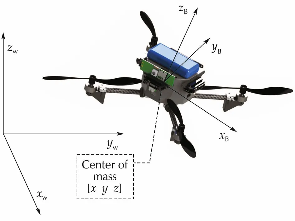
Fig.1 Frames used:the left corner shows the global frame while the body frame is shown along with the vehicle.
To save memory space,a rolling map structure is adopted to handle an infinitely large environment with limited memory space.It also comes with algorithms for evaluating trajectories on the map using voxel based methods.On the other hand,it is noticed that the online generation of smooth and collision-free trajectories is usually computationally intensive and probably unreliableinrealtimeifnumericalsolutionsarerequired.We propose an algorithm to split the trajectory generation process into solving a series of TPBVPs.An closed-form solution to the TPBVP is developed to further improve the overall efficiency.
The rest of the paper is organized as follows:In Section 2,we introduce the system design procedure,which details the connection of the perception,planning and action phases in our proposed system.Section 3 presents a discretized structure of expressing the surrounding environment for the planning algorithm,whereas Section 4 describes the path planning and trajectory generation algorithms,which are capable of generating smooth trajectories to lead the UAV to fly through an obstacle dense environment.The experimental results and analysis are given in Section 5.Finally,we draw some concluding remarks in Section 6.
2 System design
The power source that lifts a quadrotor drone is its four propellers.By controlling the rotating speed of each propeller,it is able to manipulate the attitude and position of the drone.In our studies,we adopt both the coordinate systems of the world frameWand the vehicle body frameB,which are shown in Fig.1.TheZ-X-YEuler angles are used to define the roll(φ),pitch(θ)and yaw(ψ)angles of the rotating body frame.The model of the drone is adopted from[4]and it is proven to be differentially flat.That is,with the chosen flat outputs of the system:

all the system’s states could be expressed as these outputs and their derivatives.Here,the[x y z]is the position of the mass center in coordinateWand ψis the yaw angle of the vehicle.Due to the differential flatness,trajectories of the system can be studied in the reduced space of flat outputs rather than the full state space.This result helps to decrease the dimension of the planning problem and enable the online trajectory generation.
To track trajectories of flat outputs,a cascaded control structure is adopted from[5].The inner loop is in charge of the attitudes control whereas the outer loop handlesthepositiontracking.Thisdesignisbasedonthe fact that the inner loop bandwidth of the drone is much higherthanitsouterloop.Thefunctionalstructureofthe system is shown in Fig.2.The detail of position and attitude controllers can be found in[6].The localization of the vehicle can be done using either velocity estimation methods such as the optical flow or complex ones like simultaneous localization and mapping(SLAM)[7].The path planner considers current target and surrounding environment to generate jerk limited trajectories in the space of flat output as in(1).For a rotorcraft,its trajectory consists of position,velocity,acceleration and jerk information.Thetargetforthepathplanneriseitherprovided by a human commander or by other higher level task manager.
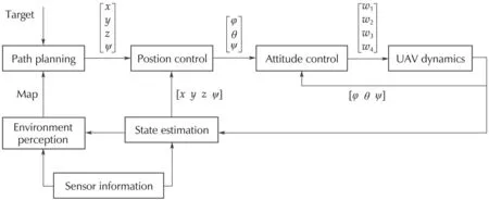
Fig.2 System structure of 7 different functional blocks.The attitude controller tracks the angle reference by controlling the rotating speed of propellers[w1w2w3w4].The position controller tracks the trajectory provided by the path planner.
3 Perception of the environment
We discuss in this section the localization and mapping methods that transform the environmental information into efficient data structure to serve the path planning algorithm.The two basic tasks of analyzing the environment are to localize the vehicle itself and build a map of the world.The SLAM technique is commonly adopted to localize the vehicle in GPS-denied environment.The implementation of SLAM algorithms depends on the type of perception sensors used,such as RGB-D sensors and 2D laser range finders.The use of RGBD sensors was first presented in[8]and more details are covered in[9].The main idea is to match sparse visual features associate with dense depth information to obtain an initial estimate of the relative frame transformation,which is then refined by using iterative closet point(ICP).The 3D mapping provided by RGB-D sensors requires complicated data structure to represent the map and perform query search in the map,which is too time-consuming to be implemented on mobile computers onboard a MAV.On the other hand,2D laser range finders provide accurate distance measurements in a 2D plane,making them ideal sensors for environments such as indoor offices or urban canyons.SLAM using 2D laser range finders have been extensively covered in the literature.Open source packages like GMapping[10]and Hector-SLAM[11]are available for indoor environments.Algorithms describing SLAM in forest environment are covered in[12].In this paper,we use Hector-SLAM for localization in indoor offices.
Followingthelocalization,anenvironmentalmapwith necessary data structures and analyzing functions is required for planning algorithms.Among all the map analyzing functions,the most important ones are i)to efficiently determine the distance of a given point on the maptoitsclosestobstacle,andii)toevaluateagiventrajectory so that its property can be assigned with a score.The former is used to check the minimum distance between the vehicle and obstacles,whereas the latter is used for collision checking and closeness assessment.
Since our task is not to map the whole flying area,a grid based rolling map is chosen to store the world information,which is essentially a fix-size grid structure that allows vehicles to move out of its boundary and re-enter into the map.Transforming from a given real world position to the cell number of the rolling grid map is given in Algorithm 1 below:

Here the “Origin′′is the real world position on the grid map’s(0,0,0).The “GridSize′′is the width of the grid and the positive_modulo function performs the rolling action.Each gridgis represented by three in-teger numbersg.x,g.y,g.z,respectively,corresponding to its grid number along each axis.The size of the rolling map must be larger than the vehicle’s sensor range to keep the continuity of information.For every obstacle captured by the sensors,its position is projected onto the map by first performing a coordinate transformation from the body frameBto the world frameWand then mapped onto the grid map.The true position of the vehicle is acquired through the state estimation module,which is obtained through the Hector-SLAM algorithm in our case.
Asimplewaytoaccesstheshortestdistanceofagiven point on the map to obstacles is to scan through grids around each obstacle and assign distance values to each grid within the radius of interest.Other methods based on the Euclidean distance transformation(EDT)algorithms(see,for example,[13])could also be used.To our experience,if the sensor returns very limited informationoftheenvironment,theabovementionedsimple method would perform better than the EDT based ones.However,if the sensor,such as an RGB-D camera,is capable of providing rich information,the EDT methods would give a better result.
Fig.3 shows a typical grid map with updated obstacle and distance information.
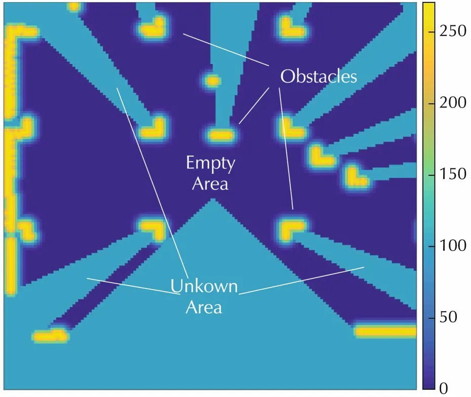
Fig.3 A cost map generated by laser scanner.
For a given gridgon the map,its distance to the closest obstacle is denoted as EDT(g).In our implementation,instead of just taking the distance information,we have also assigned a cost Cost(g)for each grid according to their EDT value.The cost value is reciprocal to the distance of a grid to an obstacle.The area blocked by obstacles are marked as unknown and given a medium cost value.This is used for path planning,in which we run an A*algorithm based on this cost map.
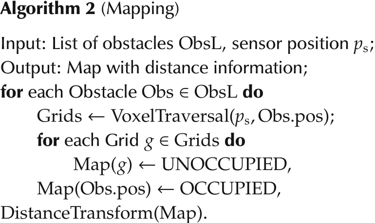
Another problem of mapping are the moving obstacles.If we only project the sensed obstacles and accumulate them in the map,a moving object would leave its trace as a wall of obstacles in the grid map,which would render the map useless.A common way of solving such a problem is to reduce the cost value of each grid in every scan frame before adding the newly sensed information.That is,for each grid on the map,do Cost(g):=Cost(g)·kwith 0<k< 1 for every scan.However,this leads to losing of history information when an object is out of the sensor’s range for a certain period of time.To tackle this problem,it is noticed for most of the range sensors,such as sonars,laser scanners and depth cameras,there is a line-onsight relationship between the obstacle and the sensor.Moreover,the space in between are obstacle free.This property is utilized along with a voxel traversal method in Algorithm 4 to clean the space between the sensor and the obstacle.The procedure of mapping in our implementation is given in Algorithm 2.
On the other hand,to perform the collision checking and trajectory assessment,a foot-print of the vehicle following a given trajectory on the map is needed.In our case,this is made easy by the fact that the vehicle has a similar width,length and height,which could be treated as a sphere in 3D or a circle in 2D space with distancerv.For a given trajectoryS,the minimum distance to obstacles when vehicle travel through it is given by

whereGis a set of grids covered by the trace of the trajectoryS.An approximation method is then used to extract the trace of a given trajectory and project it onto the grid map.Since the trajectory could be in the form of polynomials,splines or results of forward simulation,a general solution to project the trajectory onto the grid map and retrieve a list of grids is rather difficult and time consuming.For our implementation,all trajectories are approximated by a series of line segments,which are acquired by sampling the original trajectory at discrete time instances.Afterwards,each of these segments is examined by a fast voxel traversal algorithm[14].
LetPlistbe a list of points in the configuration space that is generated by sampling the trajectorySat discrete timet0,t1,t2,....The algorithm of retrieving a list of grids,through which the trajectory passes,is given in Algorithm 3:
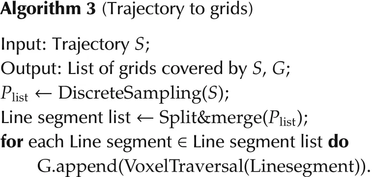
Each line segment is represented by its starting point,pstart,and the end point,pend,respectively.The voxel traversal algorithm in 2D is shown in Algorithm 4.
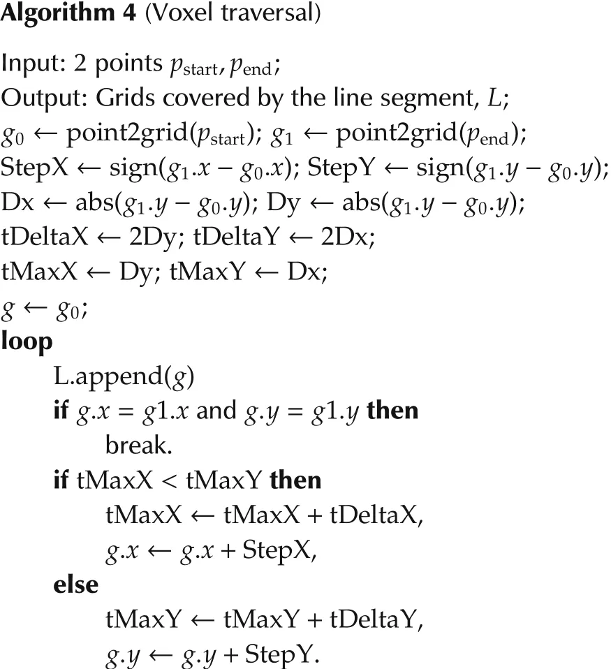
Here the point2grid function is given in Algorithm 1.The approach is different from the commonly used Bresenham’s algorithm,which does not return all the grids covered by the line segment,providing weaker checking foreachtrajectory.ThedifferencebetweenBresenham’s algorithm and ours is highlighted in Fig.4.
Our approach actually passes through all the grids whereas the Bresenham’s algorithm ignores some along the way.It would cause problems if the ignored grid happens to be an obstacle.
Lastly,by checking each of the gridg∈Gin Algorithm 3 for its EDT(g),we could determine the safeness of the trajectory generated.With all these basic tools,fast planning and checking of a trajectory is made possible.

Fig.4 Comparison between Bresenham’s algorithm,the adopted algorithm provides more safety by returning all grids covered by the line segment.
4 Path planning algorithm
Path planning,like many other engineering problems,can be cast as an optimization problem.For a linear time-invariant discrete-time system:

whereA,BandCare constant matrices with appropriate dimensions,xk,ukandykare respectively the state,input and output variables of the system at timek.We denoteU=[u0u1u2···uN-1].The path planning problem can be described as
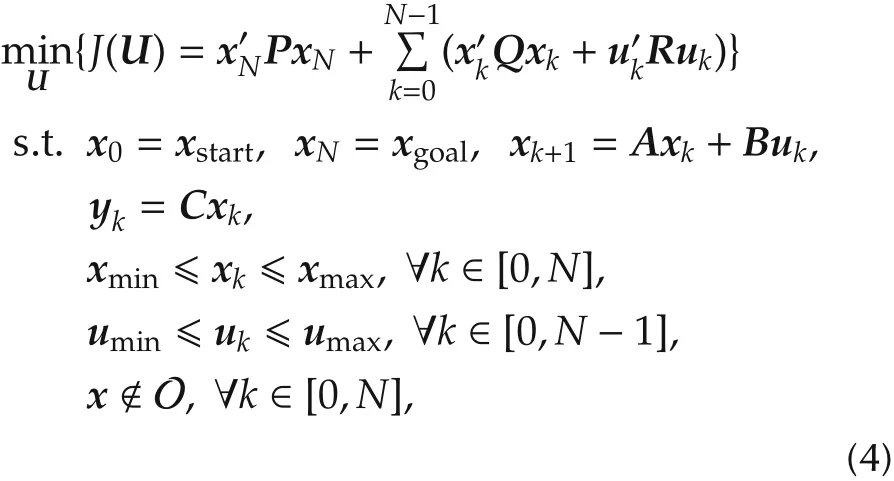
whereP,QandRare positive definite,xstartandxgoalare the initial and end states of the vehicle,is a subset of the state space that is not allowed to enter which includes all the real obstacles and human-set boundary.
Unfortunately,thereisnoexplicitsolutiontothisoptimization problem.Though numerical methods exist[4],its performance is usually limited by the size and complexity of the optimization space.Furthermore,numerical methods suffer from the possibility of divergence and providing a control sequence that could potentially damage the vehicle.Therefore,extra checking and validation of the trajectory are required and further slow down the computation process.In this work,we adopt a two-step solution to tackle the problem.Firstly,we largely ignore the vehicle dynamics and focus on the topological information of the environment to search for a safe pass way on the map.We then design smooth trajectories following these pass ways with the vehicle dynamics considered.
Since a rotorcraft is capable of performing hovering and moving to all directions,we simplify it as a checker moving on the grid map.For a 2D map case,the checker couldmovetowards8differentdirections:left,right,up,down,top left,bottom left,top right and bottom right.For the left,right,up and down movement,the traveled distance is 1 unit and for the top left,bottom left,top righ and bottom right movement,the traveled distance isunit.Here we choose the classical A*algorithm which is also frequently considered as a graph search method to generate a safe pass way.Inputs to the A*algorithm are the start and goal point in the configuration space.Results of the algorithm is a sequence of map grids.A typical A*pass way is shown in Fig.5.
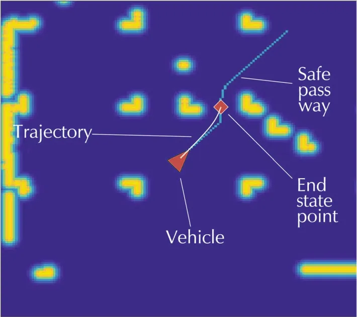
Fig.5 The safe pass way is shown as green line segments.The endstatepointispickedaroundthelastpointstayline-on-sight to the start point.
However,due to the overly simplified dynamics,the pass way itself cannot be directly used as an outer loop reference for the actual vehicle.To generate a feasible trajectory,the vehicle dynamics must be considered.
As stated in Section 2,the trajectories of a rotorcraft are designed in the flat-output space where it consists of[x y zψ]and their derivatives(a.k.a.velocities,accelerations,jerk,snap,etc.).The most widely adopted method is numerical optimization based[4,15].This approach handles multiple “key-frame”problem and generate minimum snap trajectory that takes into account of the full dynamics of the drone.Here,a keyframe means one more extra constraints in the form ofxk=xchosenfor the optimization problem in(4).In general,this method gives a well-formed,smooth trajectory that stays close to the safe pass way.Unfortunately,direct optimization methods usually result in a huge optimization space[16].It is a common practice to utilize spline approximation to reduce the size of the problem[15].
The major drawback of this approach is the numerical instability which requires extra effort to take care and increase the overall complexity of the algorithm.In this paper,we adopt a rather different bang-bang control based trajectory generation idea.The method could solve for TPBVP with differential constraints and we use it to generate jerk-limited trajectories.Unlike the minimum snap trajectory,jerk limited trajectory ignores some of the vehicle dynamics but is proven to be good enough for normal flight.According to[17],with a properly designed attitude feedback control law,the tracking error caused by the ignored dynamics of the jerk limited trajectory is insignificant compared to disturbances and sensor noises.Another important reason is the jerk limited trajectory could be solved analytically without worrying the performance of the numerical optimization.Nonetheless,according to[4],the angular speedp,q,rof the vehicle can be expressed as

whereais the acceleration of the center of mass,Tris the net body force from the propellers andxB,yB,zB,zwarethebasevectorsofthebodyframeas showninFig.1.
From(5),it is clear that the angular velocity of the vehicle is bounded by choosing a jerk limited trajectory.Thus,a smooth flight experience can also be achieved by limiting the jerk.
Since this is a TPBVP solver,only two-key-frames problem can be handled.Naturally,we set these two key-frames to be the initial and end states of the trajectory.The initial state is chosen as the current state of the vehicle to avoid reference discontinuity during switching of trajectories.The end state is required to be at hover condition due to safety consideration.By satisfying conditions given in(6)below,even the algorithm fails due to unexpected reason,the vehicle will end up with a safe hover.

As in Fig.5,the end state point[xendyendzend]is chosen to be a point around the last line-on-sight point on the safe pass way to the vehicle.This choice is made to force the vehicle to stay close to the safe pass way.One could imagine a trivial case where the vehicle picks such an end state point,flies towards it in straight line and hover,then picks another end state point and repeat the process.In such a case,the vehicle will stay close to the safe pass way while avoiding all static obstacles.
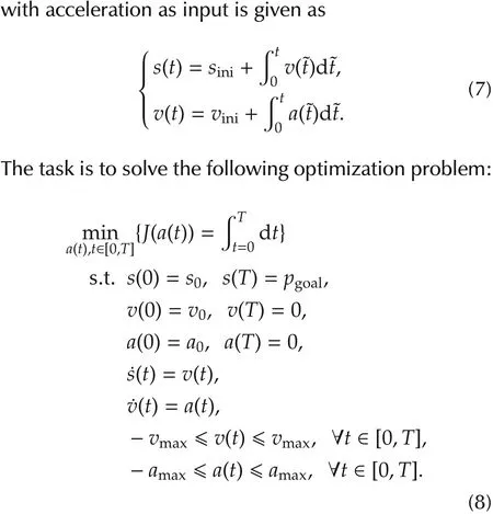
After the boundary values are properly set,the TPBVP is solved by an algorithm proposed in[18],which is depicted below with modifications to suit our task.We introduce the algorithm with an acceleration limited trajectory solver where it could be extended to solve jerk limited problems as in[19].A second order integrator
Due to the minimum time requirement,it is proven that theaccelerationcanonlybechosenbetweenamax,-amaxand0[20].Withsuchachoice,thevelocityprofilewould form a trapezoidal shape consists of three phases as given in Fig.6.
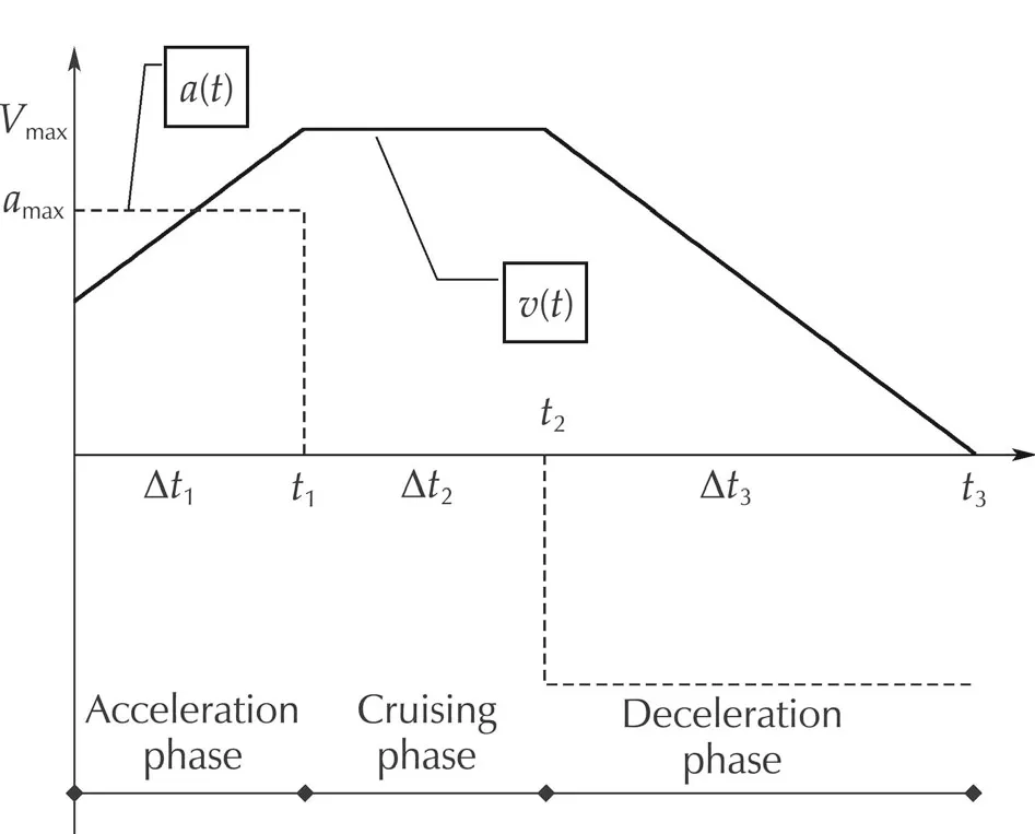
Fig.6 A trapezoidal velocity profile,the corresponding acceleration is discontinuous but bounded.The trapezoidal profile could be represented as acceleration phase,cruising phase and deceleration phase.

whered∈{-1,1}is the cruising direction.To solve for the trajectory,we need to solve fort1,t2andt3,respectively.We first determine the direction of the cruising phase as

wherepstopdenotes the point reached if the vehicle is immediately slowed down to zero velocity.By checking the relative position ofpstopto the final targetpgoal,we could determine the directiondat which the vehicle should travel further to reach its goal.
The algorithm to determine the parameters of a acceleration-limited,minimum-time trajectory is given in Algorithm 5.

Notethat,whenΔt2< 0,itrequiresthecruisingphase to have a negative time endurance,the cruising phase does not exist.For a second order system,its velocity trajectory ends up with a wedge-shaped profile where thevmaxis never going to be achieved.We would thus need to calculate the achievable maximum velocity and the corresponding time for acceleration and deceleration phases.
For multi-dimensional cases,we notice that the end state is at the full-stop,the trajectory will eventually reach the final state for each dimension.However,since the time consumption for each dimension is unequal,the trajectory might be counterintuitive as illustrated in Fig.7.One possible solution is to find the dimension that takes the longest timeTlongto reach the target and we explicitly require other dimensions to slow down and takeTlongtime to finish[21].However,this involves much more calculation compared to the onedimensional case,especially to solve jerk-limited problem.We employ a coordinate rotating procedure to solve such a problem by creating a new frame based on the safe pass way’s location and orientation as shown in Fig.7.
In the new frame,the trajectory for each dimension is calculated separately and transformed back to the original coordinate.It results a trajectory that will converge to the rotated axisx′in minimum time,which is preferred in our case since now the axisx′corresponds to the safe pass way.
To extend the solution to the jerk limited case as in[19],the same approach that solves the acceleration limited problem is adopted.Firstly,it determines the sign of cruse direction.It then checks if the maximum cruse velocity is reachable.If it can be achieved,the curse time is then calculated.Otherwise,if it cannot be achieved(i.e.,the cruse time is negative),the reachable maximum velocity needs to be calculated.For the limited jerk trajectory,the acceleration profile is either trapezoidal(T)or wedged(W)for each acceleration or deceleration phase.It is shown in[19]that the overall acceleration profile is either T-T,T-W,W-T or W-W shaped and for each case a closed-form solution exists.Therefore,to determine the reachable cruse velocity,each of the T-T,T-W,W-T and W-W cases are tried until one of them gives a possible solution where time durations for acceleration,curse and deceleration phases are all nonnegative.The detailed expressions of these closed-form solution can be found in[17-19].
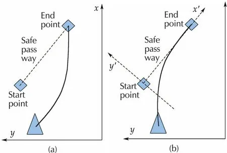
Fig.7 The left figure represent the result of performing unsynchronized trajectory generation in global frame.The result is counterintuitive and away from the safe pass way.The right figure shows the result of un-synchronized trajectory generation in a new frame by aligning its x axis to the safe pass way.The result is intuitive and close to the safe pass way.
Given a closed-form solution to the TPBVP bounded with the end state condition in(6),the vehicle will enter hover state each time when it finishes a trajectory.This is,however,not desirable for fast and efficient flight.A common solution is to combine the TPBVP solver with a receding horizon control(RHC)strategy.This is also referred to as the model predictive equilibrium point control(MPEPC)[22].The idea is to follow each newly generated trajectory for only a certain amount of time,which is usually shorter than the full time length of the trajectory.Then switch to a new trajectory based on a newlypickedendstatepointandthecurrenttrackedreference as initial state.As such,the vehicle would travel continuously without pausing.However,since a new plan and trajectory are generated every short amount of time,the computational power consumed would increase.Moreover,when using the proposed trajectory generator,discontinuity of jerk is likely to appear becauseofswitching.Thisisduetothetimeoptimalnature of the bang-bang strategy,which always uses the maximum control effort.According to(5),a discontinuity on jerk causes sudden change on the angular ratepandq.Though the effect is minor whenpandqare bounded,it could decrease the tracking control performance during aggressive maneuver where the angular speed is large.
To improve the situation,it is needed to reduce the amount of trajectory switching.The solution is to examine if the current trajectory is about to enter the deceleration phase before generating a new trajectory and switching to it.It carries the idea to remain on a trajectory as long as possible and only switches when unnecessary pausing is about to happen.However,due to dynamic obstacle or sudden environment change,the current trajectory could become invalid.In such a case,we need to solve for a new trajectory which leads the vehicle safely away from collision and switch to the new trajectory immediately.If we denote the current trajectory as CT,a possible trajectory as PT and the emergency trajectory as ET,the overall algorithm for trajectory checking and trajectory switching is shown in Algorithm 6.
InAlgorithm6,thelastTargetisusedtorecordtheend state point from the previous cycle.It is initialized as the current position of the vehicle.The localTargetSearch()function returns the last line-on-sight point on the safe pass way to the vehicle,and the BVPS()function is the boundary value problem solver introduced above.To check the validity of a trajectory,not only the trajectory itself is considered but also a group of trajectories that are distributed based on the current tracking error.These trajectories predict the future evolution of the tracking error in a linear term.

If the CT is still valid and it is entering the deceleration phase,the safe pass way is searched using the grid map with its starting point as the lastTarget.Then,we randomlysamplemultiplepointsaroundthelastline-onsight point on the safe pass way and generate trajectory for each of them.Finally,the trajectory that is farthest from obstacles is chosen.The process is illustrated by Fig.8.

Fig.8(a)Step 1:Safe pass way is generated,the first end point is picked around the first sharp turn.(b)Step 2:vehicle starts to pick new end point when it is about to enter the deceleration phase of the first trajectory.(c)Step 3:by repeating the process in Step 2,vehicle could reach its target.
Ontheotherhand,iftheCTisnotvalid,anemergency avoiding trajectory is generated and used immediately as shown in Algorithm 7.
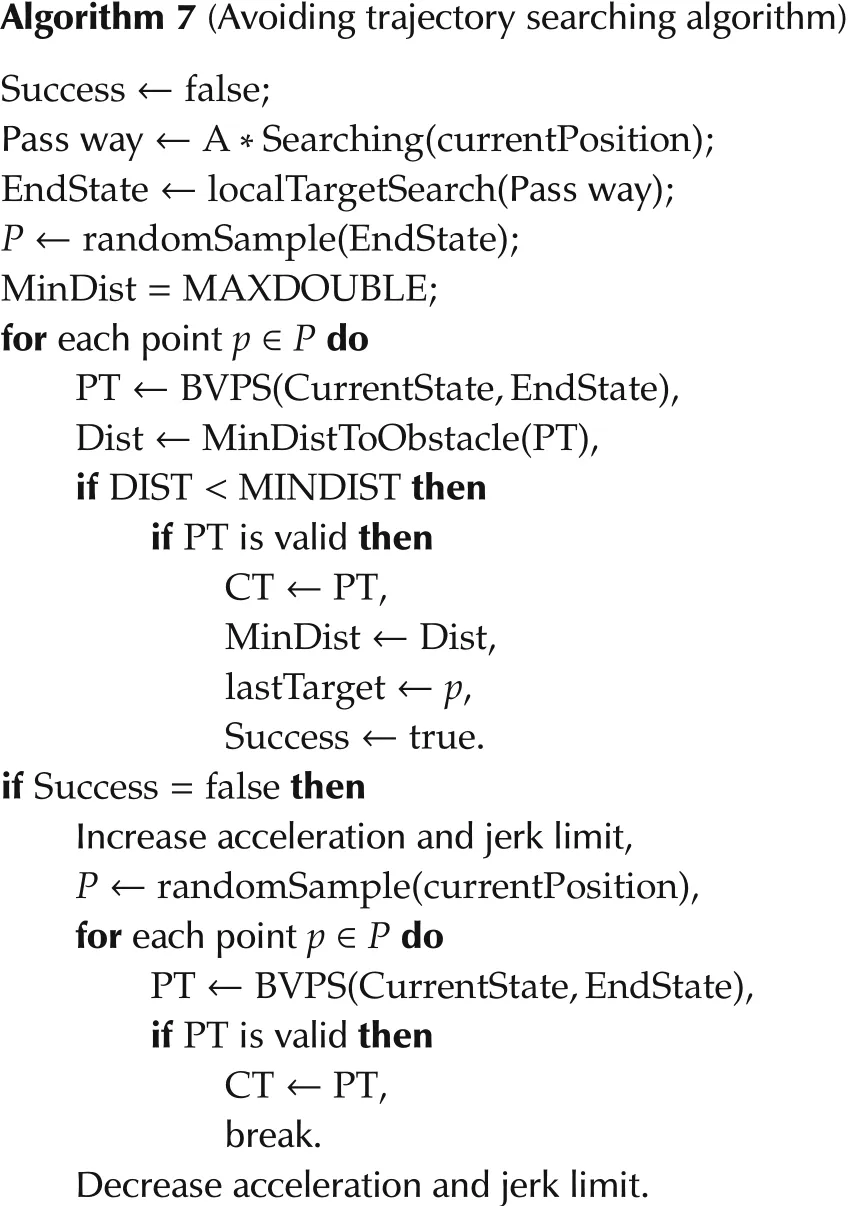
During avoiding trajectory searching,we first focus on trajectories that lead closer to the target and also away from collision.If these trajectories are not applicable,the vehicle is possibly in a dangerous situation.The limit on jerk and acceleration will be increased to allow the vehicle to perform more aggressive maneuver to avoid the possible collision.
A comparison between our algorithm and the traditional RHC method is shown in Fig.9.For each algorithm,the vehicle is required to pass through the same environmentwiththesamestartingpointandgoalpoint.
The RHC method is executed at 5Hz.Due to the lack of energy minimization term in the TPBVP solver and the frequent shifting of target,the trajectory consists of many unnecessary acceleration and deceleration.On the other hand,our proposed method generates smoother trajectory with less wobbling.Furthermore,our method reaches the target 5 seconds faster than the RHC based algorithm.We note that the RHC based method can be improved by using more complicated trajectory generation algorithm that provide minimum jerk or minimum snap trajectory.However,these algorithms usually requires numerical optimization and more complex solution is also resulted.
The advantage of our approach is obvious.It allows us to use TPBVP solver to generate nonstop and smooth trajectories for the vehicle.Unlike other numerical optimization based methods,which formulate complex or non-convex problems,the analytical closed-form solutions for the TPBVP are more reliable.
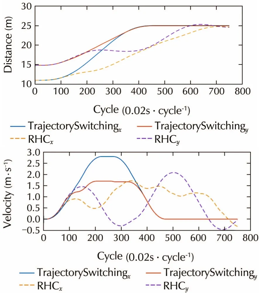
Fig.9 The RHC based strategy compared to the proposed trajectory switching algorithm.The proposed algorithm generates smoother,faster trajectory.
5 Experimental results
The platform employed to test our path planning scheme is a BlackLion-068(BL-068)shown in Fig.10,which is an AeroLion Technologies product.BL-068 is an octocopter with an X8 configuration using 8 motors that are mounted on an “X”shaped frame with four sets of clockwise(CW)and counter clockwise(CCW)propellers.
The overall dimension is 26cm in height and 68cm from tip-to-tip including the propeller protection,with a maximum take-off weight of 4kg.The bare platform weighs about 1kg including motors,propellers and protections.The compact size,light weight and large payload capability makes the platform an ideal testbed for confined environment navigation.
BL-068 comes with an inner loop flight controller,a TeraRanger One distance sensor and an Intel Next Unit of Computing(NUC)computer.The TeraRanger One distance sensor has a maximum measurement range of 14m with accuracy of±2cm.A Hokuyo 30m laser range finder is then installed on the platform for SLAM and path planning.
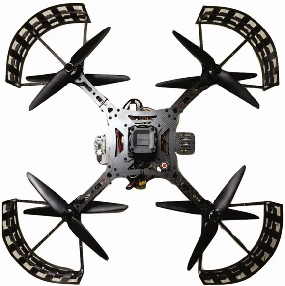
Fig.10 The X8 configuration octocopter BL-068 from ALT.
The experiment is done in an indoor clustered environment as depicted in Fig.11.
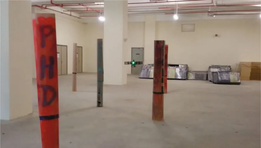
Fig.11 Experiment environment consists of pillars and other obstacles.
In such an environment,the vehicle is able to navigate through it safely with speed around 1.5m/s.The trace of trajectory flying through obstacles is shown in Fig.12.

Fig.12 Obstacle avoidance trajectory using a well tuned controller.
The corresponding velocity profile of the trajectory and tracking performance are given in Fig.13.

Fig.13 Tracking control performance of the well tuned controller.
The top speed combining both axis is at 1.4m/s.With a well designed control structure,the position tracking error is limited within 0.25m.
As mentioned in Section 4,in the trajectory validating process,we have also taken into consideration of tracking errors to reject trajectories that are risky due to bad control performance.To simulate such a situation,the control gains of the vehicle are tuned off from its optimal point so that the maximum position tracking error can reach 0.6m which is more than twice compared to that in the previous case.The vehicle is still able to navigate through the cluttered environment and the resulting trace of trajectory is shown in Fig.14.
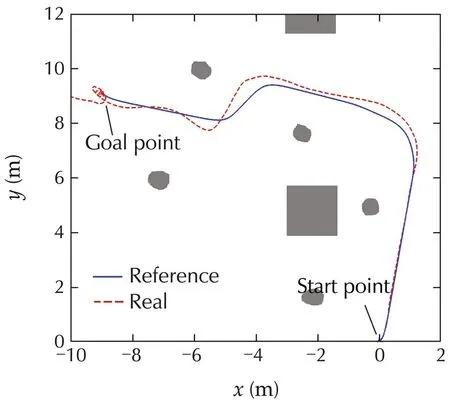
Fig.14 Avoidance trajectory with high tracking error.
Furthermore,to demonstrate the reliability of our approach,a simulated vehicle is made to fly successfully through a 500m×500m forest as shown in Fig.15.Due to the rolling map we adopted,the whole mapping and planning modules consumes less than 128MB of memory.All these results have proven the proposed path planning approach is robust and reliable.More importantly,it is suitable for real-time implementation.
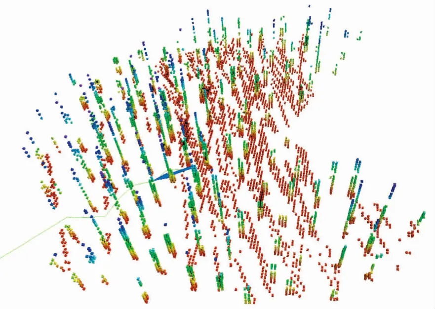
Fig.15 UAV flying through a simulated forest.
6 Conclusions
We have studied in this paper a computationally efficient and stable method to guide the rotorcraft drones to fly through cluttered and GPS-denied environments.The importance of map building and its connection to the following planning stage is made clear.The map and its associated data structure needs to be compatible with the planning algorithm and provide efficient functions to evaluate given trajectories.A two-step approach is adopted to generate sub-optimal solutions to the general planning problem.A closed-form TPBVP solvers are used for trajectory generation.A top-level trajectory switching algorithm is proposed to further reduce the computational cost and increase tracking performance.The key advantage of our approach is the adoption of a closed-form trajectory generator,which is made possible by decomposing the path planning problem into a series of TPBVP.It thus does not have numerical instability issues as compared to other common approaches.OurfuturetaskistoupgradetheA*algorithmwithother moreefficientsamplingbased searchingmethods.More sophisticated TPBVP solvers are also to be investigated to generate smoother trajectories for more aggressive maneuvers.
[1]K.Chu,M.Lee,M.M.Sunwoo.Local path planning for pffroad autonomous driving with avoidance of static obstacles.IEEE Transactions on Intelligent Transportation Systems,2012,13(4):1599-1616.
[2]C.Stachniss,W.Burgard.Anintegratedapproachtogoal-directed obstacle avoidance under dynamic constraints for dynamic environments.IEEE/RSJ International Conference on Intelligent Robots and Systems,Lausanne:IEEE,2002:508-513.
[3]Z.Wang,L.Liu,T.Long,et al.Enhanced sparse A*search for UAV path planning using dubins path estimation.Proceedings of the 33rd Chinese Control Conference,Nanjing:IEEE,2014:738-742.
[4]D.Mellinger,V.Kumar.Minimum snap trajectory generation and control for quadrotors.IEEE International Conference on Robotics and Automation,Shanghai:IEEE,2011:2520-2525.
[5]S.K.Phang,K.Li,K.H.Yu,et al.Systematic design and implementation of a micro unmanned quadrotor system.Unmanned Systems,2014,2(2):121-141.
[6]K.Li,S.K.Phang,B.M.Chen,et al.Platform design and mathematical modeling of an ultralight quadrotor micro aerial vehicle.International Conference on Unmanned Aircraft Systems,Atlanta:IEEE,2011:2520-2525.
[7]J.Cui,F.Wang,X.Dong,et al.Landmark extraction and state estimation for UAV operation in forest.Proceedings of the 32nd Chinese Control Conference,Xi’an:IEEE,2013:5210-5215.
[8]P.Henry,M.Krainin,E.Herbst,et al.RGB-D mapping:using depth cameras for dense 3D modeling of indoor environments.Experimental Robotics,London:Springer,2014:477-491.
[9]P.Henry,M.Krainin,E.Herbst,et al.RGB-D mapping:using Kinect-style depth cameras for dense 3D modeling of indoor environments.International Journal of Robotics Research,2012,31(5),647-663.
[10]G.Grisetti,C.Stachniss,W.Burgard.Improved techniques for grid mapping with Rao-Blackwellized particle filters.IEEE Transactions on Robotics,2007,23(1):34-46.
[11]S.Kohlbrecher,J.Meyer,O.von Stryk,et al.A flexible and scalable SLAM system with full 3D motion estimation.IEEE International Symposium on Safety,Security and Rescue Robotics,Kyoto:IEEE,2011:155-160.
[12]J.Cui,S.Lai,X.Dong,et al.Autonomous navigation of UAV in foliage environment.Journal of Intelligent&Robotic Systems,2015:DOI 10.1007/s10846-015-0292-1.
[13]P.F.Felzenszwalb,D.P.Huttenlocher.Distance transforms of sampledfunctions.TheoryofComputing,2012,8(19):415-428.[14]J.Amanatides,A.Woo.A fast voxel traversal algorithm for ray tracing.Proceedings of the Conference held at Computer Graphics,London:Online Publications,1987:3-10.
[15]S.K.Phang,S.Lai,F.Wang,et al.Systems design and implementation with jerk-optimized trajectory generation for UAV calligraphy.Mechatronics,2015,30:65-75.
[16]F.Augugliaro,A.Schoellig,R.D’Andrea.Generation of collisionfree trajectories for a quadrocopter fleet:a sequential convex programming approach.IEEE/RSJ International Conference on Intelligent Robots and Systems,Vilamoura:IEEE,2012:1917-1922.
[17]M.Hehn.Quadrocopter trajectory generation and control.Proceedings of the 18th IFAC World Congress,Milano:IFAC,2011:1485-1491.
[18]T.Kroger,F.Wahl.Online trajectory generation:basic concepts for instantaneous reactions to unforeseen events.IEEE Transactions on Robotics,2010,26(1):94-111.
[19]R.Haschke,E.Weitnauer,H.Ritter.On-line planning of time-optimal,jerk-limited trajectories.IEEE/RSJ International Conference on Intelligent Robots and Systems,Nice:IEEE,2008:3248-3253.
[20]H.Maurer.On optimal control problems with bounded state variables and control appearing linearly.SIAM Journal on Control and Optimization,1977,15(3):345-362.
[21]T.Kroger,T.ger,A.Tomiczek,et al.Towards on-line trajectory computation.IEEE/RSJ International Conference on Intelligent Robots and Systems,Beijing:IEEE,2006:736-741.
[22]J.J.Park,C.Johnson,B.Kuipers.Robot navigation with model predictive equilibrium point control.IEEE/RSJ International Conference on Intelligent Robots and Systems,Vilamoura:IEEE,2012:4945-4952.
DOI10.1007/s11768-016-6007-8
†Corresponding author.
E-mail:shupenglai@u.nus.edu.sg.

his B.Eng.degree from the Department of Electronic and Electrical Engineering,Nanyang Technological University in 2012.He is currently a Ph.D.candidate at National University of Singapore.His research interests lie in game theory and navigation of multiple unmanned systems.E-mail:shupenglai@u.nus.edu.sg.

Kangli WANGreceived his B.Eng.degree from the Department of Electrical and Computer Engineering(ECE)at National University of Singapore(NUS)in 2013.He has joinedNUSUAVteamsince2012duringhis undergraduate studies.He is currently pursuinghisPh.D.degreeinECEattheNUSunder presidential graduate fellowship scholarship.His main research area is design and development of unconventional UAV with vertical takeoff and landing and cruise fly ability.He is also interested in flight control system design.E-mail:wangkangli@u.nus.edu.

Hailong QINreceived his B.Eng.degree in MechatronicsfromHarbinInstituteofTechnology,Harbin China,in 2011,and M.Eng.degree in Mechanical Engineering from Pohang University of Technology,Pohang Korea,in 2013.He is currently a research engineer and part-time Ph.D.candidate at National University of Singapore.His research interests includes 3D reconstruction and visual navigation.E-mail:mpeqh@nus.edu.sg.
JinqiangCUIreceived his B.Sc.and M.Sc.degrees in Mechatronic Engineering from Northwestern Polytechnical University,Xi’an,China,in 2005 and 2008,respectively.HereceivedhisPh.D.inElectricaland Computer Engineering from National University of Singapore(NUS)in 2015.In the Ph.D.study,his research interest is navigation of unmanned aerial vehicles(UAV)in GPS-deniedenvironments,especiallyforest.Currently,heisaresearch scientist in the Control Science Group at NUS Temasek Laboratories.His research interests are GPS-less navigation using LIDAR and vision sensing technologies.E-mail:cuijinqiang@nus.edu.sg.
Ben M.CHENis currently a Professor and Director of Control,Intelligent Systems&Robotics Area,Department of Electrical and Computer Engineering,National University of Singapore(NUS),and Head of Control Science Group,NUS Temasek Laboratories.Hiscurrentresearchinterestsareinsystems and control,unmanned aerial systems,and financial market modeling.Dr.Chen is an
IEEE Fellow.He is the author/co-author of 10 research monographs includingH2OptimalControl(PrenticeHall,1995),RobustandHControl(Springer,2000),Hard Disk Drive Servo Systems(Springer,1st Edition,2002;2nd Edition,2006),Linear Systems Theory(Birkh¨auser,2004),Unmanned Rotorcraft Systems(Springer,2011),and Stock Market Modeling and Forecasting(Springer,2013).He had served on the editorial boards of a number of journals including IEEE Transactions on Automatic Control,Systems&Control Letters,and Automatica.He currently serves as an Editor-in-Chief of Unmanned Systems and a Deputy Editor-in-Chief of Control Theory&Technology.E-mail:bmchen@nus.edu.sg.
 Control Theory and Technology2016年1期
- Control Theory and Technology的其它文章
- A survey on the security of cyber-physical systems
- Distributed non-cooperative robust MPC based on reduced-order models
- Consensus of single integrator multi-agent systems with directed topology and communication delays
- Observer-based leader-following tracking control under both fixed and switching topologies
- Matrix expression and vaccination control for epidemic dynamics over dynamic networks
- Output regulation problem for discrete-time linear time-delay systems by output feedback control
