Extended Kantorovich method for local stresses in composite laminates upon polynomial stress functions
Bin Huang·Ji Wang·Jianke Du·Yan Guo·Tingfeng Ma·Lijun Yi
RESEARCH PAPER
Extended Kantorovich method for local stresses in composite laminates upon polynomial stress functions
Bin Huang1·Ji Wang1·Jianke Du1·Yan Guo2·Tingfeng Ma1·Lijun Yi1
The extended Kantorovich method is employed to study the local stress concentrations at the vicinity of free edges in symmetrically layered composite laminates subjected to uniaxial tensile load upon polynomial stress functions.The stress fields are initially assumed by means of the Lekhnitskii stress functions under the plane strain state.Applying the principle ofcomplementary virtualwork,the coupled ordinary differential equations are obtained in which the solutions can be obtained by solving a generalized eigenvalue problem.Then an iterative procedure is established to achieve convergent stress distributions.It should be noted that the stress function based extended Kantorovich method can satisfy both the traction-free and free edge stress boundary conditionsduring the iterative processes.The stress componentsnearthe free edgesand in the interiorregions are calculated and compared with those obtained results by finite element method(FEM).The convergent stresses have good agreements with those results obtained by three dimensional(3D)FEM.For generality,various layup configurations are considered for the numerical analysis.The results show that the proposed polynomialstress function based extended Kantorovich method is accurate and efficient in predicting the local stresses in composite laminates and computationally much more efficient than the 3D FEM.
✉ Bin Huang huangbin@nbu.edu.cn
1Piezoelectric Device Laboratory,School of Mechanical Engineering&Mechanics,Ningbo University,Ningbo 315211,China
2College of Science&Technology,Ningbo University,Ningbo 315211,China
Kantorovich method·Polynomial stress function·Composite laminates·Local stresses·3D FEM
1 Introduction
The use of composite laminates[1]in engineering has received considerable attention during recent decades due to their high stiffness-to-weight ratio and high strength-toweight ratio.However,it is well known that because of the mismatch of material properties between adjacent layers of composite laminates,there exist highly concentrated local stresses,especially at the vicinity of free edges within a short distance,which may initiate delamination or crack failures during their service life.This is called the stress singularity problem or boundary layer effect[2-4]in composite laminates,in which the stress state near the free edge is very complicated even though the laminates are only subjected to in-plane loads.Therefore,numerous research works[5,6]have been conducted focusing on how to calculate the local stresses near the free edge.However,no exact elasticity solution is known yet for the free edge stress problems;only the approximate solutions[7]have been achieved based on various displacement field based theories or stress function based theories due to the complexities involved in the problem.
There isa large quantity ofliterature works introducing the local stresses in composite laminates with various theories. Initially,most of the theories were developed based on the displacement assumption,such as the classical laminate theory(CLT)[8,9],firstordersheardeformation theory(FSDT)[10,11],higherordersheardeformation theory(HSDT)[12-14],layerwise shear deformation theory(LWSDT)[15,16],refined shear deformation theory[17-19],and the finiteelement method(FEM)[20-22].These shear deformation theories are classified by the assumption of shear deformation through the thickness.For example,the CLT neglects the transverse shear deformation through the thickness,the FSDTassumesthe sheardeformation is linear,and the HSDT assumes the shear deformation is of higher order.These equivalent single-layer shear deformation theories are accurate in predicting the deflection or free vibration problems of plates and shells with specific boundary conditions,butinadequate to predict the localized stress concentrations where the stress distributions are normally obtained from the constitutive relationships that cannot guarantee the continuity of transverse shear stresses.A feasible approach is by implementing the generalFEMorusing the discrete layerapproach together with the displacement fields,the localized stress problem can be solved,but resulting in a huge volume of degrees of freedom and increasing the complexity of computation.
Besides the displacement field based approach,many researchers seek candidate solution approaches by assuming the stress fields directly instead of the displacement fields that is called the stress function based approach[23-26]. For the stress function based equivalent single layer theories,the stress admissible functions approximate the stress distributions through the global laminates.However,the initial assumption must satisfy the equilibrium equations and stress boundary conditions.A work by Flanagan[27]developed a stress function based approach to solve the free edge stress distributions in composite laminates by means of the eigenfunctions of a clamped-clamped beam as the initial stress fields.The global assumption of stress fields satisfies both the pointwise equilibrium equation and the tractionfree boundary conditions in his work.However,the results present undesired oscillations through the thickness due to the initial harmonic assumption,and the accuracy is mainly dependenton the numberoftermsinvolved in the initialfunctions.A work by Yin[28,29]developed a stress function based layerwise approach by means of the piecewise polynomial functions for the out-of-plane stress functions.His method is more accurate than Flanagan’s work[27]butcomputationally much more expensive.
Another feasible approach is the extended Kantorovich method[30,31]that is actually an iterative approach.The extended Kantorovich method has been applied to solve the problems of extension,bending,and buckling in composite laminated plates and shells for the interlaminar stress analysis.Ithas also been applied to the piezolaminated plates considering the electro-mechanical coupling effect.To mention some of the representative works,Tahani et al.[32,33]developed the three dimensional(3D)iterative method for studying the interlaminar stresses in rectangular laminates with arbitrary layup stacking sequence and boundary conditions under multi-load conditions.In their approaches,the displacements are separated into three sets of independent functions representing three coordinates.By assuming two ofthe independentfunctions and using the variationalprinciple,the third function can be obtained.Repeating the iterative procedure,the stress distributions can be improved and the boundary conditions can be enforced.Work by Kapuria and Kumari[34,35]also studied the extended Kantorovich approach for the 3D elasticity solutions of laminated composite structures under cylindrical bending and the coupled piezoelasticity solutions of piezolaminated plates.In their study,Cho et al.[36,37]developed the stress function based extended Kantorovich method for analyzing interlaminar stresses in composite laminates under multi-load conditions,where the harmonic stress fields were initially assumed. They provided the 3D stress solutions,which satisfy the continuity conditions,as well as the traction-free boundary conditions.
It is well known that the interlaminar stresses should satisfy the stress boundary conditions not only at the free edge,but also at the top and bottom surfaces of composite laminates.They also shouldsatisfy the continuity conditionsatthe ply interfaces.Since the displacement field based approach cannot satisfy the free edge stress boundary condition,the stress function based theories are preferred.To predict accurately the local stresses in composite laminates,an extended Kantorovich method based on stress function is developed by means of simple and arbitrary polynomial stress functions.The stress distributions are supposed to be improved through the iterative process.The proposed approach adopts the Lekhnitskii stress functions as the stress fields,which are separated into the in-plane stress functions and out-of-plane stress function.The solution procedure mainly consists of two steps,calculation of the in-plane stress functions from the initial assumption and improvement of the out-of-plane stress functions.The accuracy of the proposed methodology is dependent on the term number of initial functions and iteration numbers.Therefore,a convergence study will be given and the results will be compared with those obtained by the 3D FEM for verification.Finally,we will give some numerical examples by means of the proposed method that will prove our methodology is computationally efficient and accurate in predicting the local stresses in composite laminates.
2 Theoretical formulations
2.1Stress function based formulations
Considering a rectangular laminate with traction-free edges,as shown in Fig.1,the laminate consists of orthotropic layers with equivalent thickness and material properties.Each layer has arbitrary orientation in the x-y plane.The linearconstitutive relation for each layer can be expressed by the 3D Hooke’s law considering the thermal effect.
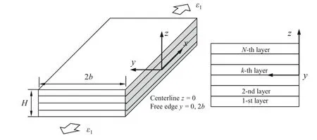
Fig.1 Geometry of composite laminate and its coordinate system

where the matrix S is the generalized compliance matrix. The temperature induced strain εtcan be calculated by the product of thermal expansion coefficients and temperature change as follows

In Eq.(1),the matrix form of linear constitutive relation contains six rows,including six strain and stress components. From the first row,we can calculate the stress component
σ1,which is expressed in terms of ε1and other five stress components as follows

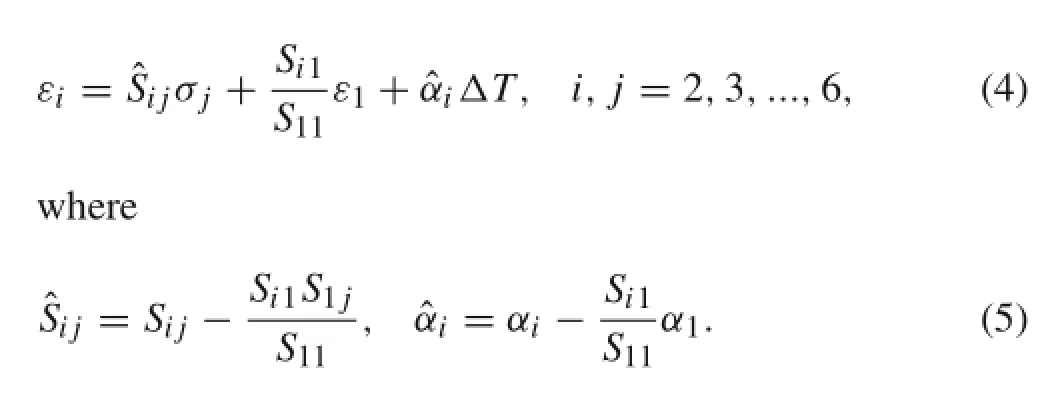
Substituting Eq.(3)into Eq.(1),the strains,exceptε1,can be expressed in terms of materials properties,ε1and six stress components.
The special case in which stresses and displacements are independent of length is the well-known generalized plane deformation.Under this assumption,the equations of equilibrium have the following form in absence of body force.

Introducing the Lekhnitskiistress functions[38],F(η,ζ)and ψ(η,ζ),which satisfy the equilibrium equations of the plane strain state automatically.

where η=y/b,ζ=z/H are the nondimensional coordinates.
By using the principle of variable separation,the Lekhnitskii stress functions are divided into two types of individual functions called the in-plane stress function and out-of-plane stress function in this work,where the in-plane stress function is the function of y and the out-of-plane stress function is the function of z.They can be further expressed by the series functions as follows

where fi(η)and pi(η)denote the in-plane stress functions,and gi(ζ)denote the out-of-plane stress function.The superscript I in Eq.(8)denotes the first order of differentiation.It isworth noting thatthe defined terminologies,in-plane stress function and out-of-plane stress function,differ from the terminologies of in-plane stress and out-of-plane stress in the following sections.
A Ritz-type solution method is developed for solving the localstresses in composite laminates in this work.Therefore,we firstly assume the out-of-plane stressfunction gi(ζ)asthe polynomial function and solve the in-plane stress functions(fi(η)and pi(η))via the virtualwork principle.The out-ofplane trial function is assumed simply as follows in which the second differentiation is guaranteed.

It should be noted that the pre-assumed out-of-plane trial function does not satisfy the required traction-free boundary conditions,where σ3=σ4=σ5=0 at ζ=±1/2. For the extended Kantorovich method,satisfying boundary conditions for initial trial function is not mandatory since the boundary conditions and continuity conditions will be enforced in each process.Thus,the accuracy of stress distributions can be improved while satisfying the boundary and continuity conditions during the iterations.
For static stress analysis of an elastic body,the complementary strain energy of symmetrically layered laminates subjected to uniaxial tensile load is given by

Substituting Eqs.(4)and(7)into Eq.(10),and with the help of Eqs.(8)and(9),conducting integration by partsand applying the traction-free boundary conditions,the governing equation can be obtained in the matrix form.

where the coefficients A(4),A(2),A(0),B(2),B(0),C(2),and C(0),listed below,are n by n matrices,which are expressed in terms of material properties and geometric dimensions. The unknown in-plane functions f={f}and p={p}are n dimensional vectors.The superscripts IV and II represent the fourth and second derivatives with respect to η.
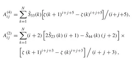

where N is the numberoflayers.The solutions to the governing equation can be obtained by solving ordinary differential equations with homogeneous solutions and a particular solution.Firstly,we assume the homogeneous solutions as

where the vectors vfand vpconsistofcoefficients appearing in the homogeneous solutions,and λ is the factor of exponential function.
Substituting Eq.(13)into Eq.(11)yields the following equations.


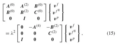
where λ2are the eigenvalues andare the eigenvectors.We know that when the local stresses concentrate near the free edges with a short distance and decrease in the interior region,the negative roots of eigenvalues are selected.Therefore,after solving the eigenproblem,the homogeneous solutions can be expressed as the following equations

where t={t}and the constant t is to be determined by boundary conditions at the free edge.
The particular solution can be obtained by considering the in-plane stress functions as constants.Therefore,all their derivatives vanish in the governing equationsand the remaining terms can be written as the following two equations.

Here,r={r}and s={s}.The final step is to determine the constant t appearing in the homogeneous solutions by enforcing the free edge boundary conditions(σ2=σ4= σ6=0,at η=0)that yields the following equations

Once the in-plane stress functions are obtained from the governing equations,the stress components can be obtained via substituting the solutions and out-of-plane stress function into the Lekhnitskii stress functions.


2.2Iterative formulations
The extended Kantorovich method requiresiterative processes to improve the accuracy of local stress distributions.Therefore,from the second process,the stress function based approach is repeated and the solution procedure is same.The difference is that the out-of-plane stress function is unknown and to be calculated in the second process,while the in-plane stress function are adopted from the results of first process. It should be noted that the out-of-plane stress function in the second process is assumed to be layerwise function,and the continuity conditions are enforced to guarantee the continuity of stresses along the thickness.The third process is as same as the first process,and therefore,for the sake of brevity,will not be introduced here.
The solution procedure for the second process is the same as the first process.The principle of complementary virtual work is applied again that yields the following governing equation

where the coefficients D(4)(k),D(2)(k),D(0)(k),and X(k)are expressed in terms of material constants,geometries,and inplane stress functions
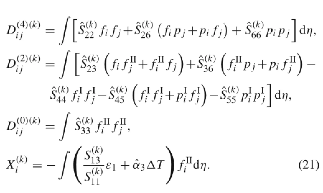
Equation(20)is the fourth order ordinary differential equation.Therefore,we assume the homogeneous solutions as

where vg(k)is the coefficient and μ(k)contains the factors of exponential functions.
Substituting the homogeneous solution into the governing equation,it results in the following equation


where the constant b(k)is to be calculated from the boundary conditions as well.
The particularsolutions g(k)(P)are calculated similarly by considering the out-of-plane stressfunction as constantin the governing equation resulting in the following equation.

The final step is to determine the constant b(k)appearing in the homogeneous solutions by means of the traction-free boundary conditions at the top and bottom surfaces,as well as the continuity conditions at the layer interfaces.

Equation(26)results in the following relations for the outof-plane stress functions with the help of Lekhnitskii stress functions.
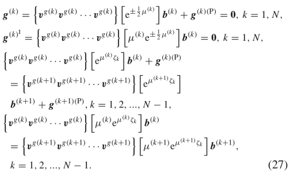
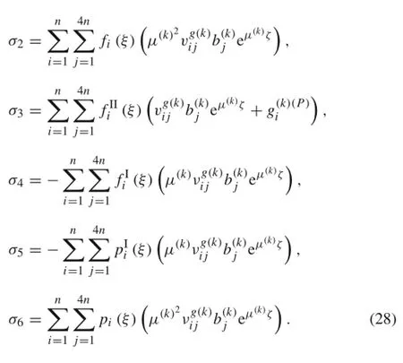
Once the out-of-plane stress function is solved,all stress components from the second process can be expressed by the following equations.
3 Results and discussion
Based on the mathematical formulations introduced in this work,a computer program was developed to study the local stresses in symmetrically layered composite laminates with finite dimensions subjected to uniaxial tensile strain load.It is assumed that the laminates have total thickness H and inplane length 2b,which is equivalent to four times the total thickness,shown in Fig.1.Each of the composite layers is of equal thickness,h=0.5 mm,and has orthotropic material properties with different material orientations.The mechanical properties of each graphite/epoxy lamina are given by[39]

Forverification,the 3DFEManalysis is conducted by means of commercial package ANSYS to compare the numerical results with those of the proposed approach,using solid 64 element for composite layers considering the generalized material properties.In the FEM analysis,the laminate has a length of ten times the width to express effectively the plane strain state.The clamped boundary conditions are applied to both ends of the laminate.The results are extracted at the middle of the laminate where the boundary effect has decayed.It should be noted that the FEM analysis requires very fine mesh,and refine at the free edges and layer interfaces to achieve accurate localized stress distributions,asshown in Fig.2.Therefore,the element numbers used in length,width,and each individual layer thickness are 50,30,and 20,respectively,resulting in a huge number of degree of freedoms(DOFs).Thus,it is computationally much more expensive when using the 3D FEM analysis.Without loss of generality,various layup configurations are considered in the present study.
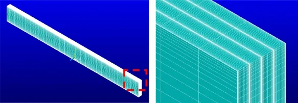
Fig.2 Finite element modeling of composite laminate with mesh
3.1Convergence study
The solution convergence is related to the number of terms in the series functions and the number of iterations for the stress function based extended Kantorovich method.These two factors will be examined in this subsection by considering a cross-ply laminate([0/90]s)subjected to uniaxialtensile strain load to show the validity and accuracy of the present method.To test the reliability of the analysis,the results are compared with those obtained by 3D FEM.Once the reliability of the present method has been successfully proved,further cases will be studied with various layup configurations.
Figures 3 and 4 present two stages of convergence for the free edge(y/b=0)normal stress σ3in[0/90]slaminate subjected to 1%uniaxial tensile strain load for term numbers and iteration numbers,respectively.These two figures demonstrate that with the fixed term number 4,it cannot predict the free edge normal stress accurately until the fifth iteration,where the interfaces of stress concentration can be accurately predicted.With the fixed iteration number 5,convergent results can be achieved when using four terms.The 3D FEM results are also given and compared with the proposed method.It is found that the FEM results follow the same tendency with the presentresults.Although there exists the difference of magnitude for the free edge stress because FEM underestimates the stress concentration at the interface of 0/90 layers,such difference is still tolerable and the correctness of the proposed method can be proved.Therefore,it can be concluded that using four terms and five iterations,
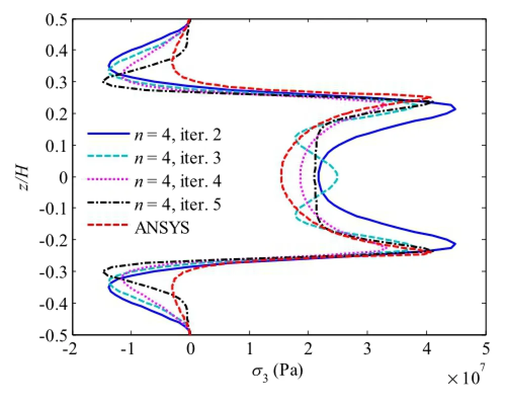
Fig.3 Convergence of free edge normal stress σ3in[0/90]slaminate under 1%uniaxial tensile strain,n=4,iters.2-5,where y/b=0
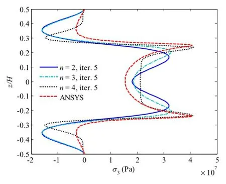
Fig.4 Convergence of free edge normal stress σ3in[0/90]slaminate under 1%uniaxial tensile strain,n=2-4,iter.5,where y/b=0
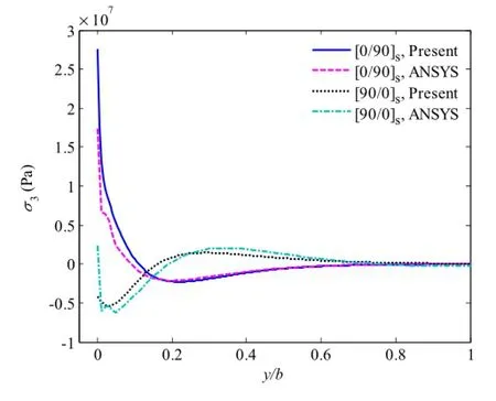
Fig.5 Interlaminar normal stress σ3in[0/90]sand[90/0]slaminates under 1%uniaxial tensile strain,where z/H=1/4
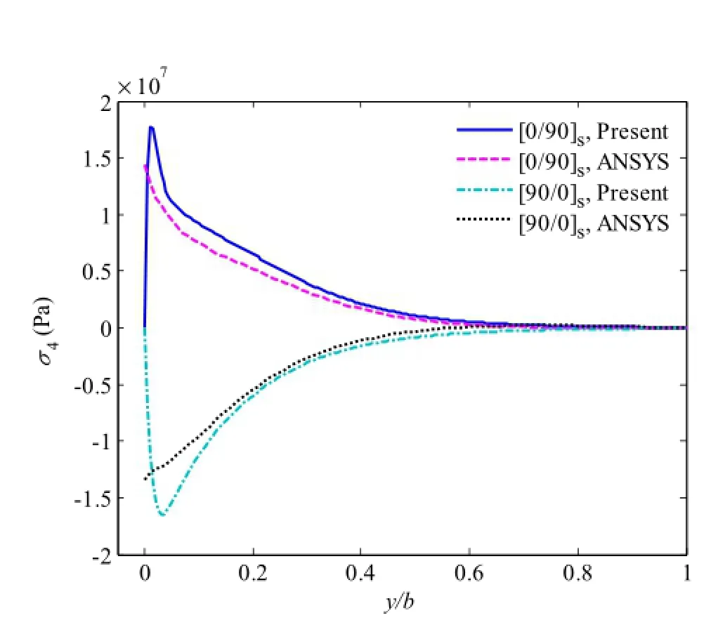
Fig.6 Interlaminar shear stress σ4in[0/90]sand[90/0]slaminates under 1%uniaxial tensile strain,where z/H=1/4
the accuracy can be guaranteed for the proposed method.It should be noted thatthe initialpolynomialassumption forthe out-of-plane stress function is arbitrary and does not satisfy boundary conditions.However,the free edge normal stress satisfies the traction-free boundary condition at both top and bottom surfaces,where the boundary conditions are enforced during the iterative processes.Moreover,the present method takes 3 s to solve a single case on an IntelCore i7(3.60 GHz)processor,whereas the computational time for the 3D FEM is longer than 5 min.Although the 3D FEM analysis can deal with the problem of complicated geometry and boundary conditions,the proposed extended Kantorovich method is computationally much more efficient than the 3D FEM for solving the local stresses in such symmetrically layered laminated structures.
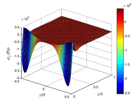
Fig.7(Color online)Distribution of interlaminar normal stress σ3 along the width in[0/90]slaminate under 1%uniaxial tensile strain,where z/H=1/4
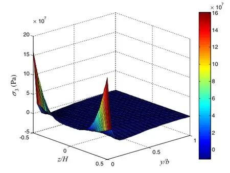
Fig.8(Color online)Distribution of interlaminar normal stress σ3 along the width in[90/0]slaminate under 1%uniaxial tensile strain,where z/H=1/4
3.2Case study
In this subsection,various layup configurations will be considered to study the local stresses in composite laminates in the interior region and at vicinity of the free edges.Since the previousconvergence study has already proved thatwith four terms and five iterations convergent results can be achieved,the following case study will use four terms and five iterations.The first example is two cross-ply laminates([0/90]sand[90/0]s)which are subjected to 1%uniaxial tensile strain load.The in-plane distribution of interlaminar normal stress σ3and shear stress σ4are shown in Figs.5 and 6 together with the FEM results.For both cross-ply stacking sequences,the large positive normal stress σ3concentrates at the free edge,where y/b=0,and vanishes in the interior region.This positive peeling stress could lead to the underly-ing delamination failure during the service life of composite laminates.The resultsare also wellvalidated by the 3DFEM,except for the difference at the free edge.This is because the FEM normally underestimates the peak values even using very fine mesh.For the shear stress σ4,the proposed method satisfies the prescribed stress boundary condition at the free edge and presents large stress values near the free edge. However,the FEM does not satisfy the free edge boundary condition for the shear stress σ4.The normal stress distributions along the width are shown in Figs.7 and 8 for[0/90]slaminate and[90/0]slaminate,respectively.These two graphs indicate that the stress vary significantly near the free edge along the z axisand converge in the interiorregions.Itisnoted here,the stress distribution is restricted to the cross-section of the laminate that is independent of the longitudinal axis. Thisresultwellrevealsthe edge-effectofcomposite laminate caused by the mismatch ofmechanicalproperties in adjacent layers.
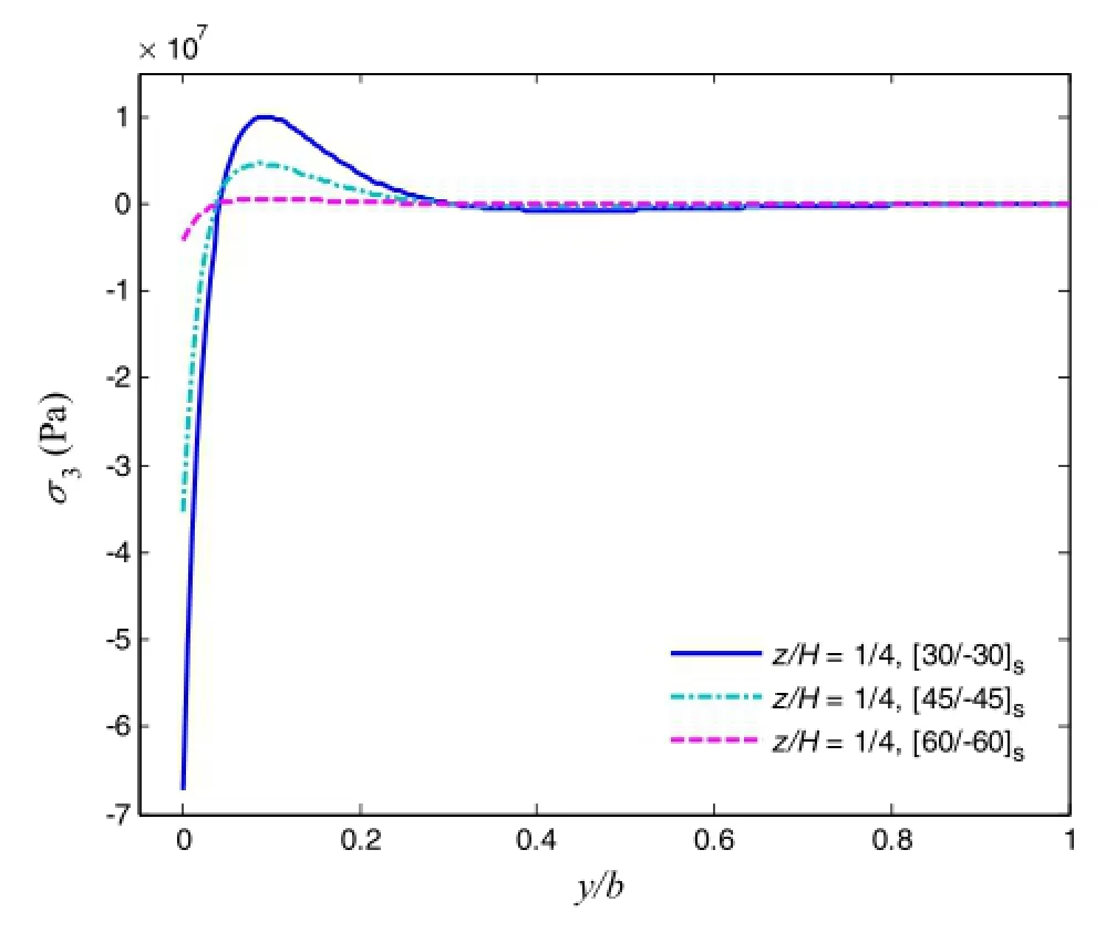
Fig.9 Interlaminar normal stress σ3in[30/-30]s,[45/-45]s,and[60/-60]slaminates under 1%uniaxial tensile strain,where z/H=1/4
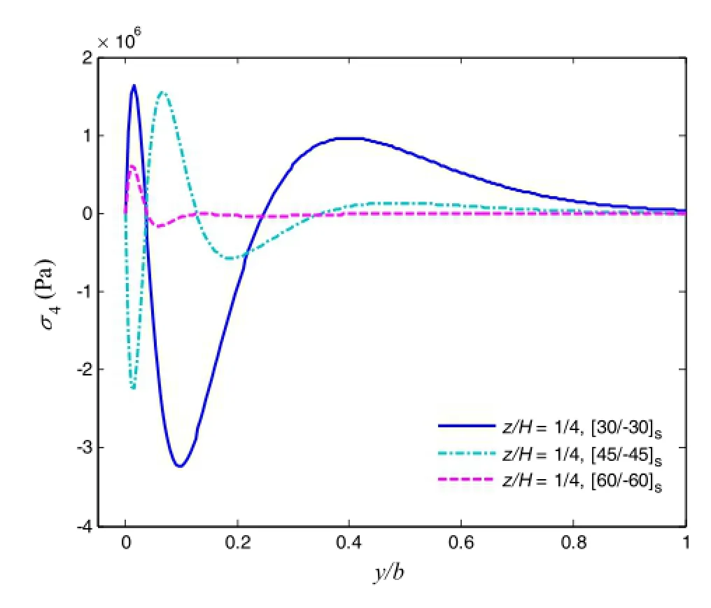
Fig.10 Interlaminar shear stress σ4in [30/-30]s,[45/-45]s,and[60/-60]slaminates under 1%uniaxial tensile strain,where z/H=1/4

Fig.11 Interlaminar shear stress σ5in[30/-30]s,[45/-45]s,and[60/-60]slaminates under 1%uniaxial tensile strain,where z/H=1/4
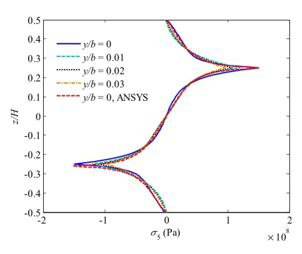
Fig.12 Free edge shear stress σ5in[45/-45]slaminate under 1% uniaxial tensile strain,where y/b=0,0.01,0.02,and 0.03

Fig.13 Interlaminar normal stress σ3in[0/90/45/-45]slaminate under 1%uniaxial tensile strain,where z/H=3/8,2/8,and 1/8

Fig.14 Interlaminar shear stress σ4in[0/90/45/-45]slaminate under 1%uniaxial tensile strain,where z/H=3/8,2/8,and 1/8
Next,three angle-ply cases([30/-30]s,[45/-45]s,and[60/-60]s)are investigated for the local stresses subjected to 1%uniaxial tensile strain load,where the in-plane stress distributions are shown in Figs.9,10,and 11,at the interface of z/H=1/4.For the normal stress σ3distribution,shown in Fig.9,it presents negative peak value at the free edge,and increasing the fiber orientations rapidly increases the magnitude of the free edge value.The shear stress σ4,shown in Fig.10,satisfies the boundary condition as well,and oscillates near the free edge and vanishes in the interior region.It can be seen that by changing the fiber orientation and layup stacking sequence of each layer,the local stress distributions can be significantly changed atthe layerinterfaces.The angle-ply cases can sustain large shear stress σ5at the free edge due to the fiber orientations,shown in Fig.11,while cross-ply laminate cannot.It is seen that[30/-30]slaminate presents the largest magnitude of σ5at the free edge among three cases.To examine the σ5distribution along the thickness and at the vicinity of the free edge,we provide the σ5distribution in[45/-45]slaminate through the thickness for four positions,where y/b=0,0.01,0.02,and 0.03,as shown in Fig.12.The interfacial value decreases gradually when approaching the interior region.The result of FEM at y/b=0 also shows excellent agreement with the proposed method.[0/90/45/-45]slaminate isinvestigated as well,where the inplane stress distributions are shown in Figs.13,14 and 15 and the out-of-plane stressdistributions are shown in Figs.16,17,and 18.For this case,the local stresses at various interfaces(z/H=3/8,2/8,and 1/8)and positions at the vicinity of free edge(y/b=0.0.01,0.02,and 0.03)are examined.For the inplane interlaminar stress distributions,it can be concluded that the stress concentration is found near the free edge at all interfaces,although there exists the difference of magnitude. Furthermore,the out-of-plane free edge stress distributions show thatthe stressmagnitude decreaseswhen increasing the value of y/b.Forexample,the peak value ofσ3atthe position y/b of 0 is almost 25%larger than that at the position y/b of 0.03.This indicates that the stress decays very fast and concentrates at the free edge only within a short distance.

Fig.15 Interlaminar shear stress σ5in[0/90/45/-45]slaminate under 1%uniaxial tensile strain,where z/H=3/8,2/8,and 1/8
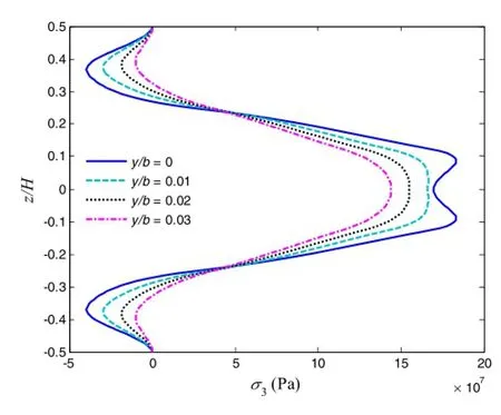
Fig.16 Free edge normal stress σ3in[0/90/45/-45]slaminate under 1%uniaxial tensile strain,where y/b=0,0.01,0.02,and 0.03
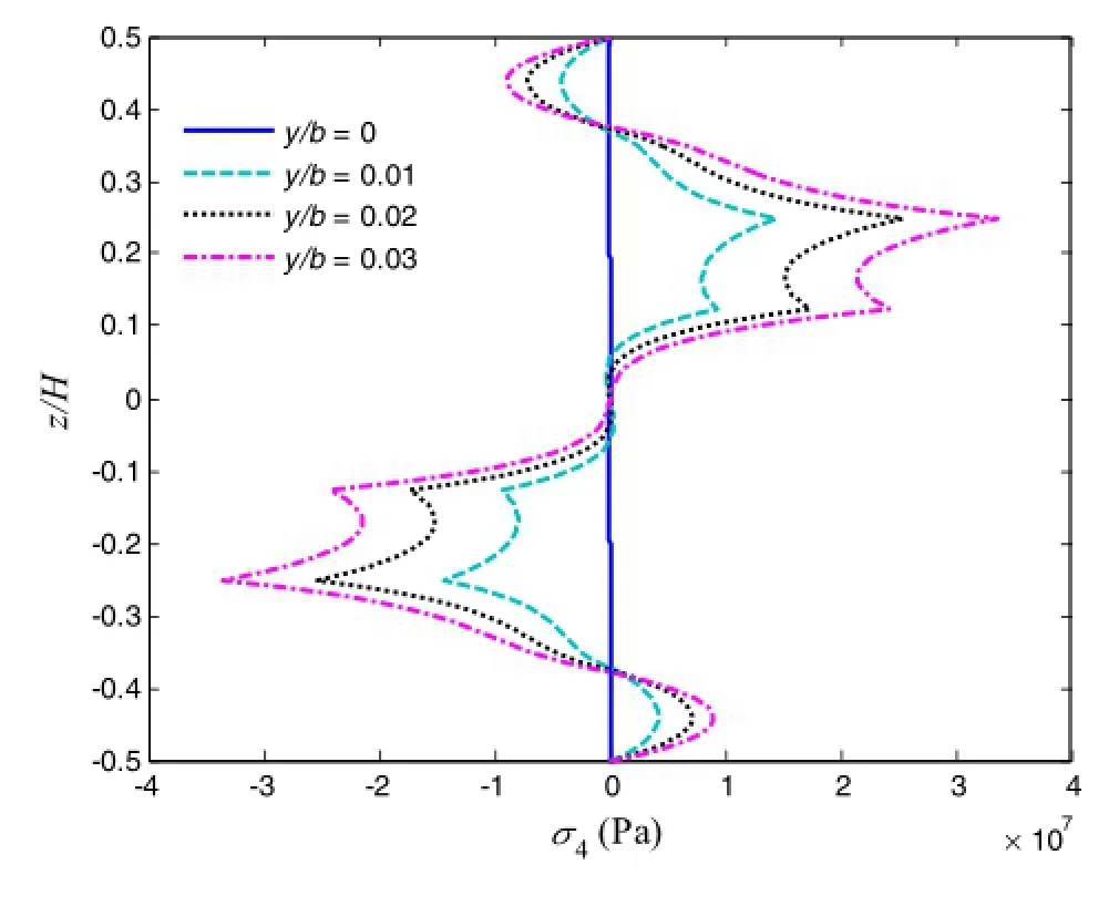
Fig.17 Free edge normal stress σ3 in[0/90/45/-45]s laminate under 1%uniaxial tensile strain,where y/b=0,0.01,0.02,and 0.03

Fig.18 Free edge normal stress σ3in[0/90/45/-45]slaminate under 1%uniaxial tensile strain,where y/b=0,0.01,0.02,and 0.03
4 Conclusions
In this study,the local stresses in composite laminate with finite dimensions are studied by means of the extended Kantorovich method upon the polynomial stress functions.The symmetrically layered laminates with various layup configurations are considered for the numerical analysis under the uniaxial tensile load.The stress distributions satisfy the traction-free boundary conditions as well as the free edge boundary conditions,although the pre-assumed polynomial assumption is arbitrary.The free edge effect is clearly revealed in this work for both the in-plane stress distributions and out-of-plane stress distributions.The effectiveness and accuracy of the proposed method in investigating the local stresses are demonstrated by comparing those results of 3D FEM.The convergence study is also performed to investigate the effect of term number in the initially assumed out-of-plane stress function and iteration numberon the convergence.Although increasing the termnumberimprovesthe accuracy of the results,the desired convergent results can be obtained by using only four terms in this work.Finally,several numerical examples are presented to study the local stress distributions based on the proposed methodology.The results show that the present methodology can be used as an efficient tool in the initial design of composite laminated structures to compute the local stresses at the interfaces and at the vicinity of free edges to control the local stresses or optimize the layup stacking sequences.
Acknowledgments This work was supported by the National Natural Science Foundation of China(Grants 11372145,11372146,and 11272161),the State Key Laboratory of Mechanics and Control of Mechanical Structures(Nanjing University of Aeronautics and astronautics)(Grant MCMS-0516Y01),Zhejiang Provincial Top Key Discipline of Mechanics Open Foundation(Grant xklx1601),and the K.C.Wong Magna Fund through Ningbo University.
1.Herakovich,C.T.:Mechanics of composites:a historical review. Mech.Res.Commun.41,1-20(2012)
2.Wang,S.S.,Choi,I.:Boundary-layer effects in composite laminates:part 1-free-edge stress singularities.J.Appl.Mech.49,541-548(1982)
3.Wang,S.S.,Choi,I.:Boundary-layer effects in composite laminates:part 2-free-edge stress solutions and basic characteristics. J.Appl.Mech.49,549-560(1982)
4.Spilker,R.L.,Chou,S.C.:Edge effects in symmetric composite laminates:importance of satisfying the traction-free-edge condition.J.Compos.Mater.14,2-20(1980)
5.Ghugal,Y.M.,Shimpi,R.P.:A review of refined shear deformation theories of isotropic and anisotropic laminated plates.J.Reinf. Plast.Compos.21,775-813(2002)
6.Kassapoglou,C.,Lagace,P.A.:An efficientmethod forthe calculation ofinterlaminarstressesin composite materials.J.Appl.Mech. 53,744-750(1986)
7.Zhu,C.,Lam,Y.C.:A Rayleigh-Ritz solution for local stresses in composite laminates.Compos.Sci.Technol.58,447-461(1998)
8.Konieczny,S.,Wo´zniak,C.:Corrected 2D-theories for composite plates.Acta Mech.103,145-155(1994)
9.Wang,Y.Y.,Lam,K.Y.,Liu,G.R.etal.:Astrip elementmethod for bending analysis of orthotropic plates.JSME Int.J.40,398-406(1997)
10.Kapuria,S.,Dube,G.P.,Dumir,P.C.:First-ordersheardeformation theory solution for a circular piezoelectric composite plate under axisymmetric load.Smart Mater.Struct.12,417(2003)
11.Thai,H.T.,Choi,D.H.:A simple first-order shear deformation theory for the bending and free vibration analysis of functionally graded plates.Compos.Struct.101,332-340(2013)
12.Reddy,J.N.,Liu,C.F.:A higher-order shear deformation theory of laminated elastic shells.Int.J.Eng.Sci.23,319-330(1985)
13.Cho,M.,Parmerter,R.:Efficient higher order composite plate theory for general lamination configurations.AIAA J.31,1299-1306(1993)
14.Chattopadhyay,A.,Gu,H.:New higher order plate theory in modeling delamination buckling of composite laminates.AIAA J.32,1709-1716(1994)
15.Robbins,D.H.,Reddy,J.N.:Modelling of thick composites using a layerwise laminate theory.Int.J.Numer.Methods Eng.36,655-677(1993)
16.Zhou,X.,Chattopadhyay,A.,Kim,H.S.:An efficient layerwise shear-deformation theory and finite element implementation.J. Reinf.Plast.Compos.23,131-152(2004)
17.Oh,J.H.,Cho,M.,Kim,J.S.:Enhanced lower-order shear deformation theory for fully coupled electro-thermo-mechanical smart laminated plates.Smart Mater.Struct.16,2229-2241(2007)
18.Kim,J.S.:Free vibration of laminated and sandwich plates using enhanced plate theories.J.Sound Vib.308,268-286(2007)
19.Mitchell,J.A.,Reddy,J.N.:A refined hybrid plate theory for composite laminates with piezoelectric laminae.Int.J.Solids Struct. 32,2345-2367(1995)
20.Detwiler,D.T.,Shen,M.H.,Venkayya,V.B.:Finite element analysis of laminated composite structures containing distributed piezoelectric actuators and sensors.Finite Elem.Anal.Des.20,87-100(1995)
21.Artel,J.,Becker,W.:Coupled and uncoupled analyses of piezoelectric free-edge effect in laminated plates.Compos.Struct.69,329-335(2005)
22.Oh,J.H.,Cho,M.,Kim,J.S.:Buckling analysis of a composite shell with multiple delaminations based on a higher order zig-zag theory.Finite Elem.Anal.Des.44,675-685(2008)
23.Lee,J.,Cho,M.,Kim,H.S.:Bending analysis of a laminated composite patch considering the free-edge effect using a stress-based equivalentsingle-layercomposite model.Int.J.Mech.Sci.53,606-616(2011)
24.Kim,H.S.,Lee,J.,Cho,M.:Free-edge interlaminar stress analysis of composite laminates using interface modeling.J.Eng.Mech. 138,973-983(2012)
25.Huang,B.,Kim,H.S.:Free-edge interlaminar stress analysis of piezo-bonded composite laminates under symmetric electric excitation.Int.J.Solids Struct.51,1246-1252(2014)
26.Kim,H.S.,Cho,M.,Lee,J.,etal.:Three dimensionalstressanalysis of a composite patch using stress functions.Int.J.Mech.Sci.52,1646-1659(2010)
27.Flanagan,G.:An efficient stress function approximation for the free-edge stresses in laminates.Int.J.Solids Struct.31,941-952(1994)
28.Yin,W.L.:Free-edge effects in anisotropic laminates under extension,bending and twisting,Part I:a stress-function-based variational approach.J.Appl.Mech.61,410-415(1994)
29.Yin,W.L.:Free-edge effects in anisotropic laminates under extension,bending,and twisting,Part II:eigenfunction analysis and the resultsforsymmetriclaminates.J.Appl.Mech.61,416-421(1994)
30.Kerr,A.D.,Alexander,H.:An application of the extended Kantorovich method to the stress analysis of a clamped rectangular plate.Acta Mech.6,180-196(1968)
31.Kerr,A.D.:An extended Kantorovich method for the solution of eigenvalue problems.Int.J.Solids Struct.5,559-572(1969)
32.Tahani,M.,Andakhshideh,A.:Interlaminar stresses in thick rectangular laminated plates with arbitrary laminations and boundary conditions under transverse loads.Compos.Struct.94,1793-1804(2012)
33.Tahani,M.,Naserian-Nik,A.M.:Bending analysis of piezolaminated rectangular plates under electromechanical loadings using multi-term extended Kantorovich method.Mech.Adv.Mater. Struct.20,415-433(2013)
34.Kapuria,S.,Kumari,P.:Extended Kantorovich method for coupled piezoelasticity solution ofpiezolaminated plates showing edge effects.Proc.R.Soc.A Math.Phys.469,20120565(2013)
35.Kapuria,S.,Kumari,P.:Extended Kantorovich method for threedimensional elasticity solution of laminated composite structures in cylindrical bending.Journal of Applied Mechanics 78,1774-1800(2011)
36.Cho,M.,Kim,H.S.:Iterative free-edge stressanalysisofcomposite laminates underextension,bending,twisting and thermalloadings. Int.J.Solids Struct.37,435-459(2000)
37.Kim,H.S.,Cho,M.,Kim,G.I.:Free-edge strength analysisin composite laminates by the extended Kantorovich method.Compos. Struct.49,229-235(2000)
38.Lekhnitskii,S.G.:Theory of Elasticity of an Anisotropic Body. Holden-Day,San Francisco(1963)
39.Tahani,M.,Nosier,A.:Three-dimensional interlaminar stress analysis at free edges of general cross-ply composite laminates. Mater.Des.24,121-130(2003)
29 October 2015/Revised:9 March 2016/Accepted:12 April 2016/Published online:15 June 2016
©The Chinese Society of Theoretical and Applied Mechanics;Institute of Mechanics,Chinese Academy of Sciences and Springer-Verlag Berlin Heidelberg 2016
- Acta Mechanica Sinica的其它文章
- Gradient systems and mechanical systems
- Contact force and mechanical loss of multistage cable under tension and bending
- Numerical study on the deformation of soil stratum and vertical wells with gas hydrate dissociation
- Reliability assessment on interfacial failure of thermal barrier coatings
- Nonlinear integral resonant controller for vibration reduction in nonlinear systems
- Numerical analysis of stress distribution in the upper arm tissues under an inflatable cuff:Implications for noninvasive blood pressure measurement

