Numerical study on the deformation of soil stratum and vertical wells with gas hydrate dissociation
Xudong Chen·Xuhui Zhang·Xiaobing Lu·Wei Wei·Yaohong Shi
RESEARCH PAPER
Numerical study on the deformation of soil stratum and vertical wells with gas hydrate dissociation
Xudong Chen1·Xuhui Zhang1·Xiaobing Lu1·Wei Wei2·Yaohong Shi3
Gas hydrate(GH)dissociates owing to thermal injection or pressure reduction from the well in gas/oil or GH exploitation.GH dissociation leads to,for example,decreases in soil strength,engineering failures such as wellbore instabilities,and marine landslides.The FLAC3D software was used to analyze the deformation of the soil stratum and vertical wells with GH dissociation.The effects of Young’s modulus,internal friction angle,cohesion of the GH layer after dissociation,and the thickness of the GH layer on the deformation of soils were studied.It is shown that the maximum displacement in the whole soil stratum occurs at the interface between the GH layer and the overlayer.The deformation ofthe soilstratumand wellsincreases with decreases in the modulus,internal friction angle,and cohesion after GH dissociation.The increase in thickness of the GH layer enlarges the deformation of the soil stratum and wells with GH dissociation.The hydrostatic pressure increases the settlement of the soil stratum,while constraining horizontal displacement.The interaction between two wells becomes significant when the affected zone around each well exceeds half the length of the GH dissociation zone.
✉ Xuhui Zhang zhangxuhui@imech.ac.cn
1Institute of Mechanics,Chinese Academy of Sciences,Beijing 100190,China
2Research Institute of Petroleum Exploration and Development-Langfang,Langfang 065007,China
3Marine Environmental and Engineering Geological Survey,Guangzhou Marine Geological Survey,Guangzhou 510075,China
Gas hydrate·Dissociation·FLAC3D·Soil stratum·Well
1 Introduction
A hydrate is a crystalline icelike solid composed of guest molecules such as methane,carbon dioxide,tetrahydrofuran,sulfur dioxide,and water molecules.Gas hydrate(GH)is distributed extensively in permafrostand marine strata under sufficiently high pressure and low temperature conditions[1,2].
Most previous studies focused on the exploitation of GH[3,4].However,GH dissociation reduces the strength of hydrate-bearing soils(HBS)and leads to hazards such as marine landslides on a large engineering scale and instabilities of exploitation wells on a local small scale[5-10].The Storegga slide in Norway[11,12],the Cape Fear slide on the east coast of the USA,the landslide on the continental shelf of West Africa[13,14],and other landslides[15]in marine conditions were regarded as the result of GH dissociation. The 2010 Deepwater Horizon explosion in the Gulf of Mexico might have been caused by GH dissociation since the drilling rig was in the stratum where the pressure and temperature are suitable for hydrate formation[16].However,the deformation of the soil stratum and vertical wells with GH dissociation is poorly understood.
Wang et al.[17]investigated the responses of a well in the soil stratum with GH dissociation.That study focused on the effects of the degree of GH dissociation on well deformation.Cai et al[18].proposed a model to describe the thermo-hydro-mechanical coupling behavior of unsaturated soils.Sultan et al.[19]presented a method to simulate excesspore pressure using a state equation underno fluid dis-sipation and no-volume change of soils.Then gas-dissolved water filled the pores of the soil skeleton,leading to geological hazards such as fractures or even gas outburst under unloading conditions.Iwai et al.[20]simulated the coupled behaviors ofheattransfer,phase transformation ofhydrate to gas and water,soil deformation,and seepage and presented the main factors for ground stability during hydrate dissociation.Zhang et al.[10,21]studied the layer fracture and gas outburst in the stratum during/after GH dissociation using both experimentaland theoreticalmethods and presented the mechanisms of excess pore fluid pressure-induced soil failures.However,itisstillnotclearwhatthe criticalcondition of soilfailure is during GHdissociation with a rapid dissipation of fluids in the pores,which is important for the evaluation of GH exploitation.
This paper aims to examine the deformation of the soil stratumand verticalwellsduring GHdissociation.The development of deformation in the soil stratum and vertical wells with GH dissociation was simulated using FLAC3D software,decoupled with heat transfer and fluid seepage.The elastic-plastic constitutive model and the Mohr-Coulomb criterion were adopted to describe the deformation and failure behaviors ofsoil.The effects ofmodulus,internalfriction angle,cohesion,and thickness of the GH layer on the deformation were investigated. hydrate dissociation zone and the fluid seepage are two slow physical effects,and analytical solutions are obtained[10]. Here,the problem is simplified such that the soil deformation and failure complete instantaneously underthe given GH dissociation zone,pore fluid pressure,and stress status.
FLAC3D is a kind of numerical software developed on the basis ofcontinuum mechanics forgeotechnicalengineering problems.Using a rapid Lagrange difference method,the deformation and failure of soil,especially a large deformation,can be analyzed,even coupling with the physical processes of heat transfer and multiphase flow in porous media.The applicability of FLAC3D was validated by centrifugal test on the stratum instability of a 90 m slope during hydrate dissociation[22].Hence,numerical simulations on stratum instabilities during hydrate dissociation were conducted using FLAC3D on large engineering scales.
Here the responses of the HBS were simulated with the length of the dissociation zone expanded from 50 to 250 m. The responses of the soils were affected by the relative size of the dissociation zone,the relative thickness of the GH layer,the relative modulus,and the shearstrength coefficients of the GH layer following dissociation to before dissociation[9,22].Here,decoupled analysis was conducted,and the deformation and soil failure were simulated following complete hydrate dissociation.The present constitutive model describes the soil mechanical behaviors of hydrate-bearing sediments and sediments following hydrate dissociation.An elastic-plastic stress-strain relationship was adopted as the constitutive model in the numerical simulations.The shear strength was described by the Mohr-Coulomb yielding criterion.The elastic deformation wasconsidered tillthe soilshear strength was reached.The elastic modulus and shearstrength ofthe soillayers(hydrate layerand overlayer)were obtained in triaxialtests ofhydrate-bearing sediments before and after hydrate dissociation,and geological and geotechnical parameters were adopted referring to the drilling and welllogging results of the Dongsha hydrate area in the South China Sea(Table 1)[22,23].In the following simulation,three factorseffects of modulus,strength coefficients(internal friction angle and cohesion),and thickness of GHlayer-were investigated.
A sketch of the numerical model is shown in Fig.1.The size of the stratum was set as length×width=1000 m× 1000 m,the thickness of the GH layer was 25 m,the thickness of the overlayer was 200 m,and the slope was 15◦.The
2 Introduction of numerical model
GHdissociation starts and expands from a verticalwell(with hot fluid in the well as the heat source).Methane gas and water are released and assumed to drain rapidly,while the soil strength of the dissociation zone decreases significantly. Underthe weightofthe overlayerand hydrate layerfollowing GH dissociation,soil deformations develop.Plastic failure occurs when the dissociation zone expands to a criticalvalue,then soil failures,such as marine slides,will occur.In this problem,three main physical effects are involved,i.e.,heat transfer with GH dissociation,fluid seepage,and soil deformations and failures.The ratios of the three characteristic times are approximately 109:105:1,and the three physical processes can be solved by the decoupling method.The significance of decoupling is that the slowest heat transfer,the fluid seepage,and the most rapid soil deformation can be solved in order of the time sequence.The expansion of thebottom of the overlayer was glued to the GH layer,keeping the deformation continuous.The boundary conditions of the soil stratum were set as follows:the bottom was fully fixed,the lateral boundaries were normally fixed,and the surface was free.A well of size ϕ×t=0.4 m×0.02 m was set in the center of the model,passing through the soil layers vertically.The elastic modulus E of the well was 2×10¹¹Pa,and the Poisson’s ratio ν was 0.3.The well was regarded as a pile unit in FLAC3D to describe the deformation and interaction with the soil.

Table 1 Soil parameters

Fig.1 Sketch of numerical model
3 Results and discussions
3.1Development of deformation under different lengths of dissociation zone
3.1.1Development of settlement zone
Figure 2 shows the affected area of soil settlement when the length of the dissociation zone is 200m.With the expansion of the GH dissociation zone,the settlement zone expands in an approximately symmetrical way.
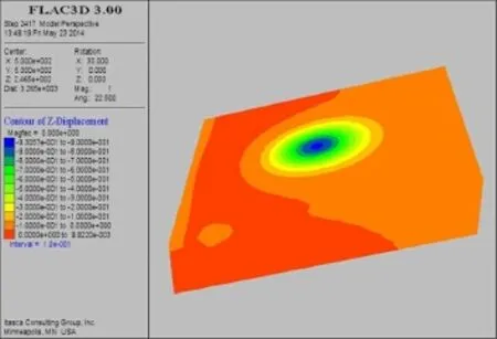
Fig.2(Color online)The affected zone
The largest settlement is located at the surface of the GH layer.The maximum settlement at the overlayer’s surface is located near the well and increases linearly with the expansion of the dissociation zone(Fig.3).The reason for this is that the strength of the GH layer supporting the overlayer decreases with GH dissociation.The soil settles and moves horizontally along the slope under gravity.The affected zone expands with the expansion of the dissociation zone(Fig.4).
It should be noted that in the following figures,A indicates the length of the affected zone,D1the size of the dissociation zone,H the thickness of the GH layer,h the thicknessofthe overlayer,wmaxthe maximumhorizontaldisplacement of the well,Szthe settlement at the surface of the overlayer,Sxthe horizontal displacement of soils,Szmaxthemaximum settlementatthe surface ofthe overlayer,z the verticalposition,and x the horizontalposition.The affected zone is defined as the zone where the ratio of settlement at the surface to the thickness of the overlayer exceeds 0.05%(s/h≥0.05%).
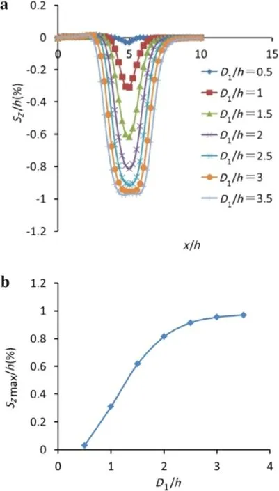
Fig.3 Developmentofsettlementwith expansion ofdissociation zone. a Settlement at surface.b Maximum settlement at surface
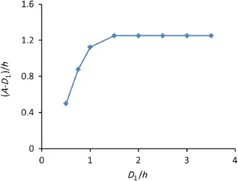
Fig.4 Development of affected zone with expansion of dissociation zone
3.1.2Horizontal displacement
Figure 5 shows the horizontal displacement of soils under a length of dissociation zone of 200 m.The data at the vertical sections of 300,400,450,550,600,and 700 m from the toe ofthe slope,respectively,are adopted fordiscussion.The direction of the horizontal displacements in the overlayer is differentfromthe dissociation centerline(coincidentwith the well)(x=500 m).Downward from the centerline,the soils move upward to the centerline,and the horizontal displacement increases with the decrease in the distance from the centerline,while above the centerline the soils move downward to the centerline.In the overlayer,soilsettlementoccurs with softening in the GH dissociation zone,pulling the soils to move toward the centerline.Under the constraint of an undissociated hydrate zone and lateral sides,the soils move toward the centerline,forming a funnel-shaped settlement zone,while in the GH layer,the settlement of the overlayer pushes the soil away from the centerline,mostly toward the toe of the slope.The settlement along the slope and squeezing ofthe soilleads to changes in the horizontaldisplacement along the depth.
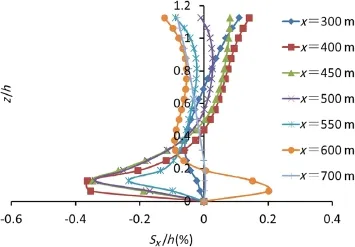
Fig.5 Development of horizontal displacement of soil stratum
3.1.3Displacement of vertical well

Fig.6 Horizontal displacement of well under different lengths of GH dissociation zone.a In vertical section.b Largest displacement

Table 2 Cases for numerical simulation
The well is supported by the soils.The deformation of the well increases with the increase in the displacement of the soils.In Fig.6a,the largest well’s displacement for each length of the dissociation zone is located at the interface between the overlayer and the GH layer and increases with the expansion of the dissociation zone.The main reason for this is that the displacement of the vertical well is caused by the soil deformation.Hence,the trend of the horizontal displacement of the well along the depth is consistent with the soil(Fig.5).The larger stiffness of the well leads to differences in the magnitude.The displacement is zero at the bottom owing to the fixed boundary condition,while the largestdisplacementis located atthe surface ofthe GHlayer. Owing to the inherent stiffness of the well and continuous elastic deformation,the horizontal displacement is upward. The inherent stiffness and the interaction force between the well and soil leads to changes in the deformation of the well along the depth.Figure 6b shows the largest horizontal displacements with different lengths of the dissociation zone. The magnitude of the changes decreases when the dissociation zone exceeds 100 m.This is because the supporting effect of the lateral sides on the well is reduced when the dissociation zone is smaller than 100 m.
3.2Effects of main factors on displacements of soil layer and well
The effects of the main factors,such as the modulus,internal friction angle,cohesion,and thickness of the GH layer,on the displacementofthe soillayerand wellare examined.The results obtained when the dissociation zone is under 200 m long are discussed.The cases in the numericalsimulation are listed in Table 2.
3.2.1Effect of modulus
Three moduli are considered here:105,70,and 35 MPa. The settlement increases with the decrease in the modulus.The maximum settlement decreases 30%and increases 80%when the modulus increases 50%and decreases 50%,respectively(Figs.7a and 7b).
The size of the affected zone decreases with increases in the modulus(Fig.7c).In addition,the horizontal displacement of the well develops with the modulus of the GH layer(Fig.7d).The largest horizontal displacement of the well increases 110%when the modulus decreases 50%.The well’s displacementis caused by the displacementin the over layer and the GH layer(Fig.7e).
3.2.2Effect of cohesion
Figure 8 presents the effect of the cohesion of the GH layer on the deformation of the soil layer and well.The deformation of the soil and well increases with the expansion of the dissociation zone and the decrease in cohesion;the change is slight even if the cohesion(much less than 106Pa)changes tenfold.This is because the term σtanϕ is on the order of 106,so the effect of the cohesion is smaller by at least one order of magnitude.
3.2.3Effect of internal friction angle
The larger the internal friction angle,the greater the strength of the soil layer.Thus,the deformation is limited for a large internal friction angle.Once the internal friction angle drops below 4◦,the deformation of both the soil layer and the well increases quite rapidly(Figs.9a and 9b).This indicates that the strength of the soil layer is controlled by the internal friction angle in these cases.When the internal friction angle is smaller than 4◦,the failure zone increases rapidly with decreases in the internal friction angle.While most soils are in an elastic state,the deformation changes slowly with a decrease in the internal friction angle when it is greater than 4◦.The plastic deformation zone and the affected zone increase with decreasesin the internalfriction angle(Fig.9c).
3.2.4Effect of GH thickness
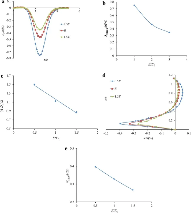
Fig.7 Effects of modulus on deformation of soil stratum and well.a Distribution of settlement at surface of overlayer.b Largest settlement.c Size of affected zone.d Horizontal deformation of well.e Largest horizontal deformation of well.E0in plots b,c,e is 70 MPa
Three GH thicknesses are adopted here:25,50,and 75 m(H/h=1/8,H/h=2/8,and H/h=3/8).Both the affected zone and the settlement increase with increases in the GH layer’s thickness.The affected zone is in a linear relationship with the thickness,while the settlementincreases slowly with increases in the thickness.The settlement of the GH layer is linear to the thickness after dissociation in the estimation of the consolidation(Fig.10).The overlayer can be regarded as a deep beam overlying the GH layer,and it deforms linearly with the deformation of the GH layer.The affected zone in the nondissociation zone is approximately constantwith increasesin the dissociation zone.Deformation is mainly related to the strength coefficients(internalfriction angle and cohesion)and the thickness of the overlayer using the limit equilibrium method.In the first stage,this zone increases with the dissociation zone because the failure zone in the overlayer is relatively small,and elastic deformation is dominant in a small dissociation zone.
The deformation of the well increases with the expansion ofthe dissociation zone(Fig.11).When the ratio ofthe length of the dissociation zone to the thickness of the over layer is less than 0.5,the maximum deformation increases more for the dimensionless thickness of the GH layer(the ratio of thickness of the GH layer to the thickness of the over layer)1/8 than 2/8 and 3/8.The change of the well’s deformation becomes slow with the expansion of the dissociation zone when the dimensionless thickness of the GH layer is less than 1/8(Fig.11).The supporting effect of the over layer to the well is dominant when the dimensionless thicknessof the GH layer H/h is small.The displacement of well is small similar to that of the GH layer in the small thickness. With the increase of H/h,the bearing force of GH layer to the well increases and the displacement of the GH layer increases with the expansion of the GH dissociation.

Fig.8 Effects of cohesion of GH layer on deformations of soils and well.a Maximum settlementatsurface ofoverlayer.b Maximum deformation
3.2.5Effect of well interaction
The effects amongst soils and two wells were studied.The distance between the two wells was 200 m.The deformation with two wells is the same as that with single well at the length of dissociation zone less than 50 m.Only when the length of dissociation zone is over 150 m,the deformation of the two wells is much different from the case of a single well.At a small length of dissociation zone,the dissociation zone around the two wells and the two affected zone foreach dissociation zone are independent.With the expansion of dissociation zone,the affected zones and dissociation zones connected,thus the bearing force of the un-dissociated zone to the wells becomes weaker,and the deformation becomes larger than that case of a single well.Figure 12 presents the deformation of the two wells and a comparison with the deformation under a single well condition.
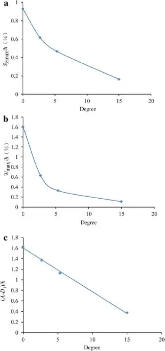
Fig.9 Deformations of soil stratum and well under different internal friction angles.a Largest settlement at surface.b Largest horizontal deformation of well.c Development of affected zone
3.2.6Effect of water depth

Fig.10 Effects of GH layer’s thickness on soil deformation.a Maximum deformation at surface.b Changes in affected zone
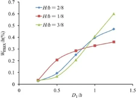
Fig.11 Effects of the GH layer’s thickness on the well’s maximum horizontal displacement
Three water depths were adopted,500,1000,and 1500 m,to study the effects of hydrostatic pressure.Generally,in hydrate formation,the overlayer is impermeable.Here,the increase in the waterdepth increasesthe totalstressofthe soil,while the pore fluid pressure in the hydrate layer is assumed to be irrelevantto the waterdepth,and the stiffnessofthe well is unchanged in the numerical simulation.Hence,in Fig.13, both the settlementand the affected zone increase with water depth.The reason for this is that the increase in water depth leads to an increase in hydrostatic pressure on the surface of the overlayer.The greater the water depth,the larger the deformation of soils.

Fig.12 Deformation oftwo wells and comparison with thatofa single well condition.a At a distance from slope to 400 m.b At a distance from slope to 600 m
Figure 14 shows the well’s deformation with GH dissociation atdifferentwaterdepths.The whole wellmoves toward the toe with the expansion of the dissociation zone at a water depth of 500 m.As the water depth increases to 1000 and 1500 m,an obvious inclination occurs with the expansion of the dissociation zone.The upper part of the well moves toward the top of the slope in the overlayer,while the lower partmoves toward to the toe ofthe slope in the GHlayer.The hydrostatic pressure atthe surface ofthe overlayerconstrains the horizontaldeformation ofthe soilstratumand wells while increasing the settlement of soils.Hence,the deformation of a well is much different from that without water pressure.
4 Conclusions
Responses of the soil stratum and vertical wells to GH dissociation were studied using FLAC3D software,and the geological and geotechnical conditions in the South China Sea were used as references to set up a numerical model. The effects of the length of the GH dissociation zone,modulus,internal friction angle,cohesion,and thickness of the GH layer on the displacement of the soil stratum and wells were analyzed.The main conclusions drawn are as follows:
(1)The relative affected zone in the overlayer expands with an increase in the dissociation zone while remaining almost constant after the thickness of the dissociation zone becomes twice that of the overlayer.Maximum settlement occurs at the surface of the GH dissociation zone and is in an approximately linear increase with the expansion of the GH dissociation zone.The maximum horizontal displacement of the soil stratum occurs at the interface between the GH layer and the overlayer.
(2)The deformation of the soil stratum and wells increases with decreases in the modulus following GH dissociation.The settlement of the soil stratum increases nonlinearly as the thickness of the GH layer increases. The length of the affected zone is approximately linear to its thickness.The soil deformation and the length of the affected zone increase with decreases in the internal friction angle owing to the development of a plastic failure zone.

Fig.14 Well deformation at different water depths.a hw=500 m. b hw=1000 m.c hw=1500 m.d Maximum deformation of well at z/h=1/8
(3)The interaction between two wells is negligible when the length of the dissociation zone around each well is less than one-fourth the distance between the wells and the affected zones are independent,while the interactionbecomes significant when the length of the dissociation zone is over one-half the distance between the two wells owing to the connection of the affected zones.
(4)Different water depths lead to different hydrostatic pressures on the surface ofthe overlayer.Both the settlement andthe affected zone increase with waterdepth,while the hydrostatic pressure constrains the horizontal displacement of the soil stratum and wells.The deformation of the soil stratum and wells is much different from that without water depth.
It is hoped that the results presented here will provide a reference for GH exploitation engineering in GH layers or gas exploitation under GH layers.
Acknowledgments Thisprojectwassupported by the NationalNatural Science Foundation of China(Grants 11272314,51239010,41376078),a joint project of the Chinese National Petroleum Corporation and the Chinese Academy of Sciences(Grant 2015A-4813),and a project of the China Geological Survey(Grant GZH201100311).
1.Sloan,E.D.:Clathrate Hydrates of Natural Gases.Marcel Dekker Inc.,New York(1998)
2.Riedel,M.,Bellefleur,G.,Dallimore,S.R.,et al.:Amplitude and frequency anomalies in regional 3D seismic data surrounding the Mallik 5L-38 research site,Mackenzie Delta,Northwest Territories,Canada.Geophysics 71,183-191(2006)
3.Sakamoto,Y.,Komai,T.,Kawamura,T.,et al.:Field scale simulation for the effect of relative permeability on dissociation and gas production behavior during depressurization process of methane hydrate in marine sediments.In:Proceedings of the ISOPE Ocean Mining Symposium,Lisben,Portugal(2007)
4.Sakamoto,Y.,Kakumoto,M.,Miyazaki,K.,etal.:Numericalstudy on dissociation of methane hydrate and gas production behavior in laboratory scale experimentsfordepressurization:numericalstudy on estimation of permeability in methane hydrate reservoir.Int.J. Offshore Polar Eng.19,124-134(2009)
5.Dickens,G.R.,Quinby-Hunt,M.S.:Methane hydrate stability in seawater.Geophys.Res.Lett.21,2115-2118(1994)
6.Milkov,A.V.:Worldwide distribution ofsubmarine mud volcanoes and associated gas hydrates.Mar.Geol.167,29-42(2000)
7.William,J.W.,Ingo,A.P.,William,F.W.,et al.:Physical properties and rock physics models of sediment containing natural and laboratory-formed methane NGH.J.Am.Miner.89,1221-1227(2004)
8.Xu,W.,Germanovich,L.N.:Excess pore pressure resulting from methane hydrate dissociation in marine sediments:A theoretical approach.J.Geophys.Res.111,B011104(2006).doi:10.1029/ 2004JB003600
9.Lu,X.B.,Wang,L.,Wang,S.Y.et al.:Instability of seabed and wells induced by NGH dissociation.In:Proceedings of the 20th InternationalOffshore and Polar Engineering Conference,Beijing,110-114(2010)
10.Zhang,X.H.,Lu,X.B.,Li,Q.P.:Formation of layered fracture and outburst during gas hydrate dissociation.J.Pet.Eng.Sci.76,212-216(2011)
11.Hovland,M.,Orange,D.,Bjorkum,P.A.et al.:NGH and seepseffects on slope stability.In:Proceedings of the 11th International Offshore and Polar Engineering Conference,Norway,471-476(2001)
12.Locat,J.,Lee,H.:Submarine landslide,advances and challenges. J.Can.Geotech.39,193-212(2002)
13.Kayer,R.E.,Lee,H.J.:Pleistocene slope instability of NGH-laden sedimenton the BeaufortSea Margin.J.Mar.Geotechnol.10,125-141(1991)
14.Sultan,N.,Cochonat,P.,Foucher,J.P.,et al.:Effect of NGHs melting on seafloorslope instability.J.Mar.Geol.213,379-401(2004)
15.Gilles,G.,David,G.,Aaleksandr,M.:Characterization of in situ elastic properties of NGH bearing sediments on the Blake Ridge. J.Geophys.Res.104,17781-17795(1999)
16.Sassoon,D.:Did Deep water methane hydrates cause the BPgulfexplosion?http://www.guardian.co.uk/environment/2010/ may/20/deepwater-methane-hydrates-bp-gulf(2010)
17.Wang,S.Y.,Zheng,W.,Lu,X.B.:The effects of gas hydrate dissociation on the stability of pipeline in seabed.In:Proceedings of the 19th InternationalOffshore and Polar Engineering Conference,Japan,49-53(2009)
18.Cai,G.-Q.,Zhao,C.-G.,Sheng,D.-C.,et al.:Formulation of thermo-hydro-mechanical coupling behavior of unsaturated soils based on hybrid mixture theory.Acta Mech.Sin.30,559-568(2014)
19.Sultan,N.,Cochonat,P.,Canals,M.,etal.:Triggering mechanisms of slope instability processes and sediment failures on continental margins:a geotechnicalapproach.Mar.Geol.213,291-321(2004)
20.Iwai,H.,Kimoto,S.,Akaki,T.,etal.:Stability analysis ofmethane hydrate bearing soils considering dissociation.Energies 8,5381-5412(2015)
21.Zhang,X.H.,Lu,X.B.,Zheng,Z.M.,et al.:Heat-Induced evolution of phase transformations in tetrahydrofuran hydrate-bearing sediment.J.Heat Transf.136,052002(2014)
22.Chen,X.D.,Zhang,X.H.,Liu,H.J.,et al.:Numerical study on soil instability dueto gashydratedissociation in sediments.In:The Chinese Congress of Theoretical and Applied Mechanics(CCTAM),15-18 August(2015)
23.Zhang,X.H.,Lu,X.B.,Shi,Y.H.,et al.:Study on the mechanical properties of hydrate-bearing silty clay.Mar.Pet.Geol.67,72-80(2015)
24 September 2015/Revised:12 April 2016/Accepted:9 May 2016/Published online:20 July 2016
©The Chinese Society of Theoretical and Applied Mechanics;Institute of Mechanics,Chinese Academy of Sciences and Springer-Verlag Berlin Heidelberg 2016
- Acta Mechanica Sinica的其它文章
- Gradient systems and mechanical systems
- A phase-field study on the oxidation behavior of Ni considering heat conduction
- Contact force and mechanical loss of multistage cable under tension and bending
- Reliability assessment on interfacial failure of thermal barrier coatings
- Nonlinear integral resonant controller for vibration reduction in nonlinear systems
- Numerical analysis of stress distribution in the upper arm tissues under an inflatable cuff:Implications for noninvasive blood pressure measurement

