Contact force and mechanical loss of multistage cable under tension and bending
Yanyun Ru·Huadong Yong·Youhe Zhou
RESEARCH PAPER
Contact force and mechanical loss of multistage cable under tension and bending
Yanyun Ru1·Huadong Yong1·Youhe Zhou1
A theoretical model for calculating the stress and strain states of cabling structures with different loadings has been developed in this paper.We solve the problem for the first-and second-stage cable with tensile or bending strain.The contactand friction forces between the strands are presented by two-dimensional contact model.Several theoretical models have been proposed to verify the results when the triplet subjected to the tensile strain,including contact force,contact stresses,and mechanical loss.It is found that loadings will affect the friction force and the mechanical loss of the triplet.The results show that the contact force and mechanical loss are dependent on the twist pitch.A shorter twist pitch can lead to higher contact force,while the trend of mechanical loss with twist pitch is complicated.The mechanical loss may be reduced by adjusting the twist pitch reasonably.The present model provides a simple analysis method to investigate the mechanical behaviors in multistage-structures under different loads.
Contact force·Friction force·Tension· Bending·Mechanical loss
✉ Huadong Yong yonghd@lzu.edu.cn
✉ Youhe Zhou zhouyh@lzu.edu.cn
1Key Laboratory of Mechanics on Disaster and Environment in Western China,Ministry of Education of China,Department of Mechanics and Engineering Sciences,College of Civil Engineering and Mechanics,Lanzhou University,Lanzhou 730000,China
1 Introduction
Cable-in-conduit conductor(CICCs)are made up of more than 1000 superconducting strands.The composite conductor,which has a void fraction of 30%for optimal helium cooling after multistage winding,is a very important structure in the International Thermonuclear Experimental Reactor(ITER)project[1-6].The ITER magnet system consists of four superconducting coils:toroidal field(TF),poloidalfield(PF),centralsolenoid(CS),and correction coils(CC),which are mainly composed of Nb3Sn(TF and CS)or NbTi(PF and CC)[5].It is well known that CICC can carry high current(50 kA)in the environment of low temperature and a high magnetic field(locally more than 12 T)[7].Different thermal shrinkage between the conduit and the strand leads to axial strain during cooling.On the other hand,the degradation of critical current density for large strain is evident because the properties of superconductors are sensitive to deformation[7-10].In addition,Nb3Sn filament is brittle material,and the fracture of the filaments may take place due to the contactstressbetween the strands[11].This means that the strain and contact force play a significant role in the stable operation of CICC[12].Therefore,it is necessary to study the mechanical behavior of strands.In addition,the energy dissipation generated by the cyclic electromagnetic and mechanical loadings can lead to the rising of temperature which affects the stability of CICC.
Because of CICCs with hierarchical cabling,these structuresare usually subjected to large mechanicalforces,and the strand exhibitsextremely complicated stressand strain states. A study by Hruska[13-15]proposed a discrete approach,and bending and torsion stiffness ofthe wires were neglected in the analyses.Many theoretical models have already been proposed to predict the mechanical response of wire ropesunder tension or torsion loads[16-19].The thin rod model based on the nonlinear equilibrium of a curved rod(Love’s thin rod theory[16])was proposed,which considers the tension and bending stiffness of the wires.Meanwhile,research[20-24]also studied the complex structure based on the thin rod theory of wire rope by ignoring the contact deformation and friction.Then,several modified models are given,which consider the contact deformation and friction effects,respectively[19,25,26].In addition,the response of a cable underbending wasalso studied in Refs.[27,28].The effectof the frictionalforce was taken into consideration by Papailiou[29]undersimultaneoustension and bending loads.The work by Inagaki et al.[30]established a new model to calculate the stress in multi-order helical structures taking frictional effect into account.There are also some theoretical models that account for the mechanical behavior of CICC structure. A numerical mechanical model was established by Qin et al.[31]to describe the stress-strain distribution of a single superconducting strand,and the deformation and contact force between the strands were analyzed.
Up to now,much progress has been achieved on the mechanical response of CICCs,while there are a few works on the mechanical loss of conductors.The mechanical loss in CICC is caused by friction,which can lead to energy dissipation.Thus,we use the mechanical loss to represent the friction loss.In this paper,a theoretical model is proposed to obtain the mechanical response and mechanical losses of the strand under tension and bending.Taking the configuration of the helical strand into account,we employ the classical linear elasticity theory and the slender generalized theory to calculate the contact force,stress,and friction force.Finally,the mechanical energy dissipation of a multilevel cable is obtained.The results demonstrate that the mechanical loss of the overall strand depends not only on the mechanical loadings,but also the configuration of each strand.
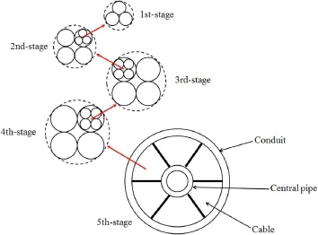
Fig.1 Cross-sectional configuration of the CICC conductor
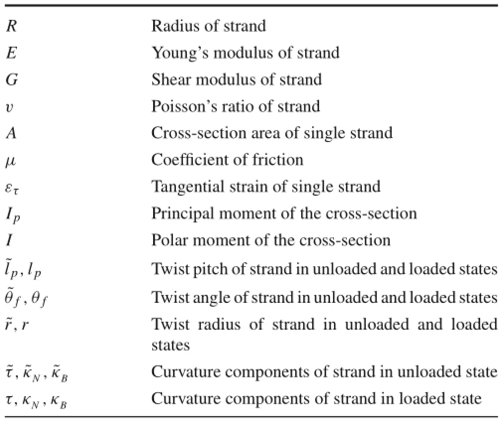
Table 1 List of symbols
2 Basic equations
2.1Geometry description and the coordinate systems
The basic structure of the CICC is shown in Fig.1[32,33],which is composed of 1152 superconducting strands with multilevel helical structure.Tables 1 and 2 present the used symbols and the parameters,respectively.The initial strain in the cooling process is ignored and the geometry described in Fig.1 is idealistic.
For the first sub-cable(triplet),three strands are twisted and form the specific helix structure.A Cartesian frame is established in the first sub-cable,as shown in Fig.2[34].In orderto discuss the mechanicalbehaviorsofa single strand,a Frenetcoordinate system is attached to the centerofthe spiral curve with unit principal normal,binormal,and tangentialvectors.The Frenet coordinates o´-τn b can be established by the following procedure:the global Cartesian coordinates rotate o-x yz around the z-axis at an angle α and then rotate about the n axis at an angle θf.Then,θfis the twist angle of the strand,and α,which lies in the x-y plane,is the angle ofrotation(see Fig.2).The transformation relationshipbetween the globalCartesian coordinatesand the localFrenet coordinates are given as follows[34]

Table 2 The parameters for CICC[8]

Fig.2 Frenet c oordinate systems o´-τn b
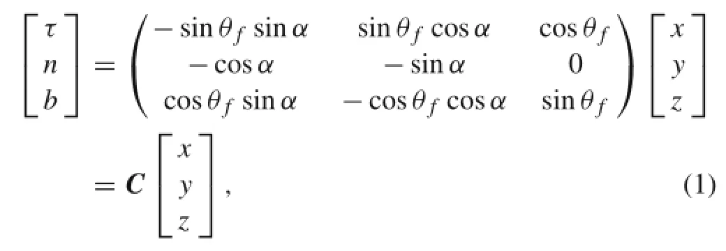
where the transformation matrix is defined as C.
2.2Equilibrium and constitutive equations
In the following analysis,each strand is considered a long and curved rod,and we make the assumption that the strand remains helical after deformation.Consider a force-loaded thin rod,as shown in Fig.3.Applying the thin rod theory to each helical strand results in the following equilibrium equations[35,36]

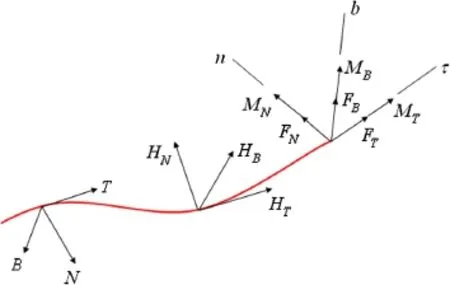
Fig.3 Loads acted on a thin rod
where FT,FN,and FBare the resultant forces acted on the strand in the tangential,normal and binormal directions,respectively.MT,MN,and MBare the moments acted on the strand in the tangential,normal and binormal directions,respectively.T,N,and B are the line loads in the tangential,normal,and binormal directions,respectively. HT,HN,and HBare external twist moments per unit length in the tangential,normal,and binormal directions,respectively.κN,κB,andτ are the components ofthe curvature and torsionalcurvature perunitlength in the loaded state,respectively.s represents the arc length.The constitutive relations of a helical rod are

where ετis the tangential strain in a single strand.˜κN,˜κB,and˜τ representthe componentsofthe curvature and torsional curvature perunitlength in the unloaded state,respectively.E is the Young’s modulus ofthe strand,A is the cross-sectional area of the strand.G Ipdenote the torsional rigidity and I is the cross-sectional moment of inertia.Thus,we have established the geometricalrelationship,the constitutive laws,and the equilibriumequations in the globaland localcoordinates,respectively.In the following sections,the analytical method is applied to calculate the strain and stress states ofthe single strand.
3 Contact force under different loads
3.1The contact force of the triplet cable under tensile strain
Consider a strand loaded with force distributed along the axial direction uniformly.For this case,we can make an assumption that the mechanical behavior in each strand is the same,and the tension,torsion,bending,and curvatures are uniform along the length of the wire.When the triplet is loaded with the axial strain εz,according to the relationship between the strain tensors[34],the strain ε´in the local coordinates are

where ε represents the strain tensor in the global coordinates.The tangential strain in a single strand can be derived as[33,37]

The relationship between theετandεzwas verified in Qin et al.[31].Furthermore,the twist angle,twist pitch,and the twistradius ofthe helicalrod should satisfy the compatibility condition

The twist angle of the strand after deformation can be obtained from Eqs.(5)and(6).By neglecting the influence due to the change of θfand contact deformation,the twist radius is expressed as a function of the tangential strain[38]

The relationship between the twist angle and twist radius for unloaded and loaded states under different tensile strains is shown in Fig.4.It can be concluded that change of twist angle and radius are negligible before and after the deformation.
Then,the components of the curvature and torsional curvature perunitlength in unloaded and loaded states are given as follows

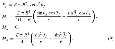
The axial force and the moments of single strand can be obtained from Eq.(3)
When a strand hasa large twistangle,itcutsperpendicular to the triplet axis and will have an irregular shape[39].Here,the strand cut is simplified into a circular shape due to the small twist angle in Table 2.Figure 5a shows that a helical strand is subjected to the distributed line contactforces g and u,and friction forces p,q,υ,and w.In addition,the othertwo strands in the tripletwillalso be in contact with contact force h.Based on the local equilibriums of force and moment,the external forces and moments along the tangential,normal,and binormal directions are given by

Fig.4 a The twist angle and b twist radius at unloaded and loaded states
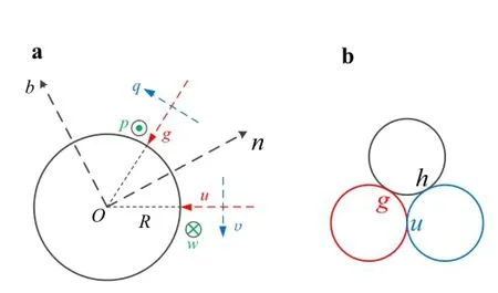
Fig.5 a Distributed load on a single strand.b Contact point for triplet

Because all the internal forces and moments in the strand do not vary with the arc length s for the tensile strain,the relationship can be written as follows

When the friction between the helical strands during the tension of the triplet is considered,friction forces acting on the surface are

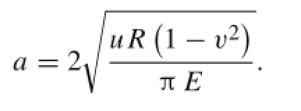
We can obtain the contact and friction forces from Eqs.(10)-(12)and(2).It is found that the contact forces of triplet are equal,u=g=h.Note that the symmetric condition is equivalent to the free-friction in normal plane.However,the irregular structure may lead to the sliding friction.Now the contact force and contact stress for the tensile strain can be determined.The expression of contact stress is given by

where the width of contact region a is[40]
The results based on previous models[26,35]are compared with the presentmodelincluding internalforce,contact force,and contactstress,as shown in Figs.6 and 7.There are some differences between the two models.This is because the strand cut is simplified into circular in the present model,while in the previous model[26],the projection of a circular cross-section on the strand cut is elliptical.Figure 6 shows the relationship between the internal forces and moments with the tensile strain.Figure 7 illustrates contact forces and stresses with the tensile strain.It is expected that the contact forces and moments will increase with the tensile strain.In addition,a large pitch length can lead to a smaller contact force and stress.Because the short twist pitch leads to entangling the strand tightly,this provides large contact forces,and tight compaction is likely to provide better strand support[41].Comparing the present model and the other model verify the results of our calculation.

Fig.6 a Internal forces under tension.b Moments under tension
3.2The contact force of the triplet under bending
For a triplet with a curvature κ in the central axis when subjected to bending,the strain in each strand can also be calculated.In Fig.8,if the axis of triplet is along the z-axis in the initial state,the strain is[42]

Forthe tangentialstrain in each strand,we apply the transformation relation of Eq.(4)

The deformed components of the curvature and torsional curvature perunitlength willbe obtained by Costello’smodel[35]


Fig.7 a Contactforcesand b contactstressasa function ofstrain with different twist pitches
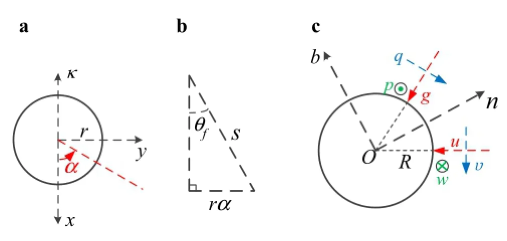
Fig.8 Geometrical relationship and loads acted on a single strand under bending.a The bending in global coordinate.b Geometrical relationships.c Loads acted on a single strand
Now,we assume thatthe twistangle and the twistradius of the helix remain unchanged afterthe deformation in Sect3.1. The changes of curvatures are

Since the deformation of a triplet under bending is complex,we will adopt a general assumption.Generally,the tangential strain ετof a single strand has two different assumptions:(1)the relative slipping between the adjacent strands and friction force are small enough(friction coefficient is small)[43].Thus,the bending load does not affect the axial strain.(2)the friction force between the strands is large enough,so there is no slipping anywhere.Then,the tangential strain of single strand is ετfor this case.
Because the true friction force isbetween the valuesoftwo assumptions,we assume that the strain on the strand in the global coordinate system retains sinusoidal distribution with the sliding friction.Although the slipping will change the strain of the strand,the distribution of strain is still periodic. Thus,the slipping only affects the magnitude of strain,while the distribution remains unchanged.The rate of change of the internal force and moment with arc length is obtained by Eqs.(3)and(17)

For a single strand,the strand balance requires the resultantforcesand momentsto be equalto zero.Now there are six equilibrium equations and four unknown parameters.Thus,itis difficultto find the results thatcan satisfy the six equilibrium equations.For simplicity,we adopt the similar method given by Gnanavel et al.[26],and use the first,fourth,fifth,and sixth equations of Eq.(2).The above distributed forces and moments along the tangential,normal,and binormal directions from Fig.8 are as follows
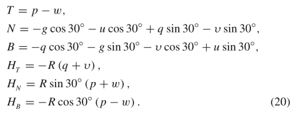
The friction force between strands is also given by Eq.(12).
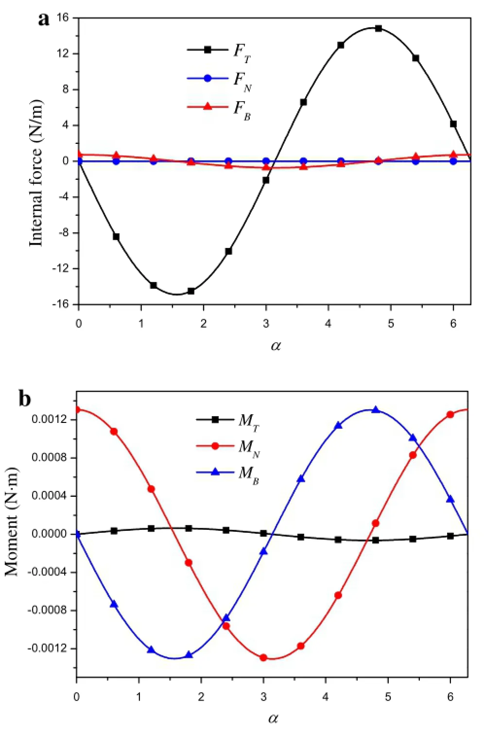
Fig.9 a Internal forces and b moments as a function of α under bending(the peak bending strain is 0.1%)
Figure 9 shows the internal force and moment with rotational angle.For the tensile loading,the magnitudes of internal force and moment are constants along the axis of the strand,while the distributions of the internal force and momentforbending are different.Itcan be found thatinternal force and momentare periodic functions ofthe bending rotational angle.This is because the strain in the cross-section of the triplet is not uniform and changes with the location of strand.Then,the strain,curvature,and torsional curvature are distributed periodically along the arc-length due to periodic helical structure.In addition,the internal force and moment are odd or even functions of rotational angle.By rearranging Eqs.(19),(20),and(2),the contact and friction forces u and g are presented in Figs.10 and 11.With u and g,the contact force h can be obtained directly.We can see that both the contact forces and contact stresses change with the rotationalangle periodically.The contactforces g,u,and h are very close,and the directions of friction forces are different.Moreover,the contactforce orstress are symmetric in one period,and decrease with the twistpitch.This is because a smaller twist pitch means more intensive strand winding,which leads to a large contact force under the same strain.

Fig.10 a Contact force and b contact stresses as a function of α under bending(the peak bending strain is 0.1%)
3.3The contact of the strand for the second-stage cable with bending
Next,we willpay attention to the second-stage cabling under bending.For the case of a second-stage cable,the triplet is assumed to be a uniform cylinder.When the second-stage cable is loaded with a bending moment,the curvature is κ,as shown in Fig.12.The overall strains of the triplet with Eq.(4)are written as follows

where the superscript p represents the triplet.

Fig.11 a Contact force g and b contact stresses as a function of α for different twist pitches
In addition,as the second-stage cable is under bending,and the triplet is also subjected to bending and torsion[44]

The global and local coordinates systems will be established in the triplet and single stand.Then,the tangential strain of single strand is obtained using the transformation Eq.(4).

where f represents the strand of triplet.
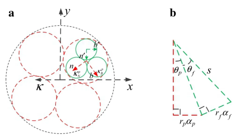
Fig.12 a The Frenet frame and b geometry relationship of single strand when the second-stage cable subjected bending strain
Thus,the changes of the curvature components and the torsional curvature per unit length of strand due to bending are

The internal force and moment can be obtained from Eq.(3),and the rotationalangle ofstrand and tripletis a function of the arc length.It can be written as follows(Fig.12)

The change rates ofinternalforce and momentwith the arc lengthcan be obtained with Eqs.(3),(24),and(25).The initial curvatures and torsional curvature per unit length of a single strand in the second-stage cable is derived by[45]

The finalcurvaturesand tensionalcurvature perunitlength are formulated as
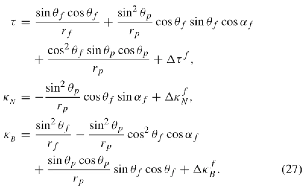
In addition,the friction force between stands can also be given by Eq.(12).
Based on the previous discussions and equations,the contact force can be determined.The variation of contact forces with rotational angle are plotted in Fig.13.Since the distributions of internal force and moment are complicated,it is found thatthe contactforce and stressare notsymmetric with respect to the rotational angle as the second-stage cable is under bending.This trend is different from that for the triplet under bending.However,the contact forces and stresses still remain periodic,and the period changes with the twist pitch ofthe second-stage cable.In addition,the forces and stresses ofdifferentcontactpoints in cross-section are also very close to each other.The contact force will reach the maximum at 4.06 or 9.86 radians in the two cycles.It is well known that contact force can affect the superconducting properties.The local position where the contact force reaches the maximum will degrade the overall properties.For the different twist pitches of a second-stage cable,there is a phase difference between the contact forces.The large twist pitch can lead to the decreasing of the contact force,which is similar to that of the triplet.
3.4Friction loss in the triplet
In order to obtain the friction loss between two strands,the two-dimensional model is adopted to take into account the localcontactcharacteristic.The contactarea is a long strip of width 2a.As shown in Fig.14,the contact area can be classified as a stick region and slip region[40].As the tangential force is less than the limiting friction force(q0<q´),there is a small relative motion in the slip region.The remainder part of the contact surface deforms without relative motion in the stick region-c≤x≤c.All points on the surface of the stick region have the same tangential displacements.

Fig.13 Contactforcesand contactstressasa function ofαf.a Contact forces.b Contact stresses under the same twist pitch 45 mm.c The contact force g for different twist pitches(the peak bending strain of second-stage cable is 0.1%)
Cattaneo[46]proposed the condition for the local sliding contact problem of the sphere,and the relative tangential displacement is also presented.Then,the frictional energy loss of the contact between two spheres is obtained in Ref.[47]on the basis of Ref.[46].Now,we use the same procedure to calculate the energy loss oftwo-dimensionalcylindercontact.The cylinderis considered a halfplane when the contact width is assumed to be much smaller than the cylinder radius.In order to consider the slip region,the contact force P is fixed and the tangential force Q is increased gradually. Then,the distributions of tangential traction on the contact surface are[40]
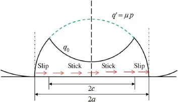
Fig.14 Contact of cylinders with parallel axes

and the displacement of the stick region δxis

In addition,the tangential displacement δxof the stick region can be written as a function of P and Q

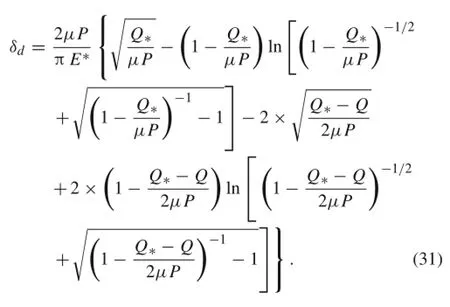
When the tangential force is increased to Q∗and begins to decrease,the tangential displacement δdduring unloading is
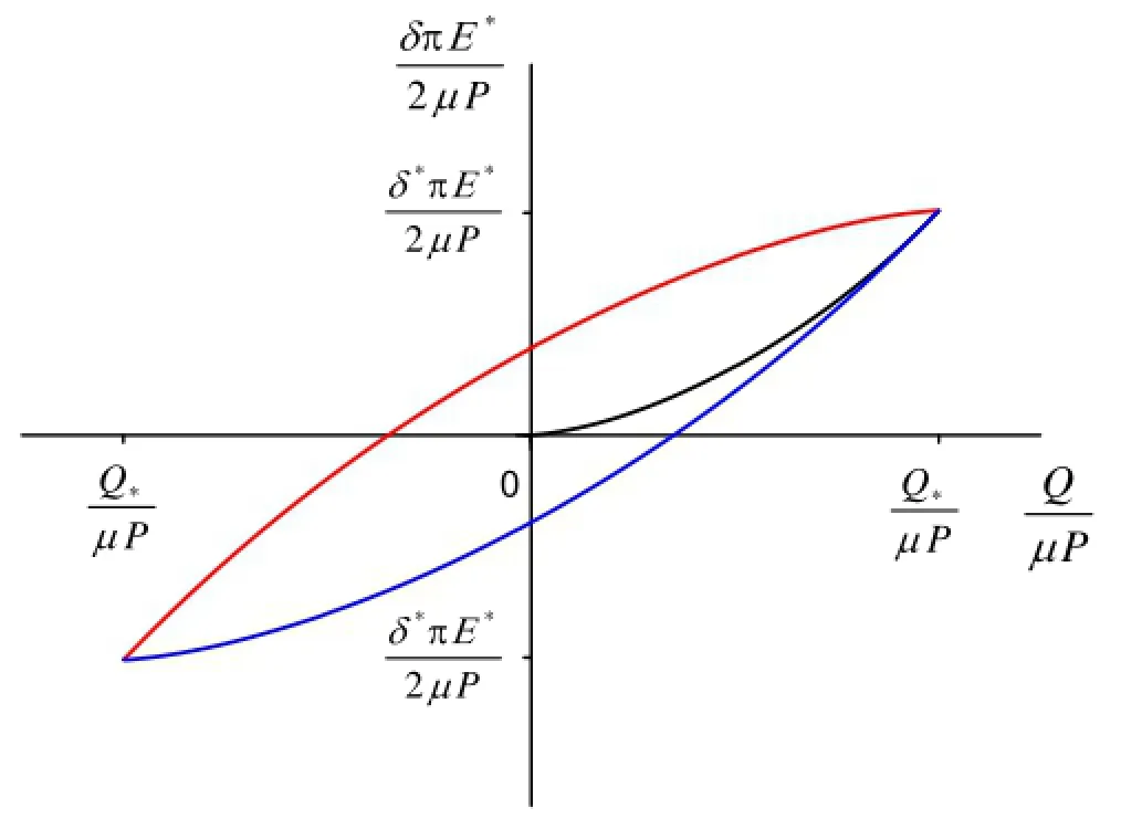
Fig.15 The displacement as the function of Q
Using the same method,the displacement δican be obtained under the reverse loading
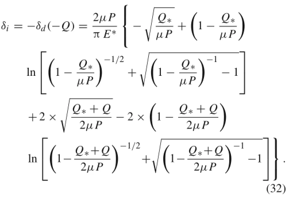
Thus,the relation between the tangential force and displacementfora cyclic loading in the stick region is presented. It is to be noted that the dissipated energy in the slip region during a cycle can be determined by the area of the loop,as shown in Fig.15,which agrees with Ref.[47].
The dissipated energy can be obtained with integration,and the expression for the energy dissipated per cycle is given by
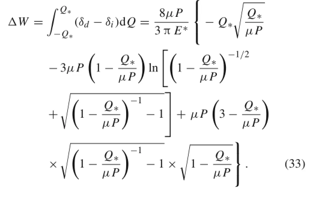
As the tangential force is equal to μP and all points will have relative slip,the energy dissipation is

4 Friction loss for different strains
Based on Eq.(34),for the triplet under tensile or bending strain,the periodic friction loss in the normal plane for one cycle is

In addition to the friction loss of normal plane,slip in the osculating plane also exists.Since the τ direction of the helicalstrand is different,there is an angleβ fortwo adjacent strandsin the triplet.The strainsforthe strandsare differentin the axialdirection ofsingle strand,and the relative slip exists between strands.For the tension case,the periodic friction loss in the osculating plane is

where q(s)is the uniform friction force between two strands,and

For the triplet under bending strain,the friction loss of normalplane is consistentwith thatofthe tensile strain,while the friction loss in the osculating plane is
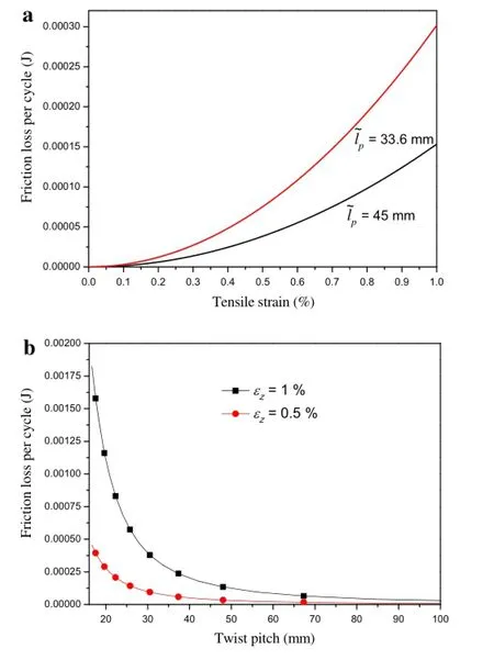
Fig.16 Friction losses as a function of strain or twist pitch under tension.a The friction losses vary with tensile strain.b The friction losses vary with twist pitches

Then,the total friction loss is

Friction loss presented by Eqs.(35)and(36)shows that it consists of two parts under tensile strain:one is proportional to the load,and the other is related to the square of the load. The form of loss is the same as Ref.[48].
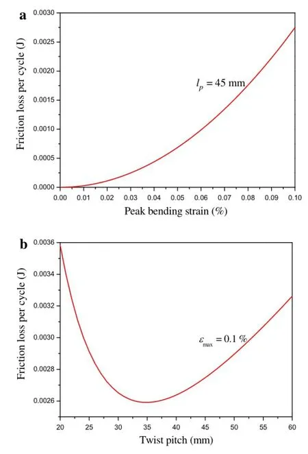
Fig.17 Friction losses as a function ofstrain ortwistpitch underbending.a The friction losseschange with peak bending strain.b Thefriction loss change with twist pitches
The total friction losses are plotted in Figs.16-18.Figure 16 shows the friction loss as the tripletisunderthe tensile strain.The value of mechanical loss has the same order as experimental results of CICCs under electromagnetic forces[49].It is expected that the friction loss increases with the tensile strain and decreases slowly with the twist pitch.This phenomenon is because the contact force decreases with the twist pitch.In Fig.17,the triplet is under the bending strain. Itis found thatfriction loss also increases with bending strain for a given twist pitch.However,the friction loss is not monotonic with the twist pitch,where lfrepresents the twist pitch of single strand.The friction loss will decrease firstly and subsequently increase with the twistpitch.The minimum value offriction loss is obtained atthe twistpitch ofabout35 mm.This result shows that a shorter twist pitch can reduce mechanical losses in a certain range.Figure 18 demonstrates the friction loss for the second-stage cable subjected to the bending strain.The friction loss for the second-stage cable under bending is smaller than that for the triplet under bending.When the peak bending strain of the second-stage cable and the twist pitch of triplet are constant,the relationship between the friction loss of the triplet and twist pitch of the second-stage cable are more complicated.As the twist pitch is very large orsmall,the friction losswilldecrease monotonically.It is interesting that as the twist pitch is between 60 mm and 80 mm,there is one local minimal loss and a local

Fig.18 Friction losses as a function of strain or twist pitches for second-stage cable under bending.a The friction losses change with peak bending strain.b The friction loss change with twist pitches
maximal loss.The loss of triplet takes the local minimum at a pitch of 65 mm.This also presents the advantage of short pitch in the local region.In summary,there is the optimal twist pitch for multi-stage structure from the point of the mechanical loss.It has been pointed out that the short twist pitch,where the strands are tightly entangled,prevents the electromagnetic force from deforming the strand[41],and offers a better strand against the Lorentz force and avoids filament fracture[4].
5 Conclusions
In this paper,a theoretical model is proposed to analyze the strain and stress states and mechanical loss of strand structures.A global and local analysis method is established,which can be applied to multistage strand structures.Firstly,the global analysis is employed to obtain the overall strain and stress of the triplet under tension or bending.Then themechanical response of each strand in the triplet can be worked out.Using the geometrical relations,the curvature and torsional curvature for unloaded and loaded states are obtained.Then,the contact force and friction force between the strands are obtained with the constitutive equations and the equilibriumequations.The axialand circumferentialfriction losses are presented using the strain relationship and the two-dimensional contact model.The results show that the short pitch length can lead to large contact stress,and the mechanical loss will decrease with the twist pitch.The contact force and mechanical loss are validated with other models.The variation of mechanical loss is associated with the geometry structure of CICC conductor.The mechanical loss increases with the bending strain.However,the relation between the mechanicallossand twistpitch is notmonotonic. The value of twist pitch is about 35 mm or 65 mm where the mechanical loss reaches the local minimum when the triplet or second-stage cable subjected to bending.
Acknowledgments The project was supported by National Natural Science Foundation of China(Grants 11202087,11472120,11421062),the NationalKey ProjectofScientific Instrumentand Equipment Development(Grant 11327802),the National Key Project of Magneto-Constrained Fusion Energy Development Program(Grant 2013GB110002),and New Century Excellent Talents in University of Ministry of Education of China(Grant NCET-13-0266).
1.Ciazynski,D.:Review of Nb3Sn conductors for ITER.Fusion Eng. Des.82,488-497(2007)
2.Shikov,A.,Nikulin,A.,Silaev,A.,et al.:Development of the superconductors for ITER magnet system.J.Nucl.Mater.258-263,1929-1934(1998)
3.Mitchell,N.,Bessette,D.,Gallix,R.,et al.:The ITER magnet system.IEEE Trans.Appl.Supercond.18,435-440(2008)
4.Devred,A.,Backbier,I.,Bessette,D.,et al.:Challenges and status of ITER conductor production.Supercond.Sci.Technol.27,044001(2014)
5.Mitchell,N.,Devred,A.,Libeyre,P.,et al.:The ITER magnets: design and construction status.IEEE Trans.Appl.Supercond.22,4200809(2012)
6.Devred,A.,Backbier,I.,Bessette,D.,et al.:Status of ITER conductordevelopmentand production.IEEETrans.Appl.Supercond. 22,4804909(2012)
7.Nijhuis,A.,Ilyin,Y.,Wessel,W.A.J.:Spatialperiodic contactstress and criticalcurrentofa Nb3Sn strand measured in TARSIS.Supercond.Sci.Technol.19,1089-1096(2006)
8.Nijhuis,A.,Ilyin,Y.:Transverse load optimization in Nb3Sn CICC design;influence of cabling,void fraction and strand stiffness. Supercond.Sci.Technol.19,945-962(2006)
9.Nijhuis,A.,Ilyin,Y.:Transverse cable stiffness and mechanical lossesassociated with load cyclesin ITERNb3Sn and NbTiCICCs. Supercond.Sci.Technol.22,055007(2009)
10.Zhu,J.Y.,Luo,W.,Zhou,Y.H.,et al.:Contact mechanical characteristics of Nb3Sn strands under transverse electromagnetic loads in the CICC cross-section.Supercond.Sci.Technol.25,403-406(2012)
11.Mitchell,N.:Assessmentofconductordegradation in the ITERCS insert coil and implications for the ITER conductors.Supercond. Sci.Technol.20,25-34(2006)
12.Jia,S.,Wang,D.,Zheng,X.:Multi-contactbehaviorsamong Nb3Sn strands associated with load cycles in a CS1 cable cross section. Phys.C Supercond.508,56-61(2015)
13.Hruska,F.H.:Calculation ofstressesin wire ropes.Wire Wire Prod. 26,766-767(1951)
14.Hruska,F.H.:Radial forces in wire ropes.Wire Wire Prod.27,459-463(1952)
15.Hruska,F.H.:Tangential forces in wire ropes.Wire Wire Prod.28,455-460(1953)
16.Love,A.E.H.:ATreatise on the MathematicalTheory ofElasticity. Dover Publications,New York(1944)
17.Costello,G.A.,Phillips,J.W.:Effective modulus of twisted wire cables.ASCE J.Eng.Mech.Div.102,171-181(1976)
18.Phillips,J.W.,Costello,G.A.:Analysisofwire ropeswith internalwire-rope cores.J.Appl.Mech.52,510-516(1985)
19.Utting,W.S.,Jones,N.:The response of wire rope strands to axial tensile loads-Part I.Experimental results and theoretical predictions.Int.J.Mech.Sci.29,605-619(1987)
20.Costello,G.A.,Phillips,J.W.:Static response ofstranded wire helical springs.Int.J.Mech.Sci.21,171-178(1979)
21.Phillips,J.W.,Costello,G.A.:General axial response of stranded wire helical springs.Int.J.Non Linear Mech.14,247-257(1979)
22.Velinsky,S.A.:General nonlinear theory for complex wire rope. Int.J.Mech.Sci.27,497-507(1985)
23.Raoof,M.,Hobbs,R.E.:Analysis of multilayered structural strands.ASCE J.Eng.Mech.Div.114,1166-1182(1988)
24.Lee,W.K.:An insightinto wire rope geometry.Int.J.Solids.Struct. 28,471-490(1991)
25.Elata,D.,Eshkenazy,R.,Weiss,M.P.:The mechanical behavior of a wire rope with an independent wire rope core.Int.J.Solids. Struct.41,1157-1172(2004)
26.Gnanavel,B.K.,Gopinath,D.,Parthasarathy,N.S.:Effect of friction on coupled contact in a twisted wire cable.J.Appl.Mech.77,293-298(2010)
27.Knapp,R.H.:Helicalwire stressesin bentcables.J.Offshore Mech. Arct.Eng.Trans.ASME 110,55-61(1988)
28.Raoof,M.:Methods for analysing large spiral strands.J.Strain Anal.Eng.Des.26,165-174(1991)
29.Papailiou,K.O.:On the bending stiffness of transmission line conductors.IEEE Trans.Power Deliv.12,1576-1588(1997)
30.Inagaki,K.,Ekh,J.,Zahrai,S.:Mechanical analysis of second order helical structure in electrical cable.Int.J.Solids.Struct.44,1657-1679(2007)
31.Qin,J.,Wu,Y.,Warnet,L.L.,et al.:A novel numerical mechanical model for the stress-strain distribution in superconducting cablein-conduit conductors.Supercond.Sci.Technol.24,1360-1363(2011)
32.Mitchell,N.:Operating strain effects in Nb3Sn cable-in-conduit conductors.Supercond.Sci.Technol.18,S396(2005)
33.Dong,S.,Jing,Z.,Yong,H.D.,et al.:A theoretical model for characterizing the internal contact of the CICC strands under axial strain.Acta Mech.Solida Sin.(in press)
34.Jing,Z.,Yong,H.,Zhou,Y.:Theoretical modeling for the effect of twisting on the properties of multifilamentary superconducting strand.IEEE Trans.Appl.Supercond.23,6000307(2013)
35.Costello,G.A.:Theory of Wire Rope.Springer,Berlin(2001)
36.Li,Y.,Yang,T.,Zhou,Y.,et al.:Spring model for mechanicalelectrical properties of CICC in cryogenic-electromagnetic environments.Cryogenics 62,14-30(2014)
37.Yong,H.,Yang,P.,Xue,C.,et al.:Fracture behavior of filament in Nb3Sn strands with crack-bridging model.Fusion Eng.Des.102,66-73(2016)
38.Zhao,Z.L.,Zhao,H.P.,Wang,J.S.,et al.:Mechanical properties of carbon nanotube ropes with hierarchical helical structures.J. Mech.Phys.Solids 71,64-83(2014)
39.Zhao,Z.-L.,Li,B.,Feng,X.-Q.:Handedness-dependenthyperelasticity of biological soft fibers with multilayered helical structures. Int.J.Non Linear Mech.81,19-29(2016)
40.Johnson,K.L.:Contact Mechanics.Cambridge University Press,Cambridge(1985)
41.Nabara,Y.,Hemmi,T.,Kajitani,H.,et al.:Impact of cable twist pitch on-degradation and AC loss in conductors for ITER central solenoids.IEEE Trans.Appl.Supercond.24,1-5(2014)
42.Timoshenko,S.:Strength of Materials.D.Van Nostrand Company Inc,New York(1930)
43.Lanteigne,J.:Theoretical estimation of the response of helically armored cablesto tension,torsion,and bending.J.Appl.Mech.52,423-432(1985)
44.Li,Y.X.,Wang,X.,Gao,Y.W.,et al.:Modeling for mechanical response of CICC by hierarchical approach and ABAQUS simulation.Fusion Eng.Des.88,2907-2917(2013)
45.Yen,J.Y.,Chen,C.H.:Theoreticalapproach to the solutions of axially loaded complex ropes.J.Chin.Inst.Eng.29,725-731(2011)
46.Cattaneo,C.:Sulcontatto didue corpielastici:distribuzione locale degli sforzi.Rend.Accad.Naz.Lincei.27,342-348(1938)
47.Mindlin,R.D.,Deresiewica,H.:Elastic spheres in contact under varying oblique forces.J.Appl.Mech.20,327-344(1953)
48.Vinogradov,O.G.,Huang,X.,Huang,X.,et al.:Extension of a cable in the presence of dry friction.Struct.Eng.Mech.4,313-329(1996)
49.Egorov,S.,Rodin,I.,Lancetov,A.,et al.:AC loss and interstrand resistancemeasurementforNbTicable-in-conduitconductor.IEEE Trans.Appl.Supercond.12,1607-1611(2002)
15 February 2016/Revised:9 May 2016/Accepted:12 May 2016/Published online:22 July 2016
©The Chinese Society of Theoretical and Applied Mechanics;Institute of Mechanics,Chinese Academy of Sciences and Springer-Verlag Berlin Heidelberg 2016
- Acta Mechanica Sinica的其它文章
- Gradient systems and mechanical systems
- A phase-field study on the oxidation behavior of Ni considering heat conduction
- Numerical study on the deformation of soil stratum and vertical wells with gas hydrate dissociation
- Reliability assessment on interfacial failure of thermal barrier coatings
- Nonlinear integral resonant controller for vibration reduction in nonlinear systems
- Numerical analysis of stress distribution in the upper arm tissues under an inflatable cuff:Implications for noninvasive blood pressure measurement

