Numerical simulation of 3-D free surface flows by overlapping MPS*
Zhen-yuan TANG (唐振远),You-lin ZHANG (张友林),De-cheng WAN (万德成)
State Key Laboratory of Ocean Engineering,School of Naval Architecture,Ocean and Civil Engineering,Shanghai Jiao Tong University,Shanghai 200240,China,E-mail:zhenyuanhome@foxmail.com
Collaborative Innovation Center for Advanced Ship and Deep-Sea Exploration,Shanghai 200240,China
An overlapping moving particle semi-implicit (MPS) method is applied for 3-D free surface flows based on our in-house particle solver MLParticle-SJTU.In this method,the coarse particles are distributed in the whole domain and the fine particles are distributed in the local region of interest at the same time.With the fine particles being generated and removed dynamically,an algorithm of generating particles based on the 3-D overlapping volume is developed.Then,a 3-D dam break flow with an obstacle is simulated to validate the overlapping MPS.The qualitative comparison among experimental data and the results obtained by the VOF and the MPS shows that the shape of the free surface obtained by the overlapping MPS is more accurate than that obtained by the UNI-coarse and close to that obtained by the UNI-fine in the overlapping domain.In addition,the water height and the impact pressure at P1are also in an overall agreement with experimental data.Finally,the CPU time required by the overlapping MPS is about half of that required by the UNI-fine.
overlapping particle,moving particle semi-implicit (MPS),generating particles,free surface flow,dam breaking
Introduction
The meshfree particle method is a flexible tool to deal with largely deformed free surface flows such as the dam breaking[1,2],the wave breaking[3,4],the sloshing[5],and the wave-body interaction[6].However,when it is applied for the 3-D free surface flows,the number of the corresponding particles with a uniform mass increases sharply,which may lead to a huge computational cost in terms of CPU time and memory requirement.To overcome this problem,some attempts were made to develop local refinement techniques.Feldman and Bonet[7]proposed a particle splitting technique,which was considered as the major step towards Adaptive Particle Refinement (APR) by Barcarolo et al.[8].Based on Feldman's work[7],Vacondio et al.[9,10]studied a coalescing technique.Similar to Feldman's work[7],Lopez et al.[11]described another particle splitting criterion by minimizing the error of the gradient of a general function.Most of these attempts were implemented based on weakly compressible SPH (WCSPH) with the explicit algorithm to produce the pressure field.Unlike the WCSPH,a semi-implicit algorithm is often adopted to obtain the pressure field in the moving particle semi-implicit(MPS),which makes it much more difficult developing the local refine technique in the MPS than that in the SPH.Recently,Shibata et al.[12]proposed an overlapping particle technique (OPT) in the MPS to reduce the computational cost.Then,Tang et al.[13]applied this overlapping method for 2-D free surface flows based on their in-house code MLParticle-SJTU.However,the capability of the overlapping MPS for 3-D free surface flows is not made evident.
The main purpose of the present work is to apply the overlapping particle technique[12]for a 3-D dam break flow with an obstacle.This paper is organized as follows:firstly,the improved MPS (IMPS) method together with the overlapping technique are introduced briefly.In particular,we employ a different pressure gradient term to be consistent with the conservative model in the IMPS.In view of the fact that the high-resolution particles are generated or removeddynamically in the overlapping region,an algorithm of generating particles in our previous work[13]is extended to the 3-D case now.Finally,the validation is made against a 3-D dam breaking flow,with the computational results compared with the experimental data in the literature.
1.Governing equations
In the MPS method,the governing equations are the mass and momentum conservation equations.They are as follows:

whereρis the fluid density,Vis the velocity vector,pis the pressure,νis the kinematic viscosity,gis the gravitational acceleration vector,andtis the flow time.
2.Particle interaction models
2.1 Kernel function
In the MPS method,the differential operators are modeled based on a kernel function.In the present work,we adopt the following modified kernel function suggested by Zhang and Wan[14],which can be expressed as follows:

wherer is the distance between particles and reis the supported radius of the particle interaction domain.
2.2 Gradient model
In the traditional MPS,the gradient operator is expressed as a weighted average of the gradient vector between particle i and its neighboring particlesj,and it can be expressed as

where n0is the initial particle number density,dis the space dimensions,andris the coordinate vector of the fluid particle.
Equation (4) suffers from a drawback that it cannot conserve the linear and angular momentums of the system.To overcome this problem,we employ a conservative form as follows[15]

2.3 Divergence model
The divergence model for the vectorV can be formulated as[15]

2.4 Laplacian model
The Laplacian operator is modeled by a weighted average of the distribution of a quantity φ from particlei to its neighboring particlesj,which can be expressed as follows:

where the parameter λ is introduced to keep the variance increase equal to the analytical solution.
2.5 Model of incompressibility
In the MPS method,the semi-implicit algorithm is adopted and the pressure fields are obtained implicitly through solving the Poisson pressure equation(PPE).In the present work,we employ a mixed source term method combined with the velocity divergence free condition and constant particle number density condition,which is proposed by Tanaka and Masunaga[15]and rewritten by Lee et al.[16]as

where ∆tis the calculation time step,the superscripts kand k +1indicate the physical quantity in the kth and (k +1)th time steps,γis the weight of the particle number density term in the right hand side of Eq.(9)and is assigned a value between 0 and 1.In this paper,γ=0.01is selected for all numerical experiments.
2.6 Detection of free surface particles
In the MPS method,the Dirichlet boundary condition is imposed by assigning zero pressure for surface particles.By now,some approaches were developed to detect the free surface particles.Tanaka and Masunaga[15]judged the surface particle by using the number of neighbor particles to overcome the misjudgment in the traditional method.Lee et al.[16]combined the above method and the small particle number density.Khayyer et al.[17]proposed a new criterion based on asymmetry of neighboring particles,in which particles are judged as the surface particles according to the summation of x -coordinate or y-coordinate of the particle distance.In the present study,we employ a detection method[14]which is also based on the asymmetry arrangement of neighboring particles,but on different equations,in order to describe the asymmetry more accurately,as follows

If the absolute value of the function F at particle i is more than a threshold α,then particleiis considered as a free surface particle,and this can be expressed as follows

where α is assigned to 0.9|F|0,and |F|0is the initial value of |F| for the surface particle.
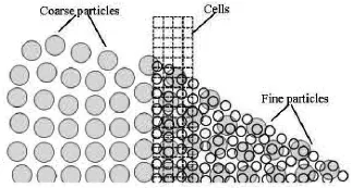
Fig.1 Concept of overlapping particle method
3.Overlapping particle technique
3.1 Outline
The OPT is a local refinement technique in the frame of the MPS,which was first proposed by Shibata et al.[12].As shown in Fig.1,the large particles(also called the coarse particles or the low-resolution particles) are distributed in the whole computation domain,while the fine particles (also called the high resolution particles or the light particles) are only distributed in the local domain of interest (or called the overlapping domain).This overlapping region is occupied by both the coarse particles and the fine particles when the fluid flows in the overlapping domain.However,the interaction between particles of different sizes is a one-way process,where only the coarse particles can influence the fine particles but not other way round.In particular,the entire flow field is first solved through the coarse particles,and then the local flow is recalculated through the fine particles together with the truncated boundary information from coarse particles.In view of the fact that no fine particles are outside the overlapping region,the imaginary cells are distributed in the truncated boundary of the overlapping domain to compensate the effect of the incomplete support domain for fine particles in these cells such as the correction of the PPE and the pressure gradient model.Furthermore,the imaginary cells can also be used to generate and remove particles.If we denote the outer layer cells as the inflow/outflow cells,each inflow/outflow cell will be checked whether it is empty at the beginning of each time step.If a target cell is vacant and is surround by coarse particles at the same time,a fine particle will be generated in the target cell and its position is determined using the inflow technique developed by Shibata et al.[6].After the motion of the particles at each time step,each particle in these cells is checked whether it is out of the range of the overlapping domain.If so,this fine particle will be removed.It should be noted that the operations of generating and removing particles are only valid for fine particles,but not for coarse particles.
3.2 Algorithm of generating and removing particles
Generating and removing fine particles dynamically plays a key role in the OPT.In the present work,an algorithm of generating and removing particles in our previous work[13]is employed here since it is similar for 2-D and 3-D cases.However,this algorithm is still introduced briefly for the completeness of this paper.As mentioned above,the fine particles are removed directly if they flow out of the overlapping region.Different from the removing particles,generating a fine particle is a complex process.It includes two main parts,that is,where to place the generated particle and how to determine whether the vacant cell is surrounded by coarse particles numerically.Since the former problem can be solved by the inflow technique[6],the key step of the algorithm is to judge whether an empty imaginary cell is surrounded by coarse particles in the 3-D.We first define a quantity χ,which is equal to the ratio of the overlapping volume Vcoverto the cell volume Vcell.Ifχis greater than a threshold χ0,it can be concluded that the cellis covered by coarse particles.Here,we assume that the particle is a cube in shape.The covered volume is also a cube in shape.Hence,the covered volume can be expressed as Vcover=lxlylz,where lx,ly,lzare the covered lengths inx,yandzdirections,respectively.
In this study,only the calculation of the covered length inx direction is discussed in what follows because the cases iny,z directions are similar.Let xcbe the center of the candidate coarse particle with the edge length2R and likewise2ris the edge length of the candidate imaginary cell.xl,xrare the left and right boundaries of the imaginary cell.Define dmax,dmin,Vl,Vras follows:
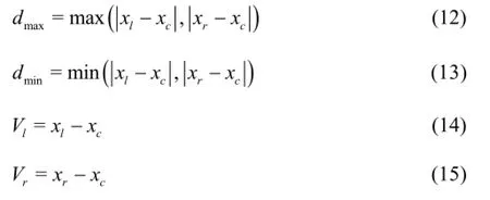
The covered volume Vcovercan be calculated as follows:ifdmin≥R,then set Vcover=0and terminate the calculation,ifVlVr≥0,the whole cell locates on the same side of the center of the candidate coarse particles,and two possible cases should be considered.If dmax>R,l=R+r-d,else l=2r,if VlVr<0,the whole cell locates on the different side of the center of the candidate coarse particles,and there are also two possible cases.Ifdmax>R,l=R+dmin,else l=2r,Calculate the covered volume Vcover=lxlylzand the cell volumeVcell.
Then,calculate the ratio χ=Vcover/Vcell.Ifχ>χ0,it can be concluded that the candidate cell is covered by coarse particles.At the same time,a fine particle can be generated in this cell if it is empty.
3.3 Modified PPE and pressure gradient model
For fine particles in the imaginary cells,their supported domain is incomplete.Therefore,the special treatments should be made for these particles.Shibata et al.[12]gave the corrected PPE and the pressure gradient model as:


where pcellis the pressure at the center of the cell where the target fine particlei locates.Note that Eq.(17) is consistent with the traditional gradient model (Eq.(4)) through replacing piwith pcell.In this study,the conservative gradient model is adopted,and the corresponding modified pressure gradient model is formulated as


Fig.2 Geometry of the dam break (m)

Fig.3 Locations of pressure probes on the box (m)
4.Test case
The dam breaking problem is often used as a benchmark for the violent flow evaluation by meshfree particle methods[1,2].In this section,a 3-D dam break flow with an obstacle is numerically simulated.
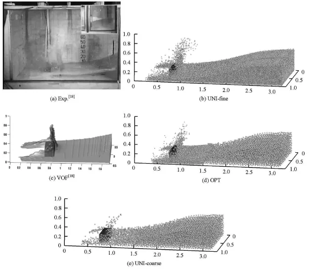
Fig.4 Comparison of snapshots of dam break flow between results of experiment,MPS and VOF,at time 0.56 s
The set-up of dam break is shown in Fig.2.A tank of 3.22 m(L)×1.00 m(B)×1.00 m(H)with an open roof is used,and the overlapping subdomain is shown as the Fig.2(b).The right part of the tank is initially filled with water of 0.55 m in depth.Att=0s,the door is suddenly opened and the water can flow freely.A small obstacle of 0.403 m×0.161 m×0.161 m is placed in the tank as shown in Fig.3.The details of the experiment can be found in Ref.[18].In the calculation,the kinematic viscosity of water isν=1.01× 10⁻⁶m2/s,the gravity acceleration isg=9.8 m/s2.
The computational parameters in all simulations are summarized in Table 1,where the prefix UNI represents that the whole domain is discretized as uniform particles and solved only by using the uniform MPS method and OPT indicates that high-resolution particles are overlapping on the heavy particles in a local region and the OPT method is employed.
Figure 4 qualitatively compares the MPS results with the experimental snapshots[18]and the VOF results[18]at the physical time t = 0.56 s .The global motion of the fluid obtained by the present MPS is quite similar with the experimental one and the VOF result.Both the MPS and the VOF reproduce the flow phenomena in terms of the liquid splashing.In addition,the shape of the free surface obtained by the UNI-fine seems more accurate than that obtained by the UNI-coarse,while the OPT can reproduce the same accurate shape of the free surface as that obtained by the UNI-fine in the vicinity of the obstacle.It is expected that the UNI-fine can give the best result.However,the result obtained by the OPT is better than that obtained by the UNI-coarse and close to that obtained by the UNI-fine in the overlapping domain.Furthermore,with the increase of the resolution,a more accurate shape of the free surface can be obtained.
The water height evolution calculated by the MPS at the location H2is illustrated in Fig.5 and compared with the experiment result[18].The general agreements between the MPS and the experiment are seen.The large peak can be observed at t=1.8sdue to the returned water from the left side wall.This peak is not obvious in the results obtained by the MPS due to the low-resolution simulations,and this can be improved by increasing the resolution[19].In addition,the flow in this moment is quite violent,involving overturned free surfaces and splashing water,and a perfect agreement is almost impossible.

Fig.5 Time histories of water heights
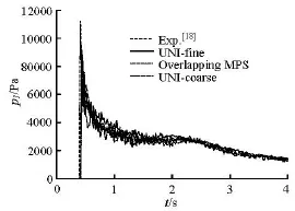
Fig.6 Impact pressure time histories at probe P1

Table 2 The pressure peak and corresponding time
The evolution of the impact pressure at the location P1(in the front of the obstacle) is illustrated in Fig.6,where the MPS results are again compared with the experiment results[18].It is seen that the overall trend of the numerical results is in agreement with the experimental one.The pressure peak and the corresponding time are also listed in Table 2 and this peak occurs when the water front reaches the obstacle.One may specially note that the peaks of the Exp.[18]and the VOF[18]are the differences between the maximum and the initial value.From this table,the instant obtained by simulations is close to that obtained by the experiment but the maximum value at the location P1is a bit underestimated.Here,the discrepancy of the impact instant is not significant among these simulations,and increasing the sample frequency may make the difference more significant.However,the maximum value obtained by the OPT is greater than that obtained by the UNI-coarse,meanwhile close to that obtained by the UNI-fine.
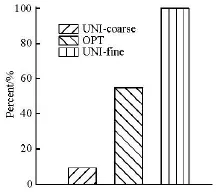
Fig.7 Comparison of required CPU time for flowing 4 s
Figure 7 shows the comparison of the required CPU time for flowing 4 s by the conventional uniform MPS and the overlapping MPS.All these cases are carried out on a personal computer of Intel i7-3770.From Fig.7,the CPU time required by the OPT is about half of that required by the UNI-fine,while both the CPU times required by the OPT and the UNI-fine are much longer than that required by the UNI-coarse.One reason is maybe that the overlapping region is large and the maximum number of fluid particles in the OPT reaches five-eighths of that in the UNI-fine and over five times of that in the UNI-coarse.
5.Conclusions
An overlapping MPS method is applied for a 3-D dam breaking flow with an obstacle.Its main idea is to distribute the low-resolution particles in the whole computation domain and the high-resolution particles in the local domain of interest.During the simulation,the flow field is first solved by the low-resolution particles,and then the local flow field of interest is recalculated by the high-resolution particles.In view of the fact that the high-resolution particles are generated or removed dynamically in the overlapping region,an algorithm to generate fine particles is developed.Then,a dam break flow with an obstacle is simulated by the uniform MPS and the overlapping MPS.The qualitative comparison among experimental data and the results obtained by the VOF and the MPS shows that the shape of the free surface obtained by the overlapping MPS is more accurate than that obtained by the UNI-coarse and close to that obtained by the UNI-fine in the overlapping domain.In addition,the water height and the impact pressure at P1 are also in an overall agreement with the experimental data.The pressure peak obtained by the OPT is close to that obtained by the UNI-fine,but greater than that obtained by the UNI-coarse.Finally,the CPU time required by the overlapping MPS is about half of that required by the UNI-fine,and this can be improved by optimizing the overlapping domain in the future work.
The present work shows that the local flow field can be refined by the overlapping technique.Nonetheless,there are still some problems,such as the mass conservation,to be resolved for a wide application of the OPT.These problems require a further study.
Acknowledgements
This work was supported by the Chang Jiang Scholars Program (Grant No.T2014099),the Program for Professor of Special Appointment (Eastern Scholar)at Shanghai Institutions of Higher Learning (Grant No.2013022),the Innovative Special Project of Numerical Tank of Ministry of Industry and Information Technology of China (Grant No.2016-23) and the Foundation of State Ley Laboratory of Ocean Engineering,Shanghai Jiao Tong University (Grant No.GKZD010065).
[1]FERRARI A.,DUMBSER M.and TORO E.et al.A new 3D parallel SPH scheme for free surface flows[J].Computers and Fluids,2009,38(6):1203-1217.
[2]ZHANG Yu-xin,WAN De-cheng.Application of MPS in 3D dam breaking flows[J].Scientia Sinica Physica,Mechanica and Astronomica,2011,41(2):140-154(in Chinese).
[3]KHAYYER A.,GOTOH H.Development of CMPS method for accurate water-surface tracking in breaking waves[J].Coastal Engineering Journal,2008,50(2):179-207.
[4]KHAYYER A.,GOTOH H.and SHAO S.D.Corrected Incompressible SPH method for accurate water-surface tracking in breaking waves[J].Coastal Engineering,2008,55(3):236-250.
[5]ZHANG Yu-xin,WAN De-cheng and TAKANORI H.Comparative study of MPS method and level-set method for sloshing flows[J].Journal of Hydrodynamics,2014,26(4):577-585.
[6]SHIBATA K.,KOSHIZUKA S.and SAKAI M.et al.Lagrangian simulations of ship-wave interactions in rough seas[J].Ocean Engineering,2012,42:13-25.
[7]FELDMAN J.,BONET J.Dynamic refinement and boundary contact forces in SPH with applications in fluid flow problems[J].International Journal for Numerical Methods in Engineering,2007,72(3):295-324.
[8]BARCAROLO D.A.,TOUZÉ D.L.and OGER G.et al.Adaptive particle refinement and derefinement applied to the smoothed particle hydrodynamics method[J].Journal of Computational Physics,2014,273:640-657.
[9]VACONDIO R.,ROGERS B.D.and STANSBY P.K.Accurate particle splitting for smoothed particle hydrodynamics in shallow water with shock capturing[J].International Journal for Numerical Methods in Fluids,2012,69(8):1377-1410.
[10]VACONDIO R.,ROGERS B.D.and STANSBY P.K.et al.Variable resolution for SPH:A dynamic particle coalescing and splitting scheme[J].Computer Methods in Applied Mechanics and Engineering,2013,256:132-148.
[11]LOPEZ Y.R.,ROOSE D.and MORFA C.R.Dynamic particle refinement in SPH:application to free surface flow and non-cohesive soil simulations[J].Computational Mechanics,2013,51(5):731-7425.
[12]SHIBATA K.,KOSHIZUKA S.and TAMAI T.Overlapping particle technique and application to green water on deck[C].International Conference on Violent Flows.Nantes,France,2012,106-111.
[13]TANG Z.,ZHANG Y.and LI H.et al.Overlapping MPS method for 2D free surface flows[C].Proceedings of the Twenty-fourth (2014) International Offshore and Polar Engineering Conference.Busan,Korea,2014,411-419.
[14]ZHANG Yu-xin,WAN De-cheng.Numerical simulation of liquid sloshing in low-filling tank by MPS[J].Chinese Journal of Hydrodynamics,2012,27(1):100-107(in Chinese).
[15]TANAKA M.,MASUNAGA T.Stabilization and smoothing of pressure in MPS method by Quasi-Compressibility[J].Journal of Computational Physics,2010,229(11):4279-4290.
[16]LEE B.H.,PARK J.C.and KIM M.H.et al.Step-by-step improvement of MPS method in simulating violent freesurface motions and impact-loads[J].Computer Methods in Applied Mechanics and Engineering,2011,200(9-12):1113-1125.
[17]KHAYYER A.,GOTOH H.and SHAO S.D.Enhanced predictions of wave impact pressure by improved incompressible SPH methods[J].Applied Ocean Research,2009,31(2):111-131.
[18]KLEEFSMAN K.M.T.,FEKKEN G.and VELDMAN A.E.P.et al.A volume of fluid based simulation method for wave impact problems[J].Journal of Computational Physics,2005,206(1):363-393.
[19]ZHANG YU-xin,TANG Zhen-yuan and WAN De-cheng.Simulation of 3D dam break flow by parallel MPS method[C].Proceedings of the 25th National Conference on Hydrodynamics and 12th National Congress on Hydrodynamics.Zhoushan,China,2013,299-305(in Chinese).
10.1016/S1001-6058(16)60632-7
(Received June 24,2015,Revised November 25,2015)
* Project supported by the National Natural Science Foundation of China (Grant Nos.51379125,51490675,11432009 and 51579145).
Biography:Zhen-yuan TANG (1988-),Male,Ph.D.Candidate
De-cheng WAN,E-mail:dcwan@sjtu.edu.cn
2016,28(2):306-312
- 水动力学研究与进展 B辑的其它文章
- Manoeuvring prediction based on CFD generated derivatives*
- Calculation of tip vortex cavitation flows around three-dimensional hydrofoils and propellers using a nonlinear k -ε turbulence model*
- Hull form optimization of a cargo ship for reduced drag*
- Numerical simulation of self-similar thermal convection from a spinning cone in anisotropic porous medium*
- An axisymmetric model for draft tube flow at partial load*
- An iterative re-weighted least-squares algorithm for the design of active absorbing wavemaker controller*

