Hull form optimization of a cargo ship for reduced drag*
Fuxin HUANG,Chi YANG
Department of Physics and Astronomy,George Mason University,Fairfax,VA 22030,USA,E-mail:fhuang@gmu.edu
Hull form optimization of a cargo ship for reduced drag*
Fuxin HUANG,Chi YANG
Department of Physics and Astronomy,George Mason University,Fairfax,VA 22030,USA,E-mail:fhuang@gmu.edu
Hydrodynamic optimization of the hull forms can be realized through the implementation and integration of computational tools that consist of a hydrodynamic module,a hull surface representation and modification module,and an optimization module.In the present paper,a new bulbous bow generation and modification technique has been developed and integrated into the hull surface representation and modification module.A radial basis function based surrogate model is developed to approximate the objective functions and reduce the computing cost.A multi-objective artificial bee colony optimization algorithm is implemented and integrated into the optimization module.To illustrate the integrated hydrodynamic optimization tools,a cargo ship is optimized for reduced drag.The optimal hull forms obtained are then validated computationally and experimentally.Validation results show that the present tools can be used efficiently and effectively in the simulation based design of the hull forms for reduced drag.
simulation based design,ship hull form optimization,drag reduction,radial basis function,surrogate model,Neumann-Michell theory
Introduction
Hydrodynamic optimization is an important aspect of ship design.Traditionally,hydrodynamic design optimization of ship hull forms is achieved using empirical method based on the accumulated hull form database.With the rapid development of computer technology,modeling methods and numerical techniques,computational fluid dynamics (CFD) based ship hull form design optimization has become more widely used in ship design.
Applications of CFD based hull form optimization for reduced calm water resistance have been reported in a significant number of studies.These studies attest to a rapidly growing interest in hydrodynamic optimization[1-23].The CFD solvers used in these studies can be classified into two categories:the low fidelity solver that is usually based on the potential flow theory with various approximations on the boundary conditions,and the high-fidelity solver that isbased on Euler/Reynolds Averaged Navier-Stokes(RANS) equations.A low-fidelity CFD solver that accounts for the dominate physics can give a reasonably accurate flow prediction with much less computing time and it is thus good for the early stage design that might require a very large number of flow evaluations.A high-fidelity CFD solver that accounts for more physics can give more accurate flow prediction with much more computing time and it is thus good for the validation of the final design.Both low-fidelity and high-fidelity CFD tools have been integrated into the hydrodynamics module of the present simulation based design tool.
In addition to the flow solver,the CFD based ship hull form design optimization requires two other components:ship hull form modification module and optimization module.In the hull form optimization process,the low-fidelity flow solver is used to evaluate the hydrodynamic performances of the ship hull forms that are generated by the ship hull form modification techniques according to the design variables updated by the optimization algorithms.
In the field of ship geometry modeling for hull form optimization,a number of techniques have been developed.These techniques can be divided into two categories:conventional modeling techniques and pa-rametric modeling techniques[9].Conventional modeling techniques build on a low level definition of the geometry,such as points.The points can be used to define curves and curves can be used to define surfaces.Therefore,these techniques offer a great flexibility to the modification of the geometry and topology.However,they require many parameters in order to conduct a fair geometry modification.These parameters will serve as design variables in the optimization process.In order to modify the ship hull form in the optimization using conventional modeling techniques,additional techniques,such as radial basis function(RBF) interpolation method[15]and modification function method[8],can be implemented to reduce the required parameters,i.e.,design variables.Parametric modeling techniques,on the other hand,build on highlevel entities.These entities are called form parameters in the geometric modeling.The most prominent advantage of parametric techniques is that small to intermediate modifications can be produced very efficiently.The parametric modeling of the hull form requires few design variables.In the present study,a RBF interpolation method is combined with a parametric modeling technique to modify the hull form locally and globally in the optimization process.
Various optimization algorithms have been used to minimize objective functions in the CFD based hull form optimization.These algorithms can be divided into two categories depending on whether the derivative of the objective function is required:the derivative based algorithms and the derivative free algorithms.Popular optimization algorithms,such as steepest descent,Newton,and conjugate gradient,are derivative based algorithms.With the help of gradient information,derivative based methods usually obtain the optimal solution efficiently.There are a number of applications on ship hull form optimization using derivative based optimization algorithms[6,23].However,the optimal solution obtained by such algorithms is a local optimum,but not necessarily the global optimum.On the other hand,derivative free optimization algorithms include the direct search methods,the evolutionary based algorithms (such as genetic algorithm and differential evolution algorithm),and the swarm intelligence based algorithms (such as particle swarm optimization algorithms,ant colony optimization algorithms,and bee colony optimization algorithms).Many of these derivative free optimization algorithms have improved the capacity of finding the global optimum.Derivative free algorithms have also been widely used in the ship hull form optimizations[12-21]due to their merits.In this study,a single objective artificial bee colony algorithm is extended to a multi-objective artificial bee colony (MOABC) algorithm to ensure the finding of the global optimums that meet several design needs at the same time.
In order to further reduce the computing time required for the CFD based hull form optimization,a radial basis function (RBF) based surrogate model is developed in this study to approximate the objective functions.Specifically,the simple (low-fidelity) CFD tool is used to evaluate the objective functions at sample points that are used to construct the RBF based surrogate model,and the MOABC algorithm is used to search for the optimal solutions using the RBF based surrogate model.
The enhancement and integration of the computational tools discussed above have enabled the simulation-based design of hull forms in terms of hydrodynamic performance.The improved integrated computational tools are used for the design optimization of a cargo ship for reduced drag in the present study.The optimal hull forms obtained are then validated computationally and experimentally.
1.Problem statement
The aim for this study is to further develop a simulation based design tool and apply it to optimize the hull form for reduced drag.In order to reduce the drag in the entire speed range,the present hull form optimization problem can be formulated as follows:

where fidefines objective function,denote the resistance obtained for the new hull form and the initial hull form,respectively,at three given design speeds that cover the low,middle and high speed,X represents the vector of design variables in ddimension defined in terms of the parameters associated with the hull form modification,and S is the feasible solution set resulting from removing the portion of the spaceRdprohibited by the constraints.In the present study,the constraint for the optimization is taken as the displacement,i.e.,the reduction of the displacement is less than one percent.

Table 1 Main particulars of the Series 60 hull (CB=0.6)
For the purpose of illustration,the Series 60 hull model is taken as an initial hull and optimized for reduced drag at three design speeds defined by Fr= 0.22,0.27 and 0.32 using the present tools.The main particulars of the Series 60 hull (CB=0.6)model are listed in Table 1 and the 3-D view of the ship hullmodel is shown in Fig.1.

Fig.1 3-D view of the original Series 60 hull model
2.Methodology
The procedure for the hull form optimization using the present simulation based design tools is described in Fig.2.
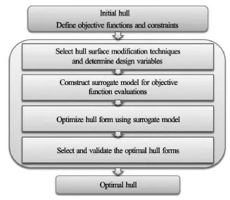
Fig.2 Flowchart of the hull form optimization procedure
It can be observed from Fig.2 that the present simulation based hull form design optimization procedure consists of four steps.After an initial hull form is selected and the optimization objective functions and constraints are defined,the first step is to select appropriate ship hull surface modification techniques and determine the design variables for the optimization problem.In order to optimize hull form for reduced drag,a steady ship flow problem needs to be solved for all hull forms generated in the optimization process at given design speeds using a CFD tool so that objective functions can be evaluated.A simple CFD tool based on linear potential flow theory can usually be used in the optimization process if the simple CFD tool is accurate enough in predicting the variations of the flow solutions due to the change of the hull forms.In order to further reduce the computing cost associated with the flow evaluations using a CFD tool,a surrogate model is developed to approximate the objective functions.Thus,the second step is to construct the surrogate model in terms of the values of the objective functions obtained using a simple CFD tool.Once the surrogate model construction is completed,it can then be used by a multi-objective optimizer during the search of the optimal hull forms in the third step.A set of optimal solutions called Pareto-front can be obtained in this step.Given a set of requirements and certain criteria,an optimal solution that defines an optimal hull form can be chosen from the Pareto-front in the fourth step.Considering the fact that the optimal hull form is obtained using a surrogate model based on a simple CFD tool,it is necessary to validate the optimal hull form in this step by a RANS/Navier-Stokes based advanced CFD tool or a model test.
The computational tools used in each step will be discussed in details in the following subsections.

Fig.3 The definition sketch of coordinate system
2.1 Drag evaluation
Consider the steady flow about a ship advancing in calm water.Non-dimensional coordinates x≡(x,y,z)≡X/Lare defined in terms of a reference length L,typically taken as the ship length.The zaxis is vertical and points upward,and the mean free surface is taken as the plane z =0.Thexaxis is chosen along the path of the ship and points toward the ship bow.The definition sketch of the coordinate system is shown in Fig.3.The Froude numberFr and the Reynolds numberRe are defined as
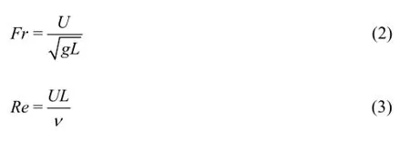
where U is ship speed,g is gravitational acceleration,andνis kinematic viscosity of the water.
The total drag of a ship hull is approximated by the summation of the wave drag and the friction drag.The wave drag is calculated by the Neumann-Michell(NM) based potential flow theory.A detailed description of the formulation and the numerical solution procedure for the NM theory can be found in authors' previous work[24-28].The friction drag is determined by an empirical formula.The total drag coefficient is defined as

whereρis the water density,U is the ship speed,Swetis the wetted surface area,RTis the total dragand CWis the wave drag coefficient evaluated by non-dimensionalizing the wave drag RWusing a conventional way as

and CFis the frictional drag coefficient evaluated using ITTC 1957 Model-Ship Correlation Line as follows

The simple CFD tool (computer code SSF) is developed based on the NM theory and the ITTC 1957 Model-Ship Correlation Line.This simple CFD tool has been used to evaluate the wave drag and the total drag for various monohull forms and catamarans.Numerical results predicted by this simple CFD tool are in fairly good agreement with experimental measurements[24-28,30,31].Therefore,the simple CFD tool,SSF,is employed to evaluate the total drag of the ship hull form in constructing the surrogate model.
2.2 Design variable selection and ship hull surface modification method
In the present study,the Series 60 hull model is considered for the hull form optimization for reduced drag.Two hull modification steps are employed to generate new hull forms in the optimization process.The first one is to generate and modify a bulbous bow using radial basis function interpolation method,the second one is to modify the entire hull body using a shifting method based on the modifications of the sectional area curve of the hull.
A radial basis function (RBF) based interpolation method can be used to deform the shape of the geometry.It has been used to generate candidate geometries in the shape optimization,such as ship hull form optimization[15,17-18].A detailed description of the method can be found in authors' previous work[15].
In order to modify the hull form,two types of control points (fixed and movable) are employed in the RBF based interpolation method.These control points can be defined either on or off the hull surface.The fixed control points are used to keep the hull surface near them unchanged.The movable control points are used as design variables to modify the ship hull surface in the shape optimization process.Their positions are determined by a given optimization algorithm to minimize the objective functions.
In the present study,the surface modification technique based on RBF interpolation method is used in the first step for the bulbous bow generation and modification.Specifically,an initial bulbous bow is generated first from the initial hull using the geometry modification tool developed in the present study.The size of the bulbous bow is then optimized in terms of the hydrodynamic performance,i.e.,the minimization of the total drag,in the present study.The top figure in Fig.4 depicts a new initial hull with a bulbous bow generated from the Series 60 hull model,and the bottom figure in Fig.4 depicts the new initial hull and a definition sketch for design variables (black dot) used in the bulbous bow optimization.Specifically,the shape of the bulbous bow is modified through three design variables,i.e.,the movable control point (black dot) can be repositioned along lateral,longitudinal,and vertical directions.

Fig.4 Fixed (a) and movable (b) control points (design variables) of the radial basis function interpolation method for the modification of the ship hull with the initial bulbous bow
The shifting method is adopted to modify the entire ship hull body in the second step.In the shifting method,the longitudinal position of sections is shifted to modify the prismatic coefficient,the longitudinal center of buoyancy,and the parallel mid-body of the initial hull.In the CFD-based hull form optimization,the sectional area curve of the initial hull form is modified during the optimization process.The new hull form is obtained by moving the stations of the initial hull form along the longitudinal direction.The amount of the movement is determined by comparing the modified sectional area curve and the original one.When the hull surface is defined by a discrete triangulation,the new hull surface can be obtained by moving the nodes of the triangular meshes according to the movement defined at given stations.
The sectional area curve can be described in various ways,e.g.,spline polynomials.In the present study,the following formulation has been used to describe the sectional area curve:

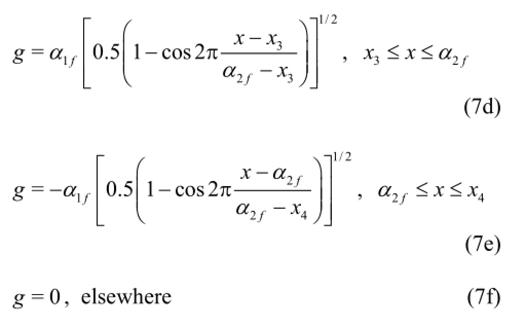
where fn(x)denotes the new sectional area curve,fo(x)the initial sectional area curve,g( x,α1a,α2a,α1f,α2f) theshape function,α1a,α2a,α1fand α2fthe parameters determined during the optimization,x1and x4are the end positions of the deformable afterbody and fore-body,respectively,x2and x3are the end positions of fixed middle body.The slopes of the sectional area curve at the fore-body and after-body are defined by the parameters α1fand α1a,respectively,and the locations of the fixed station at the forebody and after-body are controlled by the parameter α2aand α2f,respectively.By changing parameters α1f,α2f,α1aand α2a,various sectional area curves can be obtained,and the new hull forms can be produced accordingly from the initial hull form by the shifting method.A demonstration figure of the shifting method is shown in Fig.5.The advantages of this modification method are explained and illustrated by Kim et al.[15].

Fig.5 Shape function (a) and the sectional area curves (b)
By combing two surface modification methods,there are seven design variables in total used in the present study.The definition and range of these design variables as well as the modification methods associated with each design variable are defined in Table 2.
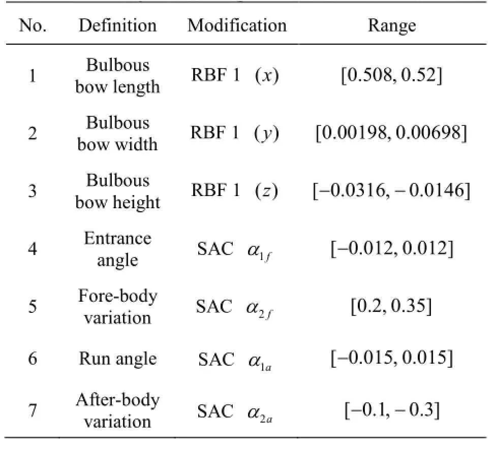
Table 2 Summary of the design variables
2.3 Surrogate model construction
To further accelerate the optimization process,a radial basis function based surrogate model is developed to approximate the objective functions during the optimization process.The details of the RBF based surrogate model can be found in authors' previous work[19].Four main steps are required to build a surrogate model in the ship hull form optimization for reduced drag.Figure 6 shows the flowchart of these steps.

Fig.6 Flowchart of the RBF surrogate model construction
The design of experiments (DOE) is a strategy for selecting sample points in the design space that aim at maximizing the amount of information acquired.In the present study,the Latin hypercube sampling (LHS)technique[32]is adopted to allocate 70 data points in the design space.Once the sample points in the design space are generated,the candidate hull forms can be produced using the surface modification tool.The total resistance can then be evaluated for these hull forms atthree given design speeds using the simple CFD tool SSF to construct three RBF based surrogate models.
After the RBF based surrogate model is constructed,the cross validation is performed to examine the accuracy of the model.The basic idea of the cross validation is to leave out one sample point,and then predict it using the model constructed by the remaining sample points.The difference between the exact value of the objective function at the given sample point evaluated by the CFD tool and the approximate value of the objective function at the given sample point predicted by the RBF based surrogate model constructed with other sample points is calculated.If the difference is small enough,the model is valid.Otherwise,increase the number of sampling points,and repeat the steps shown in Fig.6.In addition to the evaluation of three objective functions for each sample hull form generated,the displacement of each sample hull form is also calculated and recorded.Therefore,a total of four RBF based surrogate models are constructed to predict the resistance at three design speeds and the displacement of the hull forms generated in the optimization process.The cross validations for these models are performed and the results are shown in Fig.7.It can be observed from Fig.7 that the estimated objective function values (fE) given by the surrogate model show a good agreement with the exact objective function values (fC) calculated by the CFD tool directly or calculated in terms of the hull geometry directly.
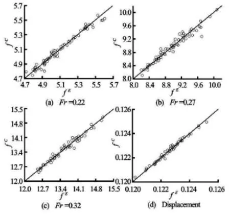
Fig.7 Cross validations of the surrogate models about three objective functions (a-c) and the constraint (d)
2.4 Multi-objective artificial bee colony optimizer
The artificial bee colony (ABC) optimization algorithm is based on the intelligent foraging behavior of the honey bee swarm and was proposed by Karaboga[33]to solve single objective optimization problems.The details of the algorithm can be found in the references[33,34].Compared with other population based optimization algorithms,one of the advantages of the ABC algorithm is that it requires only a few parameters:population size,i.e.,the bee colony size(CS),the maximum number of iterations (maxCycle),and the maximum number of trials for the bees (limit).
In the present study,a multi-objective artificial bee colony (MOABC) algorithm is developed based on the single objective ABC algorithm proposed by Huang et al.[34]by introducing the dominated solution conception and an external archive for storing nondominated solutions.As a result,the present MOABC algorithm only requires one more parameter in comparison with the single-objective ABC algorithm.This new parameter defines the external archive size (AS),i.e.,the maximum number of non-dominated solutions during the iterations.
Numerical experiments are conducted for the optimization of typical benchmark functions using the MOABC optimizer developed in this study.The results show that CS =100,maxCycle=100,limit=100 and AS=100are the appropriate choices and therefore such settings are used in the present study.
3.Results and analysis
3.1 Optimization results
The design optimization of the Series 60 hull model for reduced drag at three given speeds is carried out on a desktop PC (OpenSuse 12.1,CPU:Intel R Xeon(R) X5260 @3.33G Hz,Memory:24GB).After the RBF based surrogate model is constructed,it takes less than 10 s to obtain the optimal solutions using the MOABC optimizer.The computing time for the entire optimization that includes the construction of the RBF based surrogate model is about 40 min on the PC with above configurations.
The optimal solution set,i.e.,Pareto-front,obtained by the MOABC optimizer for three objective functions defined in Eq.(1b),is plotted in Fig.8 with empty squares.It can be observed from Fig.8 that the relationships between objective functions f1~f2,and f1~f3show a strong trade-off in the Paretofront.This implies that the hull form with the minimum resistance at lower speeds does not have minimum resistance at higher speeds.The hull form with the minimum resistance at higher speeds does not have the minimum resistance at lower speeds either.It can also be seen from Fig.8 that the relationship between objective functionsf2~f3is almost linear.Therefore,a special attention is required when designers select optimal designs from the solution of the Pareto-front.For example,the optimal solution denoted as Case 3 in Fig.8 represents an optimal hull formthat has a 2%,8%,and 9% reduction of the drag at three design speeds,respectively,with respect to the original hull.Two other hull forms,denoted as Case 1 and Case 2 in Fig.8,are so chosen that the hull form in Case 1 has the largest drag reduction at the high speed and the hull form in Case 2 has the largest drag reduction at the low speed.The value of the objective functions for the original Series 60 hull model should be zero according to the definition given in Eq.(1b),which is denoted as Case 0 in Fig.8.

Fig.8 The Pareto-front in the objective function space
In order to compare the drag reduction,three optimal hulls and the original hull,denoted as Cases 1-3 and Case 0 in Fig.8,respectively,are evaluated using simple CFD tool SSF.The relative changes of the displacement(V),wetted surface area (Swet),and the total resistanceof each optimal hull at given design speeds with respect to the original hull is listed in Table 3.It can be observed from Table 3 that the maximum reduction of the displacement of the optimal hull with respect to the original hull is 0.76%,which is consistent with the constraint that the relative reduction of the displacement should be less than 1%.
Table 3 Relative changes of the displacement (V),wetted surface area(Swet),and the total resistance at given design speedsof each optimal h ull with respect to the original hull

Table 3 Relative changes of the displacement (V),wetted surface area(Swet),and the total resistance at given design speedsof each optimal h ull with respect to the original hull
Case / V % wet/ S % 1/ T R % 2/ T R % 3/ T R % 1 -0.76 0.70 0.92 -14.21 -13.48 2 0.98 1.77 -2.07 3.95 -1.02 3 -0.02 1.02 -1.41 -8.84 -9.14

Fig.9 Comparisons of the total drag among the original hull(Case 0) and three optimal hulls (Case 1-Case 3)
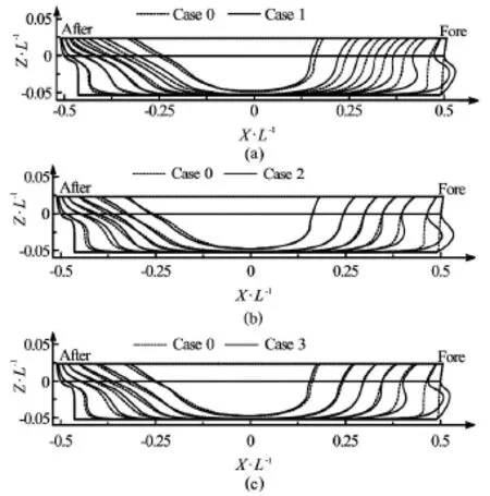
Fig.10 Comparisons of the profiles between the original hull(Case 0) and three optimal hulls (Case 1-Case 3)
In order to examine the performance of the chosen optimal hull forms at off design speeds,the total drag of the optimal hull forms are evaluated by the simple CFD tool SSF for a range of speeds.The comparisons of the total drag between the original hull and the optimal hulls are plotted in Fig.9.It can be observed from Fig.9 that the hull form in Case 3 results in a reduction of the drag in the entire speed range,while the hull forms in Case 1 and Case 2 provide maximum reduction of the drag at high speeds and low speeds,respectively.
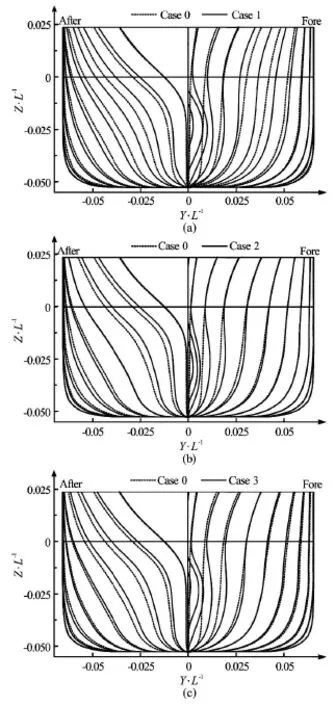
Fig.11 Comparisons of the body plans between the original hull(Case 0) and three optimal hulls (Case 1-Case 3)
The comparisons of the profiles between the original hull (Case 0) and three optimal hulls (Case 1-Case 3) are plotted in Fig.10,respectively.The comparisons of the body plans between the original hull(Case 0) and three optimal hulls (Case 1-Case 3) are plotted in Fig.11,respectively.The comparison of the sectional area curves (SAC) from the original hull and three optimal hulls are plotted in Fig.12.As shown in Figs.10-11,a large modification of the entire hull form can be observed in all three optimal hulls.This is consistent with the fact that both local and global hull surface modifications are allowed in this study.It can also be observed that the fairness and the practical manufacturability are well preserved for the optimal hull forms obtained,which demonstrates that the present hull form modification technique is very effective.

Fig.12 Comparisons of the sectional area curves from the original hull (Case 0) and three optimal hulls (Case 1-Case 3)
It should be noted that the shape of the optimal hull forms,i.e.,the size of the bulbous bow,the longitudinal distribution of the displacement,depends on the definition of the objective function,i.e.,the design speeds.The hull form with a fat bulbous bow shows the better drag reduction at the high speed (Case 1),but worse performance at the low speed,vice versa(Case 2).Narrow sectional shapes of the after-body are obtained in Case 1,while a wider sectional shape is obtained in Case 2.Finally,a combination of the modification of the Case 1 and Case 2 can be observed in Case 3,which results in a moderate reduction of the drag in the entire design speed range.
3.2 Validation of the optimal hulls using a highfidelity CFD tool
The present simulation-based design of the optimal hull forms is based on the simple (low-fidelity)CFD tool for the evaluation of the objective functions that define the hydrodynamic performance of the hulls.Therefore,it is necessary to validate the hydrodynamic performance of the optimal hull forms obtained using a high-fidelity CFD tool.In the present study,a high-fidelity open source CFD solver,called Open FOAM (www.openfoam.com),is used to evaluate the total drag of the original hull and the optimal hull obtained from Case 1 that has the largest drag reduction at high speeds.Open FOAM has been validated in authors' work for the prediction of the total drag of a ship advancing in calm water at a constantspeed[35].
According to the prediction results from the Open FOAM,the relative drag of the optimal hull form obtained in Case 1 with respect to the original hull is reduced by 8.07% at Fr =0.27and by 14.5% at Fr =0.32and increased by 3.8% at Fr=0.22The trend predicted by the high fidelity solver is consistent with the results obtained from the simple CFD tool based optimization tools.
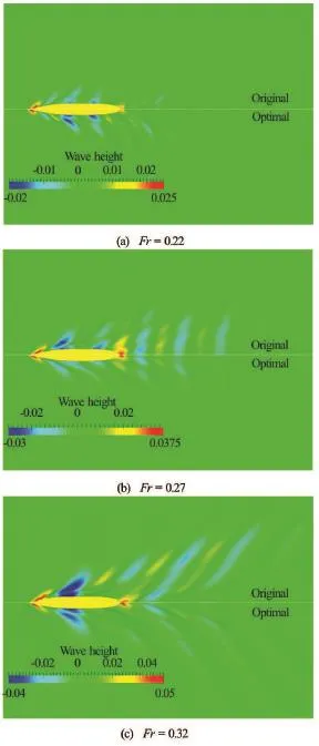
Fig.13 Comparison of wave patterns between the original hull and the optimal hull obtained from Case 1 at three speeds
The comparison of the wave patterns between the original hull and the optimal hull obtained in Case 1 at three speeds is shown in Fig.13.It can be seen from Fig.13 that the waves generated by the optimal hull form at high speeds (Fr=0.27 and 0.32) are smaller than these by the original hull form.The waves generated by the original hull form and the optimal hull form obtained in Case 1 at the low speed (F r=0.22)are comparable,which implies that there is very small change in the wave resistance between these two hulls.So the increase of the total resistance at the low speed is mainly from the friction resistance due to the increase of the wetted surface area.The results of wave pattern comparison are consistent with these of wave resistance predictions.
3.3 Validation of the optimal hulls by model tests
In order to validate the optimal hull forms obtained,a series of model tests were conducted at Wuhan University of Technology.The initial hull model and the optimal hull model obtained for the best performance at the high speed (Case 1) were built and tested in the towing tank that is 102 m long,10.5 m wide,and 2 m deep for a series of speeds ranging from Fr=0.18 to 0.34.Figure 14 shows the original hull model and the optimal hull model used in the model tests.

Fig.14 The optimal hull model (a) and the original hull model(b) used in the model tests
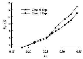
Fig.15 Comparison of the total resistance obtained from the experimental measurements for the original hull model and the optimized hull model from Case 1
The comparison of the total resistance obtained from the experimental measurements for two models is plotted in Fig.15.It can be observed from Fig.15 that the optimal hull model obtained from Case 1 has better performance at high speeds but worse performance at low speeds,which is consistent with the results from the initial numerical predictions and the late validations with the high-fidelity CFD tool.Specifically,the total resistance of the optimal hull obtained from Case 1 is increased by 5.93% at Fr=0.22with respect to the original hull,while the total resistance of theoptimal hull obtained from Case 1 is reduced by 6.42% and 13.10% at speeds Fr=0.27 and 0.32 with respect to the original hull.
4.Conclusions
A simulation based design tool is further developed and enhanced in this study and applied to the design optimization of a cargo ship for reduced drag.This design process employs two simple ship hull surface modification methods to modify the hull form locally and globally during the optimization process.The NM-theory based simple CFD tool is used for the drag (objective function) evaluation and for the construction of a RBF based surrogate model to approximate the objective functions.A newly developed MOABC optimizer is used together with RBF based surrogate model to determine the optimal designs very efficiently.A set of optimal designs,i.e.,optimal hulls,are obtained and analyzed.For the purpose of validation,a high-fidelity solver is used to evaluate the performance of the optimal hull forms obtained.The model tests are conducted to validate the performance of the optimal hull forms as well.
The comparison of the numerical results and experimental measurements show that the present optimization tools can produce superior hull forms with reduced drag.This study also demonstrates that the present multi-objective optimization tools can be used in the simulation based design of hull forms for reduced drag in the preliminary and early stage design due to its simplicity and efficiency.
Acknowledgements
This work was sponsored by the Office of Naval Research (ONR).Ms.Kelly Cooper is the technical monitor.The authors would also like to thank Dr.Baiwei Feng and Dr.Haichao Chang for conducting the model tests sponsored by the National Natural Science Foundation of China (Grant Nos.51279147,51179143 and 51479150) and providing the experimental data for the validation.
[1]PERCIVAL S.,HENDRIX D.and NOBLESSE F.Hydrodynamic optimization of ship hull forms[J].Applied Ocean Research,2001,23(6):337-355.
[2]HINO T.Shape optimization of practical ship hull forms using navier-stokes analysis[C].Proceedings of the 7th International Conference on Numerical Ship Hydrodynamics.Nantes,France,1999.
[3]PERI D.,ROSSETTI M.and CAMPANA E.Design optimization of ship hulls via CFD techniques[J].Journal of Ship Research,2001,45(2):140-149.
[4]YANG C.,SOTO O.and LOHNER R.et al. Hydrodynamic optimization of a trimaran[J].Ship Technology Research,2002,49(2):70-92.
[5]PERI D.,CAMPANA E.Multidisciplinary design optimization of a naval surface combatant[J].Journal of Ship Research,2003,47(1):1-12.
[6]CHEN P.,HUANG C.H.An inverse hull design problem in optimizing the desired wake of ship[J].Journal of ship Research,2002,46(2):138-147.
[7]TAHARA Y.,STERN F.and HIMENO Y.Computational fluid dynamics-Based optimization of a surface combatant[J].Journal of ship Research,2004,48(4):273-287.
[8]SAHA G.K.,SUZUKI K.and KAI H.Hydrodynamic optimization of ship hull forms in shallow water[J].Journal of Marine Science and Technology,2004,9(2):51-62.
[9]HARRIES S.,ABT C.and HOCHKIRCH K.Modeling meets simulation-process integration to improve design[C].Honorary Colloquium for Prof.Hagen,Prof.Schluter and Prof.Thiel.Duisburg,Germany:University of Duisburg-Essen,2004 .
[10]TAHARA Y.,TOHYAMA S.and KATSUI T.CFD based multi-objective optimization method for ship design[J].International Journal for numerical methods in fluids,2006,52(5):499-527.
[11]CAMPANA E.F.,PERI D.and TAHARA Y.et al.Shape optimization in ship hydrodynamics using computational fluid dynamics[J].Computer Methods in Applied Mechanics and Engineering,2006,196(1):634-651.
[12]ZALEK S.F.,PARSONS M.G.and BECK R.F.Evolutionary multicriterion optimization for propulsion and seakeeping[C].26th ONR Symposium on Naval Hydrodynamics.Rome Italy,2006.
[13]KIM H.Y.,YANG C.and LÖHNER R.et al.A practical hydrodynamic optimization tool for the design of a monohull ship[C].The 18th International Offshore and Polar Engineering Conference.Vancouver,Canada,2008.
[14]KIM H.,YANG C.and KIM H.Y.et al.Hydrodynamic optimization of a modern container ship using variable fidelity models[C].The Nineteenth International Offshore and Polar Engineering Conference.Osaka,Japan,2009.
[15]KIM Hyunyu1 Y.,YANG Chi.A new surface modification approach for CFD-based hull form optimization[J].Journal of Hydrodynamics,2010,22(5Suppl.):520-525.
[16]KIM H.Y.,YANG C.Hydrodynamic optimization of multihull ships[C].Proceedings of the FAST2011.Honolulu,Hawaii,USA,2011.
[17]KIM H.Y.,YANG C.Design optimization of bulbous bow and stern end bulb for reduced drag[C].The Twenty third International Offshore and Polar Engineering Conference.Anchorage,Alaska,USA,2013.
[18]HUANG F.,KIM H.Y.and YANG C.A new method of ship bulbous bow generation and modification[C].The Twenty-fourth International Offshore and Polar Engineering Conference.Busan Korea,2014.
[19]HUANG F.,WANG L.and YANG C.Hull form optimization for reduced drag and improved seakeeping using a surrogate based method[C].The Twenty-fifth International Offshore and Polar Engineering Conference.Kona,Big Island,Hawaii,USA,2015.
[20]HUANG F.,WANG L.and YANG C.et al.Hull form optimization of a TriSWACH for reduced drag[C].Proceedings of the FAST2015.Washington DC,USA,2015.
[21]WANG L.,HUANG F.and YANG C.et al.Hydrodynamic optimization of a wedge hull[C].Proceedings of the FAST2015.Washington DC,USA,2015.
[22]HAN S.,LEE Y.S.and CHOI Y.B.Hydrodynamic hull form optimization using parametric models[J].Journal of Marine Science and Technology,2012,17(1):1-17.
[23]PARK J.-H.,CHOI J.E.and CHUN H.H.Hull-form optimization of KSUEZMAX to enhance resistance performance[J].International Journal of Naval Architecture and Ocean Engineering,2015,7(1):100-114.
[24]YANG C.,KIM H.Y.and NOBLESSE F.A practical method for evaluating steady flow about a ship[C].Proceedings of the FAST2007.Shanghai,China,2007,118-126.
[25]NOBLESSE F.,HUANG F.and YANG C.The Neumann-Michell theory of ship waves[J].Journal of Engineering Mathematics,2013,79(1):51-71.
[26]YANG Chi,HUANG Fuxin and NOBLESSE Francis.Practical evaluation of the drag of a ship for design and optimization[J].Journal of Hydrodynamics,2013 25(5):645-654.
[27]HUANG F.,YANG C.and NOBLESSE F.Numerical implementation and validation of the Neumann-Michell theory of ship waves[J].European Journal of Mechanics-B/Fluids,2013,42:47-68.
[28]NOBLESSE F.,HUANG F.and YANG C.Evaluation of ship waves at the free surface and removal of short waves[J].European Journal of Mechanics-B/Fluids,2013,38:22-37.
[29]ZHANG C.,HE J.and ZHU Y.et al.Stationary phase and numerical evaluation of far-field and near-field ship waves[J].European Journal of Mechanics-B/Fluids,2015,52:28-37.
[30]HUANG F.,LI X.and NOBLESSE F.et al.Illustrative applications of the Neumann-Michell theory of ship waves[C].28th Workshop on Water Waves and Floating Bodies.L'Isle sur la Sorgue,France,2013.
[31]YANG Chi,HUANG Fuxin and KIM Hyunyul.Hydrodynamic optimization of a TriSWACH[J].Journal of Hydrodynamics,2015,26(6):856-864.
[32]MCKAY M.,CONOVER W.and BECKMAN R.A comparison of three methods for selecting values of input variables in the analysis of output from a computer code[J].Technometrics,1979,21(2):239-245.
[33]KARABOGA D.An idea based on honey bee swarm for numerical optimization[R].Vol.200.Technical report tr06,Kayseri,Turkey:Erciyes university,2005.
[34]HUANG F.,WANG L.and YANG C.A new improved artificial bee colony algorithm for ship hull form optimization[J].Engineering Optimization,2016,48(4):672-686.
[35]YANG Chi,HUANG Fuxin and WANG Lijue et al.Numerical simulations of highly nonlinear steady and unsteady free surface flows[J].Journal of Hydrodynamics,2011,23(6):683-696.
10.1016/S1001-6058(16)60619-4
(Received February 25,2016,Revised April 19,2016)
* Biography:Fuxin HUANG,Male,Ph.D.,
Research Assistant Professor
Chi YANG,E-mail:cyang@gmu.edu
2016,28(2):173-183
- 水动力学研究与进展 B辑的其它文章
- Manoeuvring prediction based on CFD generated derivatives*
- Effects of water flow on the uptake of phosphorus by sediments:An experimental investigation*
- Improved formulas for thermal behavior of oscillating nanobubbles*
- Lattice Boltzmann method for Casimir invariant of two-dimensional turbulence*
- The experiment and analysis of transitional flow in pipe*
- Numerical simulation of 3-D free surface flows by overlapping MPS*

