Computational study of different venturi and orifice type hydrodynamic cavitating devices*
Kuldeep,Virendra Kumar SAHARAN
Chemical Engineering Department,Malaviya National Institute of Technology,Jaipur-302017,India,E-mail:kuldeeproy123@gmail.com
Computational study of different venturi and orifice type hydrodynamic cavitating devices*
Kuldeep,Virendra Kumar SAHARAN
Chemical Engineering Department,Malaviya National Institute of Technology,Jaipur-302017,India,E-mail:kuldeeproy123@gmail.com
(Received July 11,2015,Revised September 12,2015)
This paper reports optimization of various geometrical parameters of two types of hydrodynamic cavitation reactors (HC)such as venturi type and orifice type.Mostly orifice and venturi nozzles are used as HC reactor,a simple valve can also be used to cause cavitation which depends on geometry and area of opening.Different operating and geometrical parameters such as divergence angle,throat height/diameter to length ratio,number of holes and inlet pressure to the cavitating device were selected to study the inception,growth and dynamics of cavities.In this work,a comprehensive computational fluid dynamics simulation is performed to numerically investigate the 3-D flow behaviors within HC reactors using cavitational model with standard k-εTurbulence model.The study of different geometries of venturi type HC reactor (like slit,circular and elliptical) shows that 1:1 of the ratio of throat height/diameter to length and 6.5oof divergence angle is an optimum geometry for best cavitational activity.In case of orifice,1:3 of the ratio of diameter to length is best for cavitation and an increase in the total flow area increases the cavitational yield.
hydrodynamic cavitation (HC),computational fluid dynamics (CFD),cavitation number (CN),venture,orifice
Introduction
In general,cavitation is a fluid mechanics phenomenon which is the formation of cavities in the medium due to pressure fluctuation.Fluctuating pressure field significantly causes damage,erosion on the surface and generation of shock waves.Cavitation was first explained by Lord Rayleigh in 1917,and he analyzed the behavior of spherical bubbles near a marine impeller[1].He concluded that the gaseous bubbles near impeller get affected by fluctuating pressure field.In low pressure region,the generated bubbles grow in size and tend to shrink when the pressure is recovered.In shrinking,bubble wall velocity start increasing and the inertia of liquid become higher than bubble and hence bubble collapses adiabatically in that condition.This collapse generates the shock wave which causes erosion of impeller.Therefore,cavita-tion can reduce the performance of hydraulic equipments like impellers,turbines valves,pump and turbo machinery parts etc.[2].
Over the past few years,many scientists have carried out their researches on cavitation to raise the process yield by utilizing large amount of energy which is released at the time of collapse in different fields of engineering applications[3-10].In hydrodynamic cavitation (HC),cavities are generated in flowing medium using mechanical constriction/geometries like orifice,venturi and valves.When liquid passes through these constrictions,the pressure at throat falls below vapour pressure of liquid and thus rapid formation of vaporous cavities takes place with dissolved gases and suspended solids present in the flowing medium.After generation,cavity undergoes expansion and compression phases.Bubble wall velocity decreases in isothermal expansion phase and increases in compression phase or collapse phase according to conservation of momentum.These implosions of collapse release large amount of energy,generating localized “hot spot” with drastic increase in temperature and pressure (temperature in the order of thousand kelvin and pressure in the order of thousand atm)[5].Under these conditions,water molecules are thermallydissociated into OHand Hfree radicals.These OHfree radicals are then diffused into bulk liquid medium where they oxidize the organic pollutants.These free radicals intensify the chemical reaction or may prompt the chemical reaction at ambient condition which is otherwise not possible and may require high temperature and pressure conditions[6].In some cases,cavity collapse may break the large molecular weight compound into smaller ones and it can occur at different locations of the reactor simultaneously.This makes cavitation an alternative option in various engineering applications.Cavitation also generates local turbulence and liquid micro circulation at the time of collapse which enhances the transportation rates (mass,momentum and heat) and thereby increasing the reaction rate[1].These effects are responsible for process intensification and have varied applications in various processes such as microbial cell disruption[3],sonochemistry[4],water and effluent treatment[6-8],leaching[11],enzyme recovery[12],crystallization[13],medical applications[14]and emulsification[15-17]etc..
Therefore,many researchers have been doing their research on dynamics of cavitation to develop the flow elements such as orifices,valves and venturies which are capable of generating cavities.These types of constrictions are placed in a pipe carrying a stream of fluid which increases the stream kinetic energy at the throat[1].Throttling in such devices should be sufficient to keep the pressure below the vapour pressure of flowing medium to generate cavities.A venturi has advantage over the orifice due to its smooth converging and diverging sections but orifice can generate high velocity at throat for a given pressure drop and it can accommodate more number of holes in a given cross sectional area and also it is easy to fabricate[18].In addition,the high speed and high pressure homogenizers also generate cavitating conditions[19].In view of the industrial application as well as for obtaining efficient design of cavitational reactors,it is very crucial to understand the physics behind the actual phenomenon of cavitation occurring inside the cavitational reactor[19].
Saharan et al.[9]have studied different types of cavitating devices like circular venturi,slit venturi and single hole orifice plate for degradation of waste water pollutant (orange-G).They have concluded that the efficiency of HC depends on geometries of cavitating reactor (open flow area,the ratio of throat height/ diameter to length and divergence section) and operating conditions (initial concentration,pH,cavitation number (CN) and inlet pressure).The cavitational intensity depends on cavity collapse which is controlled by operating conditions.
Sivakumar and Pandit[10]have also studied different multiple holes orifice for the degradation of waste water pollutant (Rhodamine B).They observed that modification of flow geometries and hence turbulent pressure fluctuation frequency (fT)could enhance the cavitational intensity.The orifice plate with more number of hole openings i.e.,having smaller hole size achieve a larger area of the shear layer as compared to the same flow area of larger hole size and because of that the value of fTincreases,which leads to a more cavity formation and intense collapse of generated cavities.Hence,the ratio of perimeter to open area of throat(α)becomes the deterministic parameter for cavity density in a cavitation reactor.
Bashir et al.[20]have optimized important geometrical parameter of cavitating venturi using computational fluid dynamics (CFD).Optimization of different type of venturies was done in terms of cavity inception,cavity growth (throat height to length ratios) and pressure recovery rate (divergence angle).
Badve et al.[19]have modeled and simulated a different type of hydrodynamics cavitational reactor comprising of a stator and rotor assembly to predict the flow patterns by describing the shear rate and pressure variation in the complex flow field.Using high accuracy simulation schemes and Navier-Stokes equation,fluid properties were investigated.They have concluded that higher rotational speeds of the rotor,tends to stabilize the flow,which in turn results in less cavitational activity compared to that observed around 2 200 rpm-2 500 rpm.
In the present study,various designs of the cavitating reactor such as slit venturi,circular venturi,elliptical venturi,single hole orifice and multiple holes orifice by varying different operating and geometrical parameters were studied to observe the cavitating conditions.CFD (ANSYS Fluent 14.5) methodology was used to observe the hydrodynamic behavior inside a cavitator and different cavitating reactors were optimized.Hence,this work employs an idea in the design of optimized cavitating reactors for getting maximum cavitational effect of a HC reactor.
1.An approach in the design of cavitating reactors
The approach followed in this paper is based on the assessment of selected simulation problems which are considered to be typical and represents the cavitation applications.Here,two types of modified cavitational reactor (venturi and orifice) are used to optimize various geometries and different operating conditions.Different flow areas of throats such as venturi type (slit,circular and elliptical) and orifice type(single hole and five holes) are considered for optimization.A venturi has high pressure recovery and low pressure loss due to minimal flow separation but on the other hand,an orifice has limited pressure recovery and medium pressure loss which generate substantial flow separation.Both venturi and orifice have an upstream section,a throat and a downstream sectionbut gives different pressure recovery rates for same pressure drop.Generated cavity collapse is a result of pressure recovery from the lowest pressure detected at vena-contracta of HC reactors.At the time of pressure recovery,the fluid stream gets separated and hence eddies are generated.The change in momentum of the flow caused by contraction in flow area generates turbulence by eddy motion which enables the permanent pressure loss.As by Bernoulli's principle,reduction in flowing cross-sectional area of stream increases the velocity head which is conserved at the expense of pressure head.Orifice and venturi nozzles are generally used as HC reactor.
The cavitation in liquid medium contains four stages,cavity inception,growth,rapid collapse and rebound.The cavity inception (nucleation) occurs when local pressure falls below the vapour pressure of liquid.The metastable state of liquid can be achieved by stretching below its saturated vapour pressure where thermodynamic change takes place from liquid to vapour.Thus,liquid moves towards more stable state which has low free energy[1].The growth of bubble occurs when bubble pressure is greater than the local pressure but in case of shrinking/collapse,bubble pressure becomes less than the local pressure.In rebound stage,some bubbles are not fully collapsed then bubble re-grows in size and collapse.Apart from this phenomenon,cavity can breakup or coalesce depending on the level of interaction between bulk liquid and cavities.Moholkar et al.[21]have observed that with increase in the flow area of HC reactors,the shear layer area also increases and so does the cavitational intensity.This cavitational intensity increases with the ratio(α),which is defined as

Mikic et al.[22]have given the classical theory of bubble growth.They found a suitable approximation for the radius of a growing bubble which link together heat diffusion controlled growth given by Plesset and Zwick and inertia driven bubble growth given by Rayleigh's model.The temperature difference between surrounding liquid and the bubble decrease the bubble growth.Its residence time in low pressure region is the deciding factor for cavity growth to gain sufficient energy before it collapse.A smaller residence time will not permit the bubble to grow to its required size and a longer time will lead the cavity to coalesce with other cavities which decrease the cavitational yield.Thus,in this study,the ratio of throat height/diameter to length was varied from 1:1 to 1:3 to see the growth rate.
The dynamics of bubble collapse is very complex to explain.Florschuetz and Chao[23]analyzed the dynamics of bubble collapse in the form of bubble collapse criteria (Beff)which is the ratio of collapse time of inertia controlled to the collapse time of heat diffusion controlled phenomena.When the ratio is more than 10 (approximately),the collapse is primarily driven by the pressure difference between surrounding liquid and cavity which is inertia controlling step.This controlling step defines the initial stage of bubble collapse.The total time of bubble collapse is:

where Rois initial radius of the bubble,pvis vapour pressure of liquid and ρlis density of liquid.
When bubble collapse criteria (Beff)is less than 0.5 (approximately),then heat controlled step will appear.This temperature difference reduces the growth of bubble and collapse leads to rebound which occurs due to decay in oscillation of cavity radius by surface tension and viscous effects.Except for the bubble collapse,the inside temperature of cavity is assumed to be uniform (isothermal condition)[1].In the literature,Rayleigh and Plesset have given the bubble dynamic equation by assuming spherical bubble in inviscid and incompressible liquid.
When a cavity grows to a required size,its residence time should be optimal in the low pressure zone i.e.,at the throat before collapse.In case of venturi type HC reactor,the rate of pressure recovery is controlled by divergence angle but in the case of orifice type HC reactor,the intensity of bubble collapse is observed in downstream section.The rate of pressure recovery should not be too high which will result in the boundary layer separation in divergence section and subsequently loss in final recovered pressure.Thus,the angle of divergence region is an essential parameter for analysis of cavitation zone in venturi type HC reactors.The divergence angle ranges from 5oto 15ofor a standard non cavitating venturi.The effect of divergence angle is an important parameter in order to avoid boundary layer separation due to high pressure recovery rate for non cavitating venturi reactor.But for cavitating venturi reactor,the pressure recovery rate should be favorable.Therefore,in this study half divergence angle ranging from 5.5oto 7.5o(the divergence angle of a standard non-cavitating venturi type HC reactor ranging from 11oto 15o) was chosen for optimization.
In orifice type HC reactors,boundary layer separation occurs near inlet hole.In low pressure region,due to drastic change in flow direction and cross sectional area,boundary layer tends to separate from the inlet throat of the wall known as vena-contracta.Subsequently,recirculation zone appears near inlet hole wall between vena-contracta and hole wall.In this work,the total flow area has been increased with an increase in number of hole to analyze the cavitational yield.
2.Mathematical modelling
2.1 Conservation equation
The Navier-Stokes equation is used as the initial stage of the analysis for axisymmertic,incompressible,viscous fluid in flowing device.Eulerian multiphase model approach is applied to derive the transport equation (Navier-Stokes equation) by solving mass,momentum and energy conservation equations.Kunz et al.[24]and Carrica et al.[25]studied the numerical approach for the simulation of multiphase flow.A separate set of conservation equation is applied for each phase.
Mass conservation equation

where vkis the velocity of phasek,Γkdrepresents the interfacial mass exchange between phaseskand lwherek denotes liquid and v denotes vapour,αkis the vapour volume fraction (VVF) of phase k and the balance equation which refer to the total vapor volume is

Momentum conservation equation

where τkis the viscous shear stressis the Reynold stress.Mklrepresents the interfacial momentum exchange between phaseskandl .Pressure is assumed to be identical for all phases,

2.2 Turbulence model
A turbulence model is a computational procedure in the system of flow equation so that wide variety of flow problems can be solved adopting the numerical method.It is essential to define cavitation phenomena at the time of collapse.For the momentum exchange,the implosion of bubbles is considered as the source of the production of turbulence.The k-εis applied as turbulence model which consists of turbulence kinetic energy and turbulence dissipation energy solved by Eulerian multiphase approach for each phase.
Turbulence Kinetic equation

where Pkis the production term

Turbulence dissipation equation
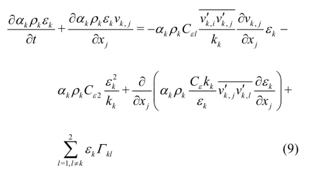
In Eq.(7) and Eq.(9),Cµ,σk,Cε1,Cε2,Cεare the closure coefficients.
3.Computational modelling
CFD can be used as an effective tool to analyze the flow behavior and cavity dynamics inside the cavitating devices at different operating and geometrical parameters.Cavitational models incorporate vapour and liquid phases and simulate it using mixture model with Fluent 14.5.It involves cavity dynamics,standard governing equations and mixture turbulence model which describe the flow and effect of turbulence.Singhal et al.[26]proposed cavitational model of two phase system with equal velocity and equal temperature at interface which is referred to as a “full cavitational model”.This proposed cavitational model was first furnished in commercial CFD package in Fluent 6.2.In this study,temperature effects are not essentialfor cavity dynamics which comes under inertia controlled regime.It considers the cavity dynamics and presence of non-condensable gases.Singhal et al.[26]used standard k-εturbulent model for analysis using constant density for both liquid and vapour phase and validated with Nurick's correlation[27].They considered the effect of turbulence in cavitation by adding an estimate of turbulent pressure fluctuation to the saturation pressure for calculating the threshold pressure of the phase change.They have stated that saturation pressure of the fluid can be elevated by fluctuations which are not correct thermodynamically.The estimation of turbulent pressure fluctuations was obtained by assuming turbulence is isotropic but in reality it is not.However,they assumed isotropic behavior for modelling.
The vapour transport equation in terms of vapour mass fraction(f)is given by:

where ρmis the mixture density,f is the Vapour mass fraction,γis the effective exchange coefficient and vvis the vapour phase velocity.Reand Rcare the vapour generation and condensation rates (or phase change rates) respectively.Here,relative velocity can be approximated to have same magnitude of characteristic turbulent velocity which is defined as square root of turbulent kinetic energy
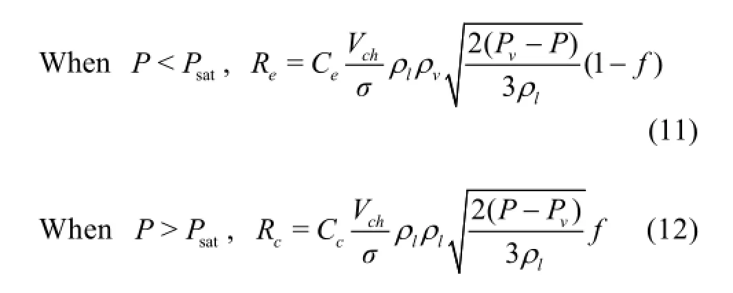
where Vchis the Characteristic turbulent velocity,σ is the surface tension coefficient of liquid phase,Pvis vapour pressure and Psatis saturated vapour pressure of liquid,Ceand Ccare 0.02 and 0.01 respectively.In the turbulence effect of cavitation,the turbulent pressure fluctuation is estimated by calculating threshold pressure phase change which is obtained by

The turbulent pressure fluctuation is obtained by assuming isotropic turbulence.Here,is calculated by

Singhal et al.[26]have limitations in few areas of application in model formulation.In the analysis of cavity dynamics of bubbles,Weber number criterion is introduced with zero relative velocity approximation which limits the cavity size.

where σ is the surface tension,ρis the density of liquid andv′is the local turbulence velocity which is given by

wherek is the turbulent kinetic energy.
4.Numerical modeling and simulation
The modeling of cavitating devices such as orifice and venturi require the knowledge of dynamics of bubbles growth and collapse.The dynamics of spherically symmetric bubble in an infinite domain of liquid with uniform temperature is introduced in Rayleigh-Plesset equation[1].It was assumed that during growth and collapse phase,bubble remains spherical and stable.Different cavity dynamics models developed in literature are based on the concept of interpenetrating continua.This employs the concept of average volume fraction of phases present at a spatial-time location in the flow.Mostly,cavitation models assume dynamic and thermal equilibrium between vapour and liquid phases.Apart from this,commercial CFD tool is used to present the effect of cavitation in cavitating devices.ANSYS Fluent 14.5 is used as a commercial CFD simulation solver.
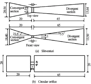
Fig.1 Schematic diagram of hydrodynamics cavitational reactors

Table 1 Geometrical detail for various cavitational reactors

Table 2 CN for different inlet gauge pressures at optimized conditions (for venturi type HC reactors:Throat height/diameter to length ratio is 1:1 and half divergence angle is 5.5oand orifice type HC reactors throat diameter to length ratio is
In this work,two types of HC reactor are optimized and their geometrical details are shown in Fig.1 and Table 1.All types of HC reactors are simulated in 3-D space to observe the flow domain,and then flow domains were cut in 2-D space along the axis of the geometries for analysis.The mesh size of HC reactor is a very essential factor in optimization.Fine meshing was done near the throat and coarse meshing near the inlet and outlet boundaries as there is no pressure gradient.In meshing,hexahedral cells were generated in HC reactors which is up to 2×10⁵cells.Steady state multiphase cavitation enabled with no slip velocity near the wall was considered for analysis.Phases,liquid and vapour are considered to be incompressible.In the mixture model,the liquid is considered to be an interpenetrating continuum.
The solution of governing equation can be found for a given geometrical configurations and specified boundary conditions.In selection of boundary condition for specified boundaries,cavitational number plays an important role because it depends on throat velocity,vapour pressure and downstream pressure.Initially,at inlet,VVF was taken to be zero as there was no cavity.However,5ppm of dissolved gas fraction was mentioned which is generally present in water.In model solving density,momentum and vapour are discretized using First Order Upwind discretization scheme and turbulent kinetic energy and turbulent dissipation rate are discretized using Second Order Upwind discretization scheme.The governing equations such as the mass conservation and the momentum balance equation were solved using the semiimplicit method for pressure linked equations-consistent (SIMPLEC) algorithm and in turbulence model standard -kεwas used.
5.Result and discussion
5.1 Influence of inlet pressure and cavity dynamics
The quantitative understanding of cavitating flow is very crucial.The variation of throat velocity and the discharge coefficient with pressure difference across the HC reactors are widely discussed in experimental studies[9,28].The formation of number of cavities and hence cavitational intensity mainly depends on pressure difference across the HC reactor and CN.The pressure fluctuation near the throat causes the cavity inception.The rate of pressure recovery is a deciding parameter of cavity dynamics.In this study,the effect of inlet pressure was analyzed for 2 atm to 10 atm with fixed outlet absolute pressure at 1 atm.
The characterization of cavity inception and degree of cavitation of HC reactors in liquid medium is defined by dimensionless number called CN[1].The CN is defined as

where P2is the fully recovered downstream pressure,Pvis the vapour pressure of the liquid and v0is the velocity at throat of cavitational reactor.In a particular flow condition,cavitation was found to occur at some particular value ofCvcalled cavitation inception number denoted by Cvi.Further reduction in Cvlower than Cviwill increase the number of the cavity[1].

Fig.2 Pressure contour at different inlet pressures in elliptical venturi
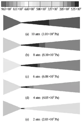
Fig.3 Pressure contour at different inlet pressures in slit venturi
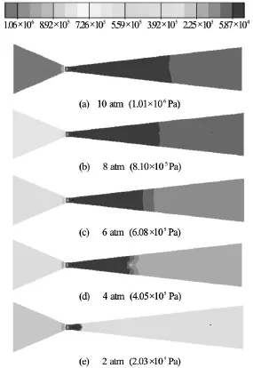
Fig.4 Pressure contour at different inlet pressures in circular venture
Inan ideal condition,CN should be less than or equal to one for cavity generation in low pressure region.But cavities can also be generated at CN greater than one due to presence of dissolved gases and suspended particles which acts as pre nuclei.At lower CN,higher cavitational activity is obtained i.e.,higher number density of cavities.But very low value of CN may results in the coalescence leading to cavity cloud that will reduce the cavity collapse intensity or collapse pressure and thus it is advisable to operate the cavitating device at a CN higher than choked conditions[5].According to Saharan et al.[9]the optimum CN ranges from 0.15 to 0.25 for the wastewater treatment application.The optimum CN in our case is obtained in the range of 0.10 to 0.20 for best cavitational activity for all the studied cavitating devices.Table 2 shows the variation of CN at different inlet pressures.The CN is generally influenced by the velocity at the throat which varies with pressure difference across reactor.Higher pressure difference across the reactor provides lower value of CN.The maximum cavitational zone is obtained at optimum inlet pressure for the respective cavitating devices.Figures 2-6 show the effect of inlet pressure for different cavitational reactor.It was observed that for elliptical venturi,theexistence of higher effective zone is achieved at pressure of 8 atm.It is a known phenomenon that higher pressure causes more rapid bubble collapse because of higher turbulence stresses.For a fixed geometry,the existence of an optimal inlet pressure value comes from two aspects:increase in number of cavities at higher pressure and higher cavitational zone.Similarly,Figs.3 and 4 shows higher cavitational zones at 10 atm inlet pressure due to more active cavities generation for circular and slit venturi.In case of orifice HC reactors,cavitational events are seen at the inlet of hole and these cavities are further extended down to the length of throat.In orifice plate cavities are grown at the periphery of the throat only whereas in the case of venturies the entire throat and part of the divergence section is filled with lot of cavities and thus venturies are proved to give higher throughput in terms of final collapse pressure generated than orifice plate.Incorporation of multiple holes orifice plate results in higher magnitude of generated pressures and cavitational intensities due to the more number of cavities are being formed because of increase in the perimeter to area ratio as compared to single hole orifice plate (Figs.5,6).The cavitational intensities depend on the flow area offered and the perimeter of holes on the orifice plate (Figs.5,6).In our study,an optimum inlet pressure as 8 atm gives maximum cavitational zone for elliptical venturi and 10 atm for circular and slit venturi.Such observations are well in accordance with experimental study found in literature[6,9,10,21].
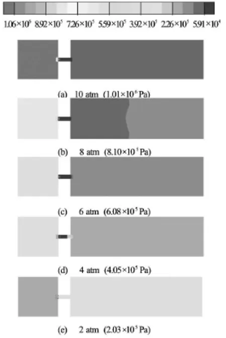
Fig.5 Pressure contours at different inlet pressures in single hole orifice
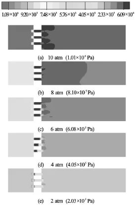
Fig.6 Pressure contours at different inlet pressures in multiple hole orifice
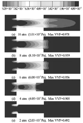
Fig.7 Comparison of maximum VVF contours at different inlet gauge pressures in single hole orifice
The cavity formation increases at higher inlet pressure.Among all the generated cavities,very few reached intense collapse (pressure more than1 000 atm and temperature more than 1 000 K) in the flow domain.Due to weak volumetric oscillation,several cavities undergo only partial collapse.Similarly,Fig.7 compared the max VVF contour for single hole orifice at different inlet gauge pressures.The maximum concentration of vapour fraction is obtained at 10 atm (max VVF=0.987)as compared to 2 atm(max VVF=0.492)due to more number of cavities which increases collapsing event and hence final collapse pressure increases.
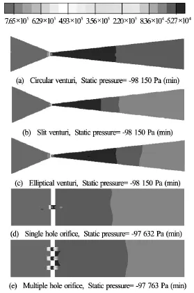
Fig.8 Static pressures of different type of HC rectors at 8 atm
5.2 Optimization of throat height/diameter to length ratio
This parameter is the deterministic parameter in deciding the maximum size of cavity which can be attained before its collapse.Smooth convergence section in venturi type HC reactor provide maximum vapour fraction at throat but sudden contraction of geometry in orifice type HC reactor is not satisfactory.After nucleation the residence time in low pressure region of cavities is affirmatory for growth and pressure recovery zone.Longer residence time in low pressure region allow cavities to grow to such an extent that it can give active cavitational collapse and several cavities might coalesce or breakup depending on the level of interaction with other cavities near their vicinity[20].Due to suspended solids and dissolved gases,there is massive chance for cavity to coalesce with other cavities,substantially in longer length of throat.However,in this study there is limitation of numerical modelling for considering the coalescing of cavities.Schmidt and Corradini[28]observed that the residence time of cavities in nozzles might be in the order of micro-seconds.And they studied the growth of cavity radius from 1.5 micron to 30 micron (approximately) in one microsecond at 106Pa pressure difference across nozzle.
Under cavitational condition,static pressure(total pressure-dynamic pressure) become negative as seen in modeling of single phase incompressible flow study in injectors by Schmidt and Corradini[28].Due to tension in liquid at low pressure region (negative pressure),liquid cannot subsist at equilibrium and get converted to the vapour and that vapour filled region have static pressure equal to corresponding saturation pressure If the tension overcomes the forces which dispute the bubble growth (surface tension and static pressure),the nucleation will start in the water.This means small bubbles,present in water grows in those areas and water will also convert to vapour resulting in a rapid growth of voids.By enabling the cavitational model,Fig.8 shows the negative static pressure contour for different HC reactors at 8 atm inlet gauge pressure.
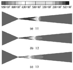
Fig.9 Density contours of slit venturi for various throat height to length ratios at optimized pressure (10 atm)
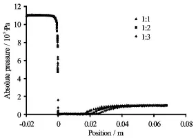
Fig.10 Pressure profiles of slit venturi for various throatheights to length ratio at optimized pressure (10 atm)

Table 3 CN for different throat height/diameter to length ratios at optimized conditions (for elliptical venturi at 6 atm,slit venturi at 10 atm,circular venturi at 8 atm and both orifice HC reactors at 8 atm inlet gauge pressure)
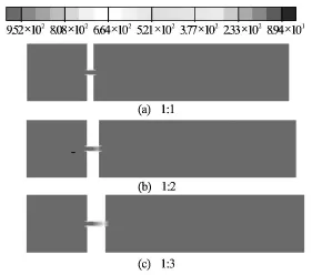
Fig.11 Density contours of circular orifice for various ratio of diameter to length at optimized pressure (8 atm)
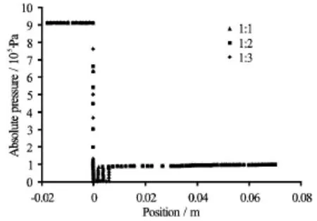
Fig.12 Pressure profiles of circular orifice for various ratio of diameter to length at optimized pressure (8 atm)
The simulations were carried out for different ratios of throat height/diameter to length,1:1,1:2 and 1:3 for each reactor to compare cavitational efficacy.The collapse intensity of cavitational zone was shown by density contour (Fig.9) for various ratios of throat height/diameter to length in slit venturi.From density contour and pressure profile along the length of venturi (Fig.10),it can be observed that the length of cavitational zone which relate to minimum pressure region or the vaporous cavities in a flowing fluid through the cavitating device is higher for 1:1 and the similar trends were also observed in the case of other two venturies.Table 3 summarizes that with an increase in length of the throat,the CN is almost remains constant for all the venturi,thus indicating that the higher length is not having any effect on the number of cavities being generated and their growth rate.On the other hand the perimeter and cross sectional area of throat/hole is affecting the number of cavities being generated.And the growth of these generated cavities is majorly affected by the pressure recovery rate in the downstream section.It may happen that the larger throat length may cause a permanent pressure drop which will not allow the cavities to experience oscillation behavior of the surrounding pressure field as in the case of smooth divergence angle and thus these cavities will no longer remain as active cavities and will dissolve in the surrounding liquid medium thereby causing a reduction in the length of active cavitation zone as evident by Figs.9 and 10.On contrary the effect of throat length was evident in the case of orifice as higher throat length will lead to the higher number of cavities being generated due to lower pressure in this region (Figs.11 and 12).Since in the venturi the numbers of cavities are very much higher than the orifice plate and thus this effect was nullified.
In this study,it has been observed that the throat diameter/height to length ration does not have any effect on the number of cavities that are generated and on its growth rate in the case of venturi and a ratio of 1:1 gives the optimal effect.whereas this parameter have a marginal effect on the orifice type of HC where higher ratio can generates more number of cavities due to the static pressure equals to the vapour pressure of the flowing fluid in the throat region.But again a very high ratio may lead to permanent pressure drop and that may turn the generated cavities into the inactive cavities.
5.3 Optimization of pressure recovery rate
After attaining the required size,the cavities collapse when they enters higher pressure region and whose effect can be observed in downstream section.This rapid collapse of cavities undergoes the adiabatic condition.Mahulkar[2]studied the cavity collapse criteria which are decided by the final condition of bubble collapse based on Vander Wall's equation.This equation gives the relationship between internal pressures due to attraction force among molecules,volume vacant for free motion of molecules,excluded volume and material volume per mole of gas.Therefore,the gas bubbles cannot compress beyond collapse volume (Product of excluded volume and material volume per mole of gas).The rate of diffusion from gas to liquid and liquid to gas is slower as compared to the time of expansion or collapse phase and vapour pressure of liquid is also limited as compared to surrounding pressure.During expansion,the pressure inside the bubble drops till its vapour pressure while in compression phase cavity vapour will condense till its compression.In compression phase,bubble wall velocity increases due to which mass transfer and heat transfer become negligible.The vapour inside the cavity gets closed with surrounding liquid and it undergoes adiabatic compression.At that condition,cavity gets collapsed and generates larger amount of energy.
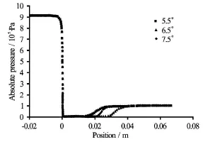
Fig.14 Pressure profiles of elliptical venturi for various divergence angles at optimized pressure (6 atm) and optimized throat height/diameter to length ratio (1:1)
In venturi type of HC reactors,the pressure recovery rate is controlled by divergence angle.Three different half divergence angles 5.5o,6.5oand 7.5owere simulated by taking rest of the parameters like inlet pressure (8 atm for elliptical venturi) and throat height/diameter to length ratio as 1:1.Density contour(Fig.13) shows cavitational effect in terms of extended length of lower density region which can be related to the presence of cavitation bubble.With an increase in divergence angle,the pressure recovers immediately after the throat which causes sudden collapse of the cavities.But for the small divergence angle pressure recovery will be smooth and cavities will grow and reach to the maximum size before they collapses resulting result in the higher cavitational intensities.This fact is also manifested in Fig.14 which shows that the length of cavitational zone is higher in case of 6.5o.Therefore,it can be concluded that 6.5ohalf divergence angle is best for maximum cavitational yield as compared to the other half divergence angles studied.
Previous discussion on pressure recovery rate for venturi type HC reactor (slit,circular,elliptical) concludes that the intensity of collapse increases with divergence angle.From the data presented in Table 4 it can be concluded that faster cavity collapse delivers less cavitational zone.The study of different venturi(slit,circular,elliptical) type HC reactors concludes that divergence angle of 6.5ogives maximum cavitational zone.From Table 3,it is evident that with an increase in the number of holes,the cavitational intensity also increases due to decrease in the throat velocity.It means that the number of cavity formation is more in the case of multiple holes as compared to single hole.Similarly,static pressure contour (Fig.8)also show more cavitational zone in case of multiple holes orifice.
6.Conclusion
The flow through different types of hydrodynamic cavitating reactors was numerically simulated with water by taking steady flow condition in standard k-εturbulent scheme.The optimization of HC reactor was carried by taking different important parameters such as divergence angle,throat height/diameter to length ratio,inlet pressure and number of holes.
For venturi types of HC reactor,the divergence angle affects the intensity of collapse of active cavities by controlling pressure recovery rate at cavitational zone.By increasing the divergence angles,the cavitational zone is decreasing but the intensity of active cavity collapse increases which cause a decrease in cavitational zone.It is seen that the optimum half divergence angle for maximum cavitational activity is 6.5ofor elliptical,circular and rectangular venturies out of the studied angles5.5o,6.5oand 7.5o.

Table 4 CN for different half divergence angle at optimized conditions (for elliptical venturi at 6 atm,slit venturi at 10 atm and circular venturi at 8 atm with throat height/diameter to length ratios is 1:1)
For venturi types of HC reactor,the throat height/ diameter to length controls the residence time of the cavity in the low pressure region and its intensity of collapse.An increase in the ratio decreases the cavitational zone at constant pressure drop.It is seen that the best ratio for maximum cavitational zone is 1:1 for elliptical,circular and rectangular venturies out of the studied ratios 1:1,1:2 and 1:3.For orifice type of HC reactor,the ratio 1:3 give maximum cavitational zone because of boundary layer separation at the inlet of the throat (vena-contracta region) which controls the residence time of cavity before its collapse.
An increase in open flow area increases the number of cavity generation and hence cavitational intensity.
The inlet gauge pressure which gave the optimal cavitational number for both venturi and orifice types of HC reactors ranging from 0.1 to 0.2,was obtained at 8 atm inlet pressure for elliptical venturi,10 atm inlet pressure for slit and circular venturi and 8 atm inlet gauge pressure for both single and multiple holes orifice.
Acknowledgements
It is with great affection and appreciation that we acknowledge our indebtedness to Dr.Jyotirmay Mathur,Head of Department of “Center for energy and environment” MNIT Jaipur,who allowed us to use ANSYS Fluent 14.5 at his laboratory.Dr.Virendra Kumar Saharan would like to thank DST,GOI for providing financial support under Inspire Faculty Fellowship.
[1]SHAH Y.T.,PANDIT A.B.and MOHOLKAR V.S.Cavitation reaction engineering[M].New York,USA:Kluwer Academic/Plenum Publishers,1999.
[2]MAHULKAR A.V.Computational fluid dynamical analysis of cavitational reactors[D].Doctoral Thesis,Mumbai,India:Mumbai University,2009.
[3]BALASUNDARAM PANDIT B.A.B.Significance of location of enzymes on their release during microbial cell disruption[J].Biotechnology and Bioengineering,2001,75(5):607-614.
[4]TSALAGKAS D.,LAGANA R.and POLJANSEK I.et al.Fabrication of bacterial cellulose thin films self-assembled from sonochemically prepared nanofibrils and its characterization[J].Ultrasonics Sonochemistry,2015,28:136-143.
[5]PINJARI D.V.,PANDIT A.B. Cavitation milling of natural cellulose to nanofibrils[J].Ultrasonics Sonochemistry,2010,17(5):845-852.
[6]SAHARAN V.K.,BADVE M.P.and PANDIT A.B.Degradation of reactive red 120 dye using hydrodynamic cavitation[J].Chemical Engineering Journal,2011,178:100-107.
[7]BADVE M.,GOGATE P.and PANDIT A.et al.Hydrodynamic cavitation as a novel approach for wastewater treatment in wood finishing industry[J].Separation and Purification Technology,2013,106(6):15-21.
[8]BADVE M.P.,GOGATE P.R.and PANDIT A.B.et al.Hydrodynamic cavitation as a novel approach for delignification of wheat straw for paper manufacturing[J].Ultrasonics Sonochemistry,2013,21(1):162-168.
[9]SAHARAN V.K.,RIZWANI M.A.and MALANI A.A.et al.Effect of geometry of hydrodynamically cavitating device on degradation of orange-G[J].Ultrasonics Sonochemistry,2013,20(1):345-353.
[10]SIVAKUMAR M.,PANDIT A.B. Wastewater treatment:A novel energy efficient hydrodynamic cavitational technique[J].Ultrasonics Sonochemistry,2002,9(3):123-131.
[11]LI Y.,ZHAO D. and YUAN Q.Research,development and application of ultrasound wave in petrochemical industry[J].Petrochemical Technology,2005,34(2):176-180.
[12]BALASUNDARAM B.,PANDIT A.B. Selective release of invertase by hydrodynamic cavitation[J].Biochemical Engineering Journal,2001,8(3):251-256.
[13]NOWACKI R.,PIORKOWSKA E.Influence of solid particles on cavitation in poly (methylene oxide) during crystallization[J].Journal of Applied Polymer Science,2007,105(3):1053-1062.
[14]SUNDARAM J.,MELLEIN B.R.and MITRAGOTRI S.An experimental and theoretical analysis of ultrasound-induced permeabilization of cell membranes[J].Biophysi-
[15]TANG S.Y.,SIVAKUMAR M.A novel and facile liquid cal Journal,2003,84(5):3087-3101.whistle hydrodynamic cavitation reactor to produce submicron multiple emulsions[J].AIChE Journal,2013,59(1):155-167.
[16]SIVAKUMAR M.,TANG S.Y.and TAN K.W.Cavitation technology-A greener processing technique for the generation of pharmaceutical nanoemulsions[J].Ultrasonics Sonochemistry,2014,21(6):2069-2083.
[17]PARTHASARATHY S.,TANG S.Y.and MANICKAM S.Generation and optimization of palm oil-based oil-inwater (O/W) submicron-emulsions and encapsulation ofcurcumin using a liquid whistle hydrodynamic cavitation reactor (LWHCR)[J].Industrial and Engineering Che-
[18]GOGATE P.R.,TAYAL R.K.and PANDIT A.B.Cavimistry Research,2013,52(34):11829-11837.tation:A technology on the horizon[J].Current Science,2006,91(1):35-46.
[19]BADVE M.P.,ALPAR T.and PANDIT A.B.et al.Modeling the shear rate and pressure drop in a hydrodynamic cavitation reactor with experimental validation based on KI decomposition studies[J].Ultrasonics Sonochemistry,2015,22:272-277.
[20]BASHIR T.A.,SONI A.G.and AHULKAR A.V.et al.The CFD driven optimisation of a modified venturi for cavitational activity[J].Canadian Journal of Chemical Engineering,2011,89(6):1366-1375.
[21]MOHOLKAR V.S.,KUMAR P.S.and PANDIT A.B.Hydrodynamic cavitation for sonochemical effects[J].Ultrasonics Sonochemistry,1999,6(1-2):53-65.
[22]MIKIC B.B.,ROHSENOW W.M.and GRIFFITH P.On bubble growth rates[J].International Journal of Heat and Mass Transfer,1970,13(4):657-666.
[23]FLORSCHUETZ L.W.,CHAO B.T.On the mechanics of vapor bubble collapse[J].Journal of Heat Transfer,1965,87(2):209-220.
[24]KUNZ R.F.,SIEBERT B.W.and COPE W.K.et al.A coupled phasic exchange algorithm for three-dimensional multi-field analysis of heated flows with mass transfer[J].Computers and fluids,1998,27(7):741-768.
[25]CARRICA P.M.,DREW D.and BONETTO F.et al.A polydisperse model for bubbly two-phase flow around a surface ship[J].International Journal of Multiphase Flow,1999,25(2):257-305.
[26]SINGHAL A.K.,ATHAVALE M.M.and LI H.et al.Mathematical basis and validation of the full cavitation model[J].Journal of Fluids Engineering,2002,124(3):617-624.
[27]NURICK W.H.Orifice cavitation and its effect on spray mixing[J].Journal of Fluids Engineering,1976,98(4):681-687.
[28]SCHMIDT D.P.,CORRADINI M.L.The internal flow of diesel fuel injection nozzles:A review[J].International Journal of Engine Research,2001,2(1):1-22.
10.1016/S1001-6058(16)60631-5
* Biography:Kuldeep (1989-),Male,
M.Tech.Candidate
Virendra Kumar SAHARAN,E-mail:vksaharan.chem@mnit.ac.in
2016,28(2):293-305
- 水动力学研究与进展 B辑的其它文章
- Manoeuvring prediction based on CFD generated derivatives*
- Calculation of tip vortex cavitation flows around three-dimensional hydrofoils and propellers using a nonlinear k -ε turbulence model*
- Hull form optimization of a cargo ship for reduced drag*
- Numerical simulation of self-similar thermal convection from a spinning cone in anisotropic porous medium*
- An axisymmetric model for draft tube flow at partial load*
- An iterative re-weighted least-squares algorithm for the design of active absorbing wavemaker controller*

