CFD based extraction column design—Chances and challenges
Mark W.Hlawitschka ,Menwer M.Attarakih ,Samer S.Alzyod ,Hans-Jörg Bart,*
1 Chair ofSeparation Science and Technology,POB 3049,TU Kaiserslautern,Kaiserslautern 67653,Germany
2 Center for Computationaland MathematicalModelling(CM2),TU Kaiserslautern,Kaiserslautern 67653,Germany
3 University ofJordan,Department ofChemicalEngineering,11942 Amman,Jordan
1.Introduction
Solventextraction columnsare widely used in chemical,petrochemical,hydrometallurgical and nuclear processes.The main apparatus used for solvent extraction is stillthe mixer–settler or mixer–settler cascades because of easy design,reliability and high capacity.The main disadvantages are the large footprint of the mixer–settler,which is mainly determined by the settling zone and multiple pumps and piping requirements.By comparison,solvent extraction columns provide a high number of theoreticalstages at high throughputs,requiring only a small footprint and low capitalcosts.
Despite their advantages,solvent extraction columns are not widely applied due to their sophisticated layout and scale-up.Uncertainties mainly arise from the complex interactions of the liquid phases as for example back-and forward mixing and a changing dropletsize distribution by coalescence and breakage.These phenomena finally have an impact on the operation limits(e.g.flooding)and the efficiency of the column.Hence,in the field of solvent extraction design,a scale-up from mini-plant columns to industrial sized columns has become an importantfeature.As the diameterof the column increases,the tendency for back mixing phenomena to occur increases,and this results in lower column efficiency during scale-up.Correlations derived on a pilot-plant scale will not accurately depict that behavior on an industrial scale,hence overdesign is a must.
For improved and reliable design of solvent extraction columns,standardized lab-scale cells were developed that allow monitoring of single droplet behavior.Mini-plant column experiments could capture pilot-scale effects,especially during long duration runs.The hydrodynamic gap(droplet behavior,such as movement and size)between mini-plant experiments and pilot-plant scale could be partially closed by droplet population balance modeling(DPBM),based on geometrical identicalcolumn designs[1-10].
2.1-D Droplet Population Balance Modeling
An enhancement of the axialdispersion or back mixing models was achieved by taking into account the changes in droplet size along the column height by DPBM for a differentialheight,∂z,based on the droplet volume distribution P(v)is as follows[1]:

The left hand side of Eq.(1)gives the transport of the population balance along the column height.On the right hand side,Ddis the dispersed phase axialdispersion coefficient,f(v)is the volumetric inlet distribution and R(v)describes the net droplet volume production due to breakage and coalescence per unit time.In addition,two similar equations describe the solute balances of the dispersed and continuous phases:
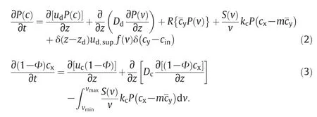
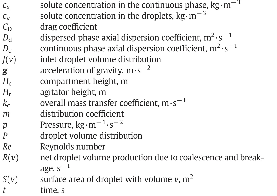
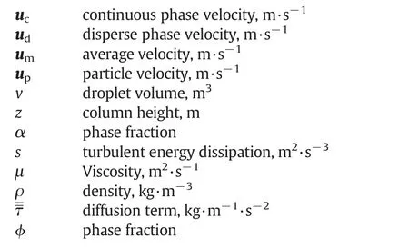
In the lineardriving force model,the overallmasstransfercoefficient is defined by kc,the solute concentration in the continuous phase is given by cxand the distribution coefficient is m.In addition,the surface area of droplets ofvolume v is given by S.The average solute concentration for alldroplets having volume in the range(v,v+d v)at level z is given byThe source term accounting for coalescence and breakage accounts in this context the mass transfer.In the given continuous phase solute balance(Eq.(3)),the axial dispersion is given by Dc.In addition the hold-up ofdispersed phase is defined by:

where vminand vmaxare the minimum and maximum dropletvolumes.The above equations can be easily adapted to any arbitrary column geometry when exchanging the required kernels for breakage and coalescence,energy dissipation,dropletvelocity,mass transfer correlations and axialdispersion[11].
3.3-D CFD Modeling of Solvent Extraction Columns
3-D CFD simulations allow a description ofcolumn hydrodynamics without any geometricalconstraints,where the geometricalpossibilities are mainly limited by computationalresources.The investigations of stirred solvent extraction columns started in 1993 with a publication of Weiss&Bart[12]describing the simulation of a single segment of an rotating disc contactor(RDC)column with the CFD code Fire.Rieger etal.[13]simulated a DN150 RDC column atlow hold-up and employed the Euler–Euler model to predict the two-phase flow structure.Yundong et al.[14]measured and simulated the pro file in a computationaltwo dimensionalrepresented RDC column using the CFD code PHOENICS.A validation of the velocity field was performed using the laser induced anemometer(LDA)-measurements of Fei et al.[15]with single phase flow in stirred solvent extraction columns.The residence time distribution was numerically and experimentally investigated by Modes&Bart[16]and recently by Gurker&Marr[17].The two-phase flow field was simulated by You&Xiao[18].Ghaniyari-Benis et al.[19]simulated an RDC column using the Euler–Euler approach.The first study using CFD simulations for the optimization of solventextraction columns was undertaken by Kolb[20]for a mini-plant Kühni column.An early extension of the two-phase flow accounting the droplet size distribution was reached by Vikhansky et al.[21].Drumm[22]further extended CFD/DPBMresearch.Therefore,he implemented and applied several DPBM using the commercial CFD code FLUENT for the simulation of the droplet interactions in an RDC column.The concept of Kolb[20]and Drumm[22]was applied by Aksamija&Siebenhofer[23]for the optimization of an RDC column,where it could be shown that a stator less design could outperform the stateof-the-art design by 36%with regard to the HTU value.A firstcombination using a commercial CFD/DPBM/mass transfer code for the investigation of solvent extraction columns was done by Hlawitschka&Bart[24]and Jildeh et al.[25].A further improvement regarding the simulation setup,computationaltime and flexibility can be reached by the extension of an OpenSource CFD code[26],namely OpenFOAM®(v171).The numerical framework of the modified “twoPhaseEulerFoam”code is based on a set of continuity and momentum equations for each phase.
The continuity equation for the continuous phase is represented by:

where S represents the source term due to possible mass transfer.The phase fraction in Eq.(5)is represented byαc,the density of the continuous phase byρcand the velocity of the continuous phase by uc.The respective momentum conservation equation is given by:

In addition,the volume fraction mustsatisfy the following constraint for the given two phase flow:

As previously stated in the works of Drumm[22]and the work of Wang&Mao[27],the dominant interphase interaction in agitated extraction columns is the drag force,which is calculated by

In the smaller sized columns with small sized rising droplets(<5 mm),the drag coefficient CDobtained by the modelof Schiller&Naumann[28]can be used:

where the Reynolds number,Re,is defined as

Agitator movement is accounted for by the moving reference frame(MRF),where the rotation of the agitator is accounted for by source terms to the surrounding fluid.Turbulence is accounted by the mixture k-εmodel.The transportequation for the turbulent kinetic energy is given as:

The density,viscosity and velocity are replaced by the mixture density,viscosity and velocity to accountfor the in fluences of the dispersed phase.The transport equation for the turbulent energy dissipation instead is derived from physicalreasons[29]:

where the turbulent viscosity in Eq.(12)is modeled as:

The generation ofturbulentkinetic energy is derived from the mean rate-of-strain tensor:

The modelconstants,which also have been applied in this work,are given as:

The mesh generation was optimized for the two Kühniand a RDC column from a single mesh generation for each column design to an automated mesh generation allowing a flexible design of the internals which is shown in Fig.1 for the Kühniminiplant column(DN32,compartment height:28 mm)with different agitator baffle heights.In total,the column is represented by eight compartments,as well as in flow and out flow zones.Note that Fig.1 shows the fourth lowest compartment.It can be observed that the velocity inside a single compartment increases with increased agitator baffle heights.Besides the local hydrodynamics,the axialdis persion coefficient is a key value for liquid–liquid extraction column layout and is also required for the 1-Dapproach.It can be obtained by an additional Euler–Lagrange simulation.The main force balance equation for the Lagrangian particles is:

where FDrepresents the drag force per unit particle mass:

In Eq.(15),u is the fluid-phase velocity and upis the particle velocity.The molecular viscosity of the fluid isμ.The densitiesρ and ρpdescribe the densities of the fluid and particle respectively.The relative Reynolds number and drag coefficient are set as per the Eulerian model.For the determination of the axialdispersion coefficient,the Lagrangian particles were introduced as a Dirac function at the top of the column.The Lagrangian particles follow the continuous phase down the column and are tracked close to the out flow.The resulting distribution is then used to calculate the axialdispersion coefficient.For the three presented geometries,only a slight deviation in the axialdispersion coefficient of the continuous phase can be observed for 3.0 mm and 4.5 mm baffle heights(Fig.2).The axialdispersion coefficient increases by 20%,when the heightis increased to 8.0 mm.Also the effect ofdifferent compartmentheights can be studied using CFD simulations.In general,an increase of the axialdispersion coefficient can be observed at higher compartment heights and higher rotational speeds(Fig.3),which also results from changes in the local flow structure resulting in larger dead zones underneath the stator plates.For the originaldesign of the Kühniminiplant column(compartment height 28 mm,baffle height:4.5 mm),the 3-D-CFD results follow the trend of the axialdispersion coefficient correlation developed by Breysee et al.[30].

Fig.2.In fluence of the agitator baffle height on the axial dispersion coefficient(6 m3·m-2·h-1).
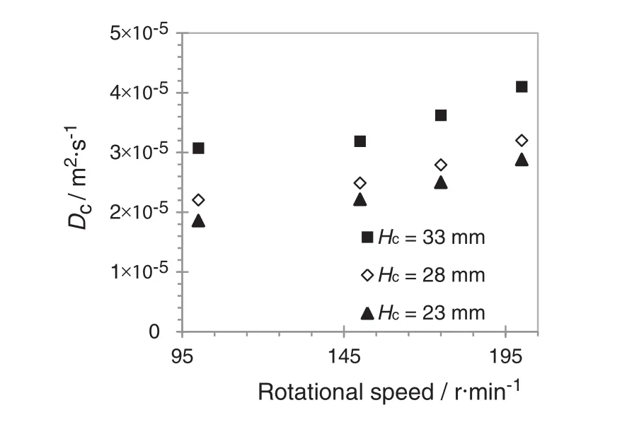
Fig.3.In fluence of the compartment height to the axial dispersion coefficient(5 m3·m-2·h-1)at a baffle height of 4.5 mm.
4.Combination of Both Approaches

Fig.1.Velocity fields in a Kühnimini-plantcolumn atdifferentagitator designs(baffle heights)at6 m3·m-2·h-1 and a rotationalspeed of200 r·min-1 ata constantcom partmen the ight of28 mm.
Both approaches,the 1-D and 3-D,have advantages and disadvantages concerning the computationaleffort,the accuracy and simulation time.The computationaltime for a mass transfer simulation heavily relies on the throughput.A simulation of the finalsteady state of a solvent extraction columns requires a simulation of5–7 times of the residence time of the liquids inside the column.In contrast to this 3-D-CFD simulations are stillbased in literature on the simulation oftime scales in the range of seconds and minutes due to the high computational load.As an example,the required time to reach steady state for a transient fullmini-plant column simulation taking into account the mass transfer is approximated by one month on a modern cluster.The bene fit is the fullresolution of the localhydrodynamics,droplet size and mass transfer.The 1-Dsimulation instead,is able to simulate the transientbehavior of the solute concentration within a few minutes including the simulation setup,but is based on experimentally derived correlations(dropletvelocity,slowing factor,axialdispersion coefficient,energy dissipation,mass transfer coefficient,droplet coalescence and breakup).Therefore,a combination of3-D-CFD and 1-D-CFD seems to be straight forward to reduce experimentaleffortfor the 1-Dsimulation and on the other hand to reduce the computationaltime for mass transfer simulation.The main hydrodynamic correlations as the presented axialdispersion coefficient can be gained by 3-D-CFD simulations,where in addition,different geometricalmodifications can be investigated.The geometry dependentcorrelations for the slowing factor,axialdispersion coefficient and energy dissipation can then be used asan inputfor the 1-D simulation.The concept can be readily extended to droplet resolved 3-D-CFD simulations,to obtain further information about the mass transfer coefficients of single droplets and droplet swarms.
As a proofof concept,Fig.4 shows the resulting dropletsize distribution for a 1-D CFD full Kühniminiplant column simulation(Table 1)compared to experimental data.Fig.5 shows that a high accuracy between the simulated concentration pro file and the experimental data could be obtained by using the mentioned 3-D-CFD correlations.
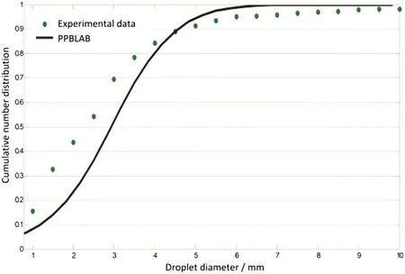
Fig.4.Simulated droplet size using 1-D simulation(Particulate Population Balance Laboratory)as compared to the measured outlet droplet size distribution at 150 r·min-1 and a throughput of 18.7 m3·m-2·h-1.

Table 1 Principaldesign parameters of the used Kühniminiplant column
5.Conclusions

Fig.5.Comparison between the measured concentration pro file and the 1-D simulation(Particulate Population Balance Laboratory)simulation result for 150 r·min-1 and a throughput of 18.7 m3·m-2 · h-1.
The experimentally based design of solvent extraction columns can be supported by numericalmodeling using 1-D and 3-D approaches.The 1-D simulation of solvent extraction columns was facilitated by modern tools using graphicaluser interfaces.The tools allow a description of the hydrodynamics(e.g.holdup),solute concentration and droplet size for different boundary conditions within minutes based on known or experimentalderived correlations.The further development of the 3-D simulation reduces the required number of experimental correlations,due to a direct description of the local hydrodynamics(flow field,energy dissipation).A coupling of the 3-D CFD simulation with DPBMand mass transfer correlations allows the optimization of different column designs,including the column efficiency.Finally,by using the obtained correlations from the 3-D simulations(e.g.axial dispersion coefficients,energy dissipation)in the 1-D simulation,the computationaltime,especially for the mass transfer simulations,is reduced by keeping a good accuracy.The combination of both approaches is evidently the mostpromising technique for future column design.
6.Future Challenges
Despite the promising results using DPBMfor extraction column design and the prediction of mass transfer,the numericalcodes stilldo not cover all the effects observed in solvent extraction columns.Among them are wetting properties,the enrichmentofimpurities,crud formation and entrainment.In addition,these numericaltools were mainly tested for standard testsystems and a common available column geometry.Itwillnotre flectchanges in column design and system properties,such as viscosity,interfacialtension and mass transferrates,occurring in industrialapplications.Afurther task is also the extension of the models to account for reactive extraction,which is essentialfor efficient recovery ofionic species(metalions,organic acids,intermediates)in hydrometallurgy,urban mining,fine chemicals,bio and pharmaceutical fields.
Nomenclature
[1]G.Casamatta,Compartement de la population des gouttes dans une colonne d'extraction(Ph.D.Thesis)Institue National Polytechnique de Toulouse,Toulouse,France,1981.
[2]M.Kalem,F.Buchbender,A.Pfennig,Simulation of hydrodynamics in RDC extraction columns using the simulation tool“ReDrop”,Chem.Eng.Res.Des.89(2011)1–9.
[3]D.Adinata,J.M.Ayesterán,F.Buchbender,M.Kalem,N.Kopriwa,A.Pfennig,Tropfenpopulationsbilanzen zur Auslegung von Extraktionskolonnen,Chem.Ing.Tech.83(7)(2011)1–14.
[4]F.Buchbender,M.Schmidt,T.Steinmetz,A.Pfennig,Simulation von Extraktionskolonnen in der industriellen Praxis,Chem.Ing.Tech.84(4)(2012)540–546.
[5]F.Buchbender,Single-drop-based Modelling of Drop Residence Times in Kühni Columns(Ph.D.Thesis)RTWH Aachen,Aachen,Germany,2013.
[6]M.Attarakih,H.J.Bart,N.Faqir,Numerical solution of the bivariate population balance equation for the interacting hydrodynamics and mass transfer in liquid–liquid extraction columns,Chem.Eng.Sci.61(2006)113–123.
[7]M.M.Attarakih,H.J.Bart,N.M.Faqir,LLECMOD:a Windows-based program for hydrodynamics simulation of liquid–liquid extraction columns,Chem.Eng.Process.45(2006)113–123.
[8]M.M.Attarakih,H.J.Bart,T.Steinmetz,M.Dietzen,N.M.Faqir,LLECMOD:a bivariate population balance simulation toolfor liquid-liquid extraction columns,Open Chem.Eng.J.2(2008)10–34.
[9]M.Jaradat,M.Attarakih,H.J.Bart,Effect ofphase dispersion and mass transfer direction on steady state RDC performance using population balance modelling,Chem.Eng.J.165(2)(2010)379–387.
[10]M.Jaradat,M.Attarakih,H.-J.Bart,Advanced prediction ofpulsed(packed and sieve plate)extraction columns performance using population balance modelling,Chem.Eng.Res.Des.89(2011)2752–2760.
[11]M.Attarakih,S.Al-Zyod,M.Abu-Khader,H.J.Bart,PPBLAB:a new multivariate population balance environment for particulate system modelling and simulation,Procedia Eng.42(2012)1574–1591.
[12]C.Weiss,H.J.Bart,in:D.H.Logsdail,M.J.Slater(Eds.),Solvent Extraction in the Process Industry,Elsevier Applied Science,London 1993,pp.1191–1197.
[13]R.Rieger,C.Weiss,G.Wigley,H.J.Bart,R.Marr,Investigating the process of liquid–liquid extraction by means ofcomputational fluid dynamics,Comput.Chem.Eng.20(12)(1996)1467–1475.
[14]W.Yundong,F.Weiyang,D.Youyuan,W.Jiading,Numericalsimulation and experimental investigation of velocity fields in a rotating disc contactor,Tsinghua Sci.Technol.1(4)(1996)323–326.
[15]W.Y.Fei,Y.D.Wang,Y.K.Wan,Physicalmodelling and numerical simulation of velocity fields in Rotating Disc Contactor via CFD simulation and LDV measurement,Chem.Eng.J.78(2-3)(2000)131–139.
[16]G.Modes,H.J.Bart,CFD-simulation of non-ideal dispersed phase flow in stirred extraction columns,Chem.Eng.Technol.24(12)(2001)1242–1245.
[17]T.Gurker,R.Marr,Aufbau und Vermessung einer 150 mm Labor RDC Kolonne und Vergleich mittels CFD-Simulation,Chem.Ing.Tech.81(8)(2009)1090.
[18]X.Y.You,X.Xiao,Simulation of the three-dimensional two-phase flow in stirred extraction columns by Lagrangian–Eulerian method,Chem.Biochem.Eng.Q.19(1)(2005)1–11.
[19]S.Ghaniyari-Benis,N.Hedayat,A.Ziyari,M.Kazemzadeh,M.Sha fiee,Threedimensional simulation of hydrodynamics in a rotating disc contactor using computational fluid dynamics,Chem.Eng.Technol.32(1)(2009)93–102.
[20]P.Kolb,Hydrodynamik und Stoffaustausch in einem gerührten Miniplantextraktor der Bauart Kühni(Ph.D.Thesis)TU Kaiserslautern,Kaiserslautern,Germany,2005.
[21]A.Vikhansky,M.Kraft,M.Simon,S.Schmidt,H.-J.Bart,Population balance modelling of droplet size distribution in a RDC:inverse problem approach,Technical Report 28 c4e-Preprint Series,Cambridge2005.
[22]C.Drumm,Coupling of Computational Fluid Dynamics and Population Balance Modelling for Liquid–Liquid Extraction(Ph.D.Thesis)TU Kaiserslautern,Kaiserslautern,Germany,2010.
[23]E.Aksamija,M.Siebenhofer,Statorlose RDC-Extraktionskolonnen:Design und Betriebscharakteristik,Chem.Ing.Tech.85(9)(2013)1388.
[24]M.W.Hlawitschka,H.J.Bart,CFD-mass transfer simulation of an RDC column,Comp.Aided Chem.Eng.31(2012)920–924.
[25]H.B.Jildeh,M.W.Hlawitschka,M.Attarakih,H.J.Bart,Solution of inverse problem with the one primary and one secondary particle model(OPOSPM)coupled with computational fluid dynamics(CFD),Procedia Eng.42(2012)1692–1710.
[26]M.W.Hlawitschka,Computational Fluid Dynamics Aided Design of Stirred Liquid–Liquid Extraction Columns(Ph.D.Thesis)TU Kaiserslautern,Kaiserslautern,Germany,2013.
[27]F.Wang,Z.S.Mao,Numericaland experimental investigation of liquid–liquid twophase flow in stirred tanks,Ind.Eng.Chem.Res.44(2005)5776–5787.
[28]L.Schiller,Z.Naumann,Über die grundlegenden Berechnungen bei der Schwerkraftaufbereitung,Z.Ver.Dtsch.Ing.77(1935)318.
[29]Fluent Inc.,Fluent 6.2 User's Guide,2005(Lebanon,USA).
[30]J.Breysee,U.Bühlmann,J.C.Godfrey,Axialmixing characteristics of industrialand pilot scale Kühni columns,AIChE Symp.Ser.80(1983)94–101.
 Chinese Journal of Chemical Engineering2016年2期
- Chinese Journal of Chemical Engineering的其它文章
- Experimental evaluation and modeling of liquid jet penetration to estimate droplet size in a three-phase riser reactor
- Analysis of drop deformation dynamics in turbulent flow
- Review on current advances,future challenges and consideration issues for post-combustion CO2 capture using amine-based absorbents☆
- Photorheologically reversible micelle composed ofpolymerizable cationic surfactant and 4-phenylazo benzoic acid☆
- Experimental study on the effects of big particles physical characteristics on the hydraulic transport inside a horizontal pipe
- Relationship between breakthrough curve and adsorption isotherm of Ca(II)imprinted chitosan microspheres for metaladsorption☆
