Experimental evaluation and modeling of liquid jet penetration to estimate droplet size in a three-phase riser reactor
AliAkbar Jamali,Shahrokh Shahhosseini,*,Yaghoub Behjat
1 School of Chemical Engineering,Iran University of Science and Technology(IUST),Tehran,Iran
2 Process Development and Equipment Technology Division,Research Institute of Petroleum Industry,Tehran,Iran
1.Introduction
High efficiency liquid jet spray has considerable practical applications.Spray hydrodynamics due to injection of an evaporative liquid jet play an important role to the quality of multiphase flows.Sprayed liquid jets are frequently used in various fields comprising evaporative cooling,gasi fication,internal combustion engines,space rockets,boilers,industrial furnaces and gas turbines in orderto increase the rates of heat and mass transfer[1].Fluid catalytic cracking(FCC)converts heavier petroleum fractions into valuable products such as gasoline and light olefins.The liquid feedstock is injected into a stream of hot catalytic particles,where it vaporizes and cracks into lower molecular weight products[2].A kinetic model for the FCC reactor was established and model parameters were estimated by plant data[3].The formation of clusters and accumulation of particles near the wall in dense gas–solid flows are inevitable.Liu and Guo found out that a cluster grows up by capturing the particles in the dilute phase due to its lower verticalvelocity[4].Also,Wang and Guo investigated effects of the cluster porosity,inlet gas velocity and temperature,and coke deposition on cracking reactions of the cluster in FCC riser reactors[5].
In many studies,having a droplet mean diameter such as Sauter mean diameter(SMD)is as important as droplet size distribution[6].Although,there is a vast literature on this subject,many studies have also been accomplished to understand the nature of sprays and their effective parameters.However,few studies have been reported on ex perimental estimation of indirect determination of droplet size,using spray pattern visualization,specifically,in a three-phase fluidized bed.
Practical and numerical approaches are used to predictdroplet size.Sellens and Brzustowski[7]and Liand Tankin[8]have independently established two models based on maximum entropy method for predicting droplet size distribution.In addition,other researchers applied this method[9–14].In another work,Aguilar et al.theoretically and experimentally investigated SMDand vaporization rate in cryogenic sprays[15].Sun et al.provided a pragmatic guide to determine the in fluencing factors for achieving an optimized mixing of a jet spray in a con fined cross-flow,but along this line,conducting a cold modelexperiment become necessary[16].In another study,Li et al.assumed the droplet size distribution follow the normal distribution that may be divided even into 11 groups of sizes[17].Another method was proposed by Sivathanu and Gore[18].Their method is among discrete probability function,which divides the spray formation process into deterministic and non-deterministic portions.Sovani et al.investigated droplet size distribution in Newtonian sprays[19,20].Li etal.proposed a numerical model for water spray injecting through a hollow cone spray nozzle[21]to investigate the effects of dropletsize,bed temperature and spray angle.
Several single droplet vaporization analytical and numerical studies have appeared in the literature[11,14,18–20].Iyer etal.have developed a modelto study two-fluid Diesels prays[22].Bossard and Peck investigated experimentally the dropletsize distribution effects on the ethanol spray applying a horizontal flame jet[23].They held the SMD and fuel–air ratio fixed and observed that flame structure,burning rate and gas emissions were strongly affected by droplet size.Hayashi et al.investigated the effects of droplet size distribution and SMD offuel spray on the soot formation[24,25].They used a phase-Doppler anemometer for experiment and conducted 3D direct numerical simulation(DNS).Dynamics of vaporization has been investigated by Deepu et al.in a hotlaminar air jet[26].
Yokota and Matsuoka[27]and Hiroyasu and Arai[28]derived two correlations using their experimental data to calculate angles of spreading of spray at various amounts of high pressure ambient air.Ohrn etal.used 40 different plain-orifice atomizers to examine the effects of nozzle geometry and flow conditions on spray cone angle[29].The main result of their study is the spray cone angle variations with injection pressure in various internal geometries of the atomizers[30].
There are approximately 400 FCC units including 1.9 million metric ton per day,constituting more than 17%of the totaloilre fining capacity[31].The droplet size and spray penetration length(SPL,the distance from injection nozzle to jet nose)are the most important parameters to calculate vaporization time[32].Nozzle geometry has a drastic impact on the bed hydrodynamics at the zone close to the atomizer.
The most efficient models to interpret atomization are Taylor analogy breakup(TAB)and the enhanced-TAB(E-TAB).An alternative to TAB model has been developed by Reitz,named the WAVE breakup model,which considers the breakup of the injected liquid due to the relative velocity between the liquid and other phases[33].The modelassumes that the time of breakup and the drop size are related to the Kelvin–Helmholtz instability developed in the jet.In either the long-wave or the short-wave case,drop breakup and alteration of the distinctdroplets are assumed to behave according to the Weber analysis.During breakup,the diameter of drops obeys the most probable drop size based on the Rosin–Rammler distribution.In addition,droplet properties have an intrinsic dependence on the Ohnesorge number[34–36].
During recent years,phase-Doppler anemometry(PDA)and laser-Doppler anemometry(LDA)were employed for various purposes in practicalstudies[37].Bhowmick et al.measured differential-pressure fluctuation across a fluidized bed via a monitoring technique[38].Lefebvre and Sridhara carried out the first fundamental survey of penetration of multiple jet con figurations[39,40].This fact that penetration length ofmultiple jets in a circular duct was lower than single jet was reported by Sridhara[40].Due to complicated hydrodynamics of the flow in the circulating fluidized bed(CFB),comprehensive reports focused on description of interactions between the phases are insufficient.
The present work establishes severalcold experiments and evaluates some variables affecting on hydrodynamics of a three phase fluidized bed due to spray of liquid species.Two models that take into account heterogeneous vaporization of the liquid drop are proposed.This paper presents a method to estimate the jet penetration depth and the size of evaporating droplets flowing through the riser,both numerically and experimentally.The measured values of JPD are considered as a criterion to assess the model predictions.Moreover,drop size is determined when predicted JPD value becomes equal to the measured JPD.Applying the proposed procedure has some tangible bene fits and can avoid the need to conduct further expensive measurements.Furthermore,two empirical correlations are derived to calculate both JPD and SCA,respectively.
2.Model description
Complicated nature of multiphase flows and the difficulties to solve their mathematical equations prevent to propose a universal model to evaluate the parameters affecting characterizations of multi phase flow in fluidized beds.In this study,hydrodynamic aspects of a three-phase fluidized bed and phase interactions in the riser reactors are evaluated via developing a competent model.Here,the liquid species behavior is interpreted based on mutual interactions between gas–solid flow and an evaporating droplet by the proposed model.The evaporating liquid droplet consisting several layers encounters with fluidized phase(air)and hotsolid particles,so thata heterogeneous vaporization occurs.Developing the present model that is named SHED(single heterogeneous evaporating droplet)modelcan be pro fitable for determining a computational JPD via simulation(comparable with the experimental JPD)and consequently,predicting droplet size in any riser height.
As shown in Fig.1,each layer of a sphericaldrop is considered to be uniform while mass and heat transfer occur at the outer layer.Temperature gradientin interior layers of liquid species is uniform and the liquid drop outer surface never changes.The net mass transfer between the outer layers and gaseous media is equalto the mass loss due to evaporation.
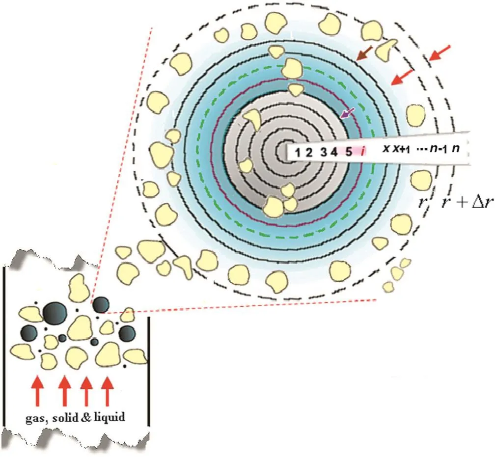
Fig.1.Schematic view of a single heterogeneous evaporating liquid droplet for introducing the SHED model.
Some assumptions in this modelare listed:
-Particle-laden flow due to substantial existence of solid particles
-The riser temperature is constant during fluidization
-The drop is covered by the hot solid particles
-Energy is received via hot solid particles
-Heterogeneous evaporation due to existence of the solids
-The droplet surface temperature is invariant during evaporating
-Binary diffusion with unity Lewis number in the gas phase.
Spraying the droplets onto a dense environment of catalyst particles does notal ways provide proper heat transfer.The best way of ensuring fast vaporization of oil droplets in FCC risers is to spray the droplets onto a stream of solid particles phase with a voidage ranging between 70%and 90%[2,39].The vacuum gasoil(VGO)is dispersed into the riserbottom in the form of drops through a feed nozzle system.The liquid drops contact hot regenerated catalyst particles and are vaporized.The vapor entrains the catalyst particles and catalytic cracking in gaseous phase carried out.In this study,the mean effective diameter of drops(about 200 to 400μm)is much greater than the solid particle diameter(95μm)flowing through the riser reactor.Therefore,it is assumed that the drop is surrounded by the solid particles.
Based on this fact,in the flow field,it is considered because of solid particle-laden flow,a greatnumber of particles are located around a vaporizing droplet,so that the droplets are mainly covered by the solid particles.On the other hand,instantaneous contact between the drop and the solid particles leads to evaporate the drop in an extremely shorttime about0.03 to 0.08 s in accordance with the results of this study.As a droplet appears near to the hot particles,energy is quickly transferred to its surface due to conduction mechanism,and then vaporization starts.The Leiden frost effect obstructs next direct contact between the droplets and the particles.Pushing the particles back due to the force of the vapor flowing outwards from the droplet surface provides rapid outward movement of the solid particles[41].As mentioned,the droplet might be covered by the solid particles due to higher volume fraction of the solid particles that certifies the solid particle-laden flow for fluidized bed.In other words,evaporating liquid phase conveys the solid particles to the top of the vertical standpipe(the riser)[42].Whenever the liquid vaporization occurs due to pressure reduction,the vapor pushes the solid particles back.In this situation,the mechanism of convection through a gas film must also be considered.Hence,utilizing an ordinary relation named Ranz–Marshall's correlation has been applied.Meanwhile,it has been supposed that the liquid species is pure with a single component only.
Fig.1 schematically shows geometry of a single evaporating liquid droplet for introducing the SHED model.Heat and mass transfer rates between the liquid outer layer and its externalmedia are used to simulate the evaporation process of a single heterogeneous evaporating droplet.This model is established based on the conservation laws as follows.
2.1.Governing equations for single drop
The essence of the following mathematicalexpressions is a compact statement of the principles of conservation,with emphasis on the features of transport phenomena.Fundamental attention on the physics,properties,and the boundary conditions can provide usefulresults.
2.1.1.Continuity equation
Based on the mass conservation,the relations with respect to droplet mass variations are represented as

whereρldenotes droplet density at various temperature and pressure for the liquid phase,˙m″denotes the mass flux for the droplet.Note that(r)is the droplet mass flow rate and not the mass flux.Eqs.(1)and(2)are appropriate for describing mass transfer rate from the liquid phase to gas phase.Evaporation via the droplet surface toward bulk when droplet temperature reaches to the boiling temperature is calculated by

where Cd,outand Cd,∞denote the concentration on the outer surface of the droplet and gas boundary surrounding far from the liquid–vapor interface of the droplet,respectively.The evaporation rate of the droplet is computed according to an expression considering the vapor concentration gradient between the droplet surface and the bulk gaseous mixture.
The concentration ofvapor at the dropletsurface is evaluated by assuming that the localvapor pressure at the interface is equalto the saturated vapor pressure at the droplet temperature.The relation is expressed by Psat=Cd,outRTd.In accordance with the famous correlation proposed[43,44]or a more specific correlation so-called the Froessling's equation[29],the mass transfer coefficient,Kc′is calculated with

Where Dddenotes the droplet diameter.The consequentialrelation for considering convective heat transfer,called the Ranz–Marshall's equation is usable[43,45–47].Inasmuch as totalmass transfer belongs to portion of mass transferred from the liquid phase to the gas phase,Eq.(5)is needed.This equation is particularly valuable for finding mass transfer coefficient in situations where Reynolds and Schmidt numbers are available.Both the Sherwood number and the Nusselt number include similar analogy[48].
Finally,the following relations to explain droplet mass changes based on continuity equation are used:

where md,xand n are the mass of the drop and the total number of layers.Combined molar fluxes with respect to molar average velocity are expressed by

Here,Nd,xrepresents netmolar flux from layer x to layer x+1.Molar flux with respect to molar average velocity,Jd,xis also the diffusion flux in the droplet from layer x to layer x+1 and D*denotes molecular diffusion coefficient for the net liquid species as a diffusivity term in the outer layer at every time.
The mass of the dropletis reduced in each step of the dropletvaporization.The mass loss is calculated by reducing dropletradius with time untilthe droplet is entirely evaporated.

Net molar fluxes at the center of the droplet and n th layer are presented as:

In addition to the SHED model,a supplementary model,named spray model,has been developed to simulate the behavior of the spray in detail when the liquid jet flows through the solid and gas phases.
2.1.2.Momentum equation
This modelbased on momentum conservation law considers the effects ofdrag force generation due to interactions between injected liquid,solid particles and gas phases.Both gravitational and drag forces in momentumequations are considered.In presentthree-phase system,there are two drag forces,acting between droplets and gaseous phase and that between droplets and solid phase.
There are various expressions for drag force in the pertinent literature[41].General momentum equation in the riser axial direction based on Newton's second law was presented as

or

Incorporating Eq.(1)into Eq.(12)and making a force balance over the droplet with the aid of other main components in bed can be applicable.When a dropletmoves in the gas–solid flow,the forces acting on itinclude gravity,inter-phase drag.The drag force is in fluenced by the evaporation of liquid,while the portion of the heat transfer between the drop surface and its surrounding media is high enough.When convection heattransfer is the dominant mechanism,the coefficient of drag force over the drop due to the effects of vaporization can be modified[49].
In this work,other forces acting on dispersed phase particles including virtualmass force,liftforce,and Basset history force were not considered due to their slightly magnitude as compared with the drag force term and high ratio discrete phases density to continuous phase.The mentioned forces equate the particles inertia that may be written as below:

The first term in the right side of the above equation is drag force between the liquid and gas phases.The second term is gravitation as the body force,and the last group of the terms in Eq.(13)describes drag force between solid and liquid phases when they make contact with each other.In Eq.(13),Vrsandτsdenote terminal velocity of the solid particles[50]and relaxation time of the solid particles,which is equalto ρsds2/18μg,respectively.Generally,the drag force acting on a particle in fluid–solid systems has been represented by several models.The basic formula of drag coefficient is defined as drag force to dynamic pressure ratio for unit area.Therefore,the drag coefficient between the liquid and gas phases,CD(1)is carefully selected.
The following two drag coefficient models might be applied for gas–liquid flow.The drag coefficient model proposed by Schiller and Naumann for Reynolds number less than 1000 is given below:

Another drag coefficient relation proposed by White and used in this study is expressed by

where C∞is the drag coefficient when the Reynolds number goes to in finity.In calculations C∞is set to 0.5[51].Saboniand Alexandrova presented a drag coefficient for continuous and disperse phases as the following equation[52]:

In addition,there is a drag coefficient between the droplets and solid particles so thatan empiricalrelation including the solid Reynolds number(presented in[50])describes it as

Garside and Al-Dibouniderived a correlation that enables one to get the terminal velocity for the solid phase[50]:

Furthermore,the third terms on the right-hand side of Eq.(13)expressing the behavior of the moving particles with a relative velocity account for the drag force between solid and liquid phases[53].An appropriate coefficient to explain the inter-phase force between the droplet and solid phase is introduced:

Concerning the fluid–fluid inter-phase exchange coefficient,Schiller–Naumann's model[51]as an acceptable method is used.Numerous studies are described in the literature,which address the process at a very fundamental levelconsidering the dynamic phenomena involved at the impact of each single drop of the spray[2,33,54].Also,a comprehensive and systematic review has been reported by Yarin[54].
2.1.3.Energy equation
Consider an air flow system in a fluidized bed with the hot solid particles flowing around vaporizing drops and suppose that the solid particles surface are warmer than the liquid phase,energy is being transferred from the solid phase to the liquid phase.Then the rate ofheat flow across the solid–liquid interface would be expected to depend on the area and interface conditions between each droplet and surrounding solid particles along the flow field.The heat supplied from the hot solid particles diffuses from the drop outer layer into the center.It is applied as the heat source for evaporation of the liquid species.The solids contact with the drop so that a certain amount of heat is exchanged.On the free surface of the drop(that is not covered by the particles),convection heat transfer mechanisms can occur as well.However,since the droplets are mainly covered by the solid particles,the dominant mechanism ofheat transfer is conduction.
Considering sensible heatcontent of the solid particles,when a solid particle is in contact with a droplet the following amount of heat is transferred to the droplet:

whereρ∞is localbulk density in the gas phase.The vaporized liquid is alternatively added to the gas phase(continuous phase)when the entirely drop changes to a vaporous state.The difference between enthalpies of vapor and liquid at saturated temperature and pressure over the droplet outer-surface represents the latentheat of vaporization of droplets,λfg,and theδdenotes a parameter standing for a ratio of vapor volume needed for pushing back the solids to volume of the solids contacted.
Eq.(21)indicates energy lostby the hot small solid particle to liquid phase.During this contact,solid particle is assumed to attain intermediate temperature Tm.As an appropriate approximation,the heat lost by the solid particle can be equated to the energy needed to create vapor of volumeδtimes the solid particle volume based on Eq.(20).

Thus,in this condition,the temperature of solid particle is computed as

Considerable amount of vapor accumulates in a very short time so long as the droplet contact with solid particle.The vapor volume produced is added to gas phase,so that vaporous species along with air makes a gaseous mixture[55,56].The empirical parameterδcan be determined by the following expression:

By considering number of sequential collisions and energy transferred due to allcollisions per unit time,total heat transfer from hot solid particles to evaporating liquid may be estimated by[55,56].
The heat flux from layer x+1 to layer x is described by

The above equation explains the netheattrans ferred to the outer layers.In spite of existence of a particle-laden flow in the riser,energy may be transmitted via convective energy transport.The difference between the temperature of vaporizing species at the outer surface,Tnand temperature at far away from it,T∞is needed to compute transferred heat.The necessary condition for local evaporation is the outer surface temperature of the dropletthat reaches to the vaporization temperature,where the entire drop is changed to a vaporous state.At which,the equilibrium vapor pressure between liquid and its vapor is equaled to the external pressure on the liquid species.Hence,at the liquid–vapor interface,the liquid surface is assumed to be at the boiling point.To calculate the liquid drop diameter passing through the riser,the following equations by the chain rule of partialdifferentiation can be applied:

The quantity within curly brackets is called the Spalding mass transfer number,and is denoted by B as Spalding's coefficient.An alternative expression may be used for estimating mass transferred from liquid phase to gas phase.The relation between Spalding's coefficient and mass flow rate of the droplet has been explained by Langmuir et al.[57]as

where tdsignifies droplet lifetime in terms of seconds.Eq.(28)can be applied to compute energy in spherical coordinate:

The net rate of mass production by chemical reaction per unit volume is equal to zero.The first and the second terms in the left hand side are rate of sensible enthalpy transport per unit volume,in a radial manner.According to the key assumptions in the development and simplification of Shvab–Zeldovich's equations[58],Lewis number is to be unity.The Lewis number is the ratio of the rmaldiffusivity to mass diffusivity,Le=α/D=Sc/Pr,which is used to characterize fluid flow.In other words,the Lewis numberplays an importantrole in simultaneous heat and mass transfer.This assumption enables us to substitute k/Cpinstead ofρDm*in the second term of the left hand side of Eq.(29).
2.1.4.Energy balance at the gaseous boundary
By considering both suppositions of pure vaporization with no chemical reaction and the above assumption,the following equation is derived:

There are two boundary conditions as:T(r→ ∞)=T∞and T(r→rs)=Tboilfor solving Eq.(30)in gaseous phase.If de fining Ω =Cpf/4π ·kf,the radialtem perature pro file is given by

The dropletradius at the liquid–vapor interface is denoted by rsand both Cpfand kf,are calculated by using Eqs.(46a)and(46b).
Inasmuch as the liquid dropletreceives high amountenergy via conduction,evaporation instantaneously takes place on the liquid outer layer.Heat transfer mechanisms including conduction and convection occurred during droplet vaporization in its total form is expressed as

The difference between enthalpies of vapor and liquid at saturated temperature and pressure over the droplet outer surface represents the latent heat of vaporization for droplet,having the dimension of Q/M.The droplet surface temperature is assumed that be nearly the boiling point of the liquid feed.Because of adjacent species(solid-drop)and the least contact with the surrounding gas,conduction is the dominant mechanism for heat transfer.By differentiating Eq.(31),we have

Low-amount limit but significant for mass transferred from liquid drop letto gaseous mixture is considerable for determining radial pro file of temperature in gaseous boundary of the droplet.Eq.(32)can be used to calculate the net energy transferred to the interface,if the evaporation rate,is calculated.By substituting Eqs.(31)and(33)into(32)we obtain

Spalding's classical stand point has been introduced for a single liquid droplet in a quiescent environment.The assumption of quasisteady has been used in this approach forvapor mass fraction evaluating around the evaporating liquid droplet[47],where single liquid droplet situated in a warm air environment has been heated up by hot solid particles.
The drag force is in fluenced by the evaporation of liquid,while the portion of the heat transfer between the drop surface and its surrounding media is high enough.When convection heat transfer is the dominant mechanism,the coefficient of drag force over the drop due to the effects of vaporization can be modified to[1]

2.2.Droplet diameter variation
Both Eqs.(1)and(2)can be applied to compute droplet lifetime from partialevaporation stage to to taleva poration.Using Eq.(27)and its differentiation[58]yields the below expressions:

The quantity within braces denoted in terms ofΛis called evaporation constant,having the dimension(L2/t).Integration of Eq.(37)results in

Eq.(38)as a non linear correlation that called D2-law is suitable for calculating vaporizing droplet diameter[58].This equation implies that the initialsize of a dropletis D0and the diameter decreases as the droplet move up through the riser.In this work,an individual verticalposition in the riser where the droplet diameter is equalto zero is called jet penetration depth(JPD).For every intermediate time of droplet vaporization,SPL as a certain distance from injection position is available:

With regard to definition of droplet velocity that is the sum of the conjugate distances of verticalcom ponents of velocity vector,JPD and the droplet diameter variations versus any length of riser can be obtained under the conditions of Eq.(40):

There are more detailed information on the design aspects of different atomizer types with various structures including single-hole,multi-hole,conical and annular spray,pintle,swirl and impinging jet injectors,as well as pressure air-blast plain orifice and prefilming atomizers[1,59,60].To calculate the mean size of drops coming out of the nozzle orifice,a few empirical correlations have been reported based on separated experimental works[39,61],especially for liquids of low and high viscosity.For atomizing low-viscosity liquid,Lorenzetto&Lefe bvre and Jasuja proposed Eqs.(41)[39,62]and(42)[30,63],respectively.Both the empirical correlations are applicable for the nozzles with low-viscosity liquid flow.It is assumed that a drop has the same ratio of(volume/surface)as the entire spray.
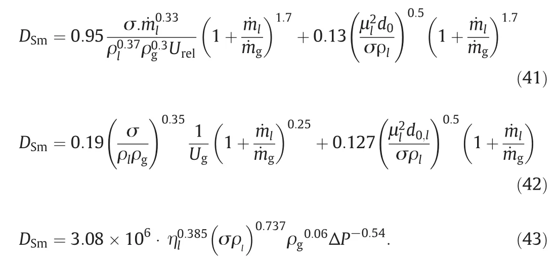
In these correlations,surface tension,kinematic and dynamic viscosities associated with liquid and the mass flow rate and density of both gas and liquid species as well as the liquid jet diameter are parameters affecting on SMD.The context of Lorenzetto et al.and Jasuja's expressions[39,61–63]reveals an obvious concept in comparison with Elkotb's correlation(Eq.(43))[64],so that liquid-to-gas mass flow ratio is the most significant factor affecting on DSm.Increasing air–liquid ratio(ALR)and declining liquid flow rate lead to improving atomization quality.In addition,SMD is increased due to increasing liquid viscosity[62]and surface tension[60].According to an experimental investigation,El-Shana wany found that for low-viscosity liquids,SMD is proportionalto[60].
In many spray nozzles,a liquid is forced through an orifice.These types of nozzles form a liquid jet at low injection pressures.Therefore,the instability theory of liquid jets is used as a firs testimate of the droplets that may be formed by these nozzles[33].The larger drops break up into smaller droplets until they reach a state ats pray form.The primary breakup of drop possesses an initiallength known the breakup length.This length is a criterion for computation of DSm.Levich[65]proposed an empirical correlation for the jet breakup length(u0denotes discharge speed at the nozzle):

The feedstock nozzles are designed in different aspects to enhance FCC unit efficiency.Since the injectors with smallsize orifices lead to producing finer droplets,nozzle calculations are encountered with further difficulties for SMD.For liquids with higher viscosity,El-kotb[12]has applied some experimental data and proposed an appropriate correlation(Eq.(43))to calculate DSm.Eq.(43)is not directly used in present work,due to the absence of proper conditions(the liquid high viscosity).Up to the presenttime,many different equations are reported to compute droplet mean diameter[11,39].In this work,a computationalapproach is applied to calculate droplet mean diameter,Dm,as given by the following equation:

Based on thermo-physical properties,the following equationscan be applied to calculate the heat capacity,Cpfand the the rmalconductivity,kf,as functions of fluid temperature(K):

There is an important approach to determine various flow regimes of heat and mass transfers between continuous phase(gas)and dispersed phase,given as three different models in literature.These models are categorized based on droplet temperature comprising called as inert heating model,drop vaporization model and boiling from the drop model.The solid particle characteristics comprising solid flux,phase holdup,diameter,heatcapacity and density as well as contact between the particles and the drop determine the quality of process[56].However,effect of heat transferred from hot solids due to more loading up 1%leads to decrease spray tip penetration(STP)as given by

where PD,and PD,freedenote JPD with and without the solid loading in fluidized bed,respectively.
2.3.Experiment alapparatus and method
Schematic diagram of an experimental set-up is demonstrated in Fig.2.The fluidized bed is a verticalcylinder with a length of1.132 m and outer and inner diameter equalto 0.076 m and 0.08 m,respectively.In the experimental set-up,the Freon-22(liquid)is supplied from a high-pressure tank,about 1.14 MPa gauge pressure.CFC-22(R22)is a single component with low ozone depletion potential[66].The flow of the solid particles and air then meets the injected liquid Freon producing a three-phase flow that moves up the riser.The injector utilized in cold test has a circular aperture(0.9 mm diameter),which is used to injecta high velocity and round jet into the riser.
A CASIOEXILIMEX-F1 camera(300 up to 600 fps)was utilized to record the liquid jet movements and to observe the spray tip penetration.High-speed camera along with a related program can produce a pictorial stream including separated digital images with a resolution of 512×384.Three J-type thermocouples from Fluke®instrument group and a digitaltemperature meters from KI&BNT®were applied in this set-up.To evaluate pressure of the liquid flowing through the copper tubes a digital manometer(R-610,P&M®)was used and a fast visible dialpressure gauge presented by PAKKENS®was employed.
Three phase flow experiments were conducted to investigate the effects of solid particles on spray pattern in the bed.The glass riser was used to perceive and record the flow pattern by a high resolution camera.This riser has three inlets;liquid phase(Freon)inlet,gas(air)inletand solid particle(alumina,inert FCC catalyst)inlet.Working temperature range was 270–275 Kfor liquid injection.In this work,the solid minute particles were 95 micron alumina in spherical shape.In this study,jet penetration depth was experimentally measured using an image processing method.Fig.3 shows the imaging system applied to detect the sprayed jet penetration depth.A visualmethod for indirect determination of the droplet size is proposed to take non-interrupted pictorial stream of the jet flow.The camera can record high-speed movies and deliver slow-motion footage of each object or break it down to snapshots.Jet penetration depth(JPD)measurement error was determined in a range from 0 to 2.7 mm.
The primary experimental data showed that photography of the interior of the fluidized bed involved some important matters such as exposure time to be adjusted.The recording speed is in a range of300 up to 600 fps.Therefore,the exposure time was set in a desirable amount up to 1.6 ms via adjusting camera shutter.To acquire more accuracy,five pairs of sequential frames were considered for image processing.Then the results were compared with the simulation results.Allof the riser entrances were connected to an A/Dconverter.Activating six channels(of16 channels)related to a USB 4716 converter(16 bit,200 kHz)designed by Advantech®leads to data acquisition from sensors.
Most of the atomizers such as plain-orifice atomizers discharge liquid species in a form nearly similar to conical geometry,as shown in Fig.3.The spray cone formed in plain-orifice atomizers is slender.Then the droplets are dispersed throughout the spray volume.Jet structuring and spray patterning are completely relevantto nozzle geometry,liquid specifications,and gas phase properties.The angle of the spray is normally defined as the angle formed by two straight lines drawn from the discharge orifice to the points where the spray is at a distance 60 times of aperture diameter of the atomizer from the orifice,as shown in Fig.4(a)and(b).A few correlations have been proposed in terms of atomizer dimensions to depict the spray cone angle(SCA).In the basis of the jet mixing theory of Abramovich[30],a good expression for the spray cone angle,has been introduced in the following simple form:


Fig.2.Schematic views of a)experimenta lset-up and b)the structure and dimension of the nozzle.Alldimensions are in mm unless otherwise noted.

Fig.3.Exemplified snapshot due to image processing concerning a sample of liquid jetting and formation of a full-cone spray in a gas–solid fluidized bed.
Dimensions and geometry of an atomizer,especially,exit aperture size are effective parameters in jet spreading angle calculation.It is tried to fix operational conditions and quantities of boundaries along experiments.The injector utilized in cold test has a circular aperture(0.9 mm diameter),which is used to inject a high velocity and round jetin to the riser.Pressure atomizers or plain orifices are the most prevalently used atomizers due to their simplicity and ease of manufacture proper for industrialspraying[67].
In the present work,to compute spray cone angle as a function of various parameters including air viscosity and density,nozzle orifice diameter and the pressure difference between ambient air and injected fluid,an empirical correlation has been proposed.Fig.4(a)indicates the area of a triangle based on the method of Heron(Greek mathematician)in order to compute spray cone angle[68].To describe spray cone angle the following formulas are introduced:

where S and P denote area and perimeter of depicted triangle as well as p is semi-perimeter and hal fangle faced to the base of the triangle,βcon/2 equals to amount of(90-φ),as shown in Fig.4(a).In addition,schematic views of Fig.4(b)and(c)show jetangle in injection position for atomizer having axial flow and full cone spray.
3.Results and discussion
Some specified parameters may be considered for numerical and experimentalanalysis in present work.The ranges in Table 1,due to some feasibility conditions and implementation constraints in the cold experiments,have been selected and performed.

Table 1 Some parameters used for numerical and experimental analysis in present work
In this study,several experiments were conducted relative to the reference conditions in Table 2 to investigate the effects of some parameters on fluidized bed hydrodynamics.When a parameter is varied from the reference condition,it will be noted in the text or captions.
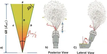
Fig.4.Schematic views for illustrating a)diagrammatic calculation of spray cone angle,b)and c)the injector view located in injection position along with its posterior and lateral sceneries.
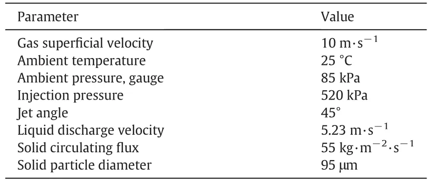
Table 2 Reference conditions
3.1.Modelvalidation
Experimental data were employed to validate the results due to solution of the model.The mathematical code,developed in this work,was used to solve the model.Table 3 indicates conventional range of the independent variables,applied in both mathematical model and experiments.

Table 3 The ranges of the independent variables
In stable conditions,44 experiments with differentinputparameters(fixed or not)were conducted to create desirable images in order to evaluate the developed model.Fig.5 displays that the deviation of the modelpredictions from the experimental data is more significant for higher values of jet penetration depth.On the other hand,higher spray length occurs when fluidized bed have greater air velocity,jet angle and spray pressure as well as less solid mass flow rate.Here,the mean relative error between the predictions of the model and the experimentalresults was calculated as 4.3%.

Fig.5.Demonstration of comparing spray penetration length versus measured values and predicted values.
Spray penetration length(SPL)versus gas super ficial velocity is shown in Fig.6.This figure indicates the penetration length is elevated as air velocity increases.It also displays good agreement between the model predictions and experimental data.

Fig.6.Comparison between model predictions with the experimental data.Injection pressure=520 kPa,jetangle=45°,liquid injection velocity=5.23 m·s-1,solid circulating flux=55 kg·m-1·s-1,and solid particle diameter=95 μm.
Referring to the importance and attempts of many researches for tracing the paths of round jets injected at various jet angles into the flowing airstreams,Fig.7 shows a comparison between modelpredictions and the experimental data for SPL versus different jet angles.It is indicated that there is a reasonable agreement between these results.It also implies that increasing the jet angle elevates the penetration length.
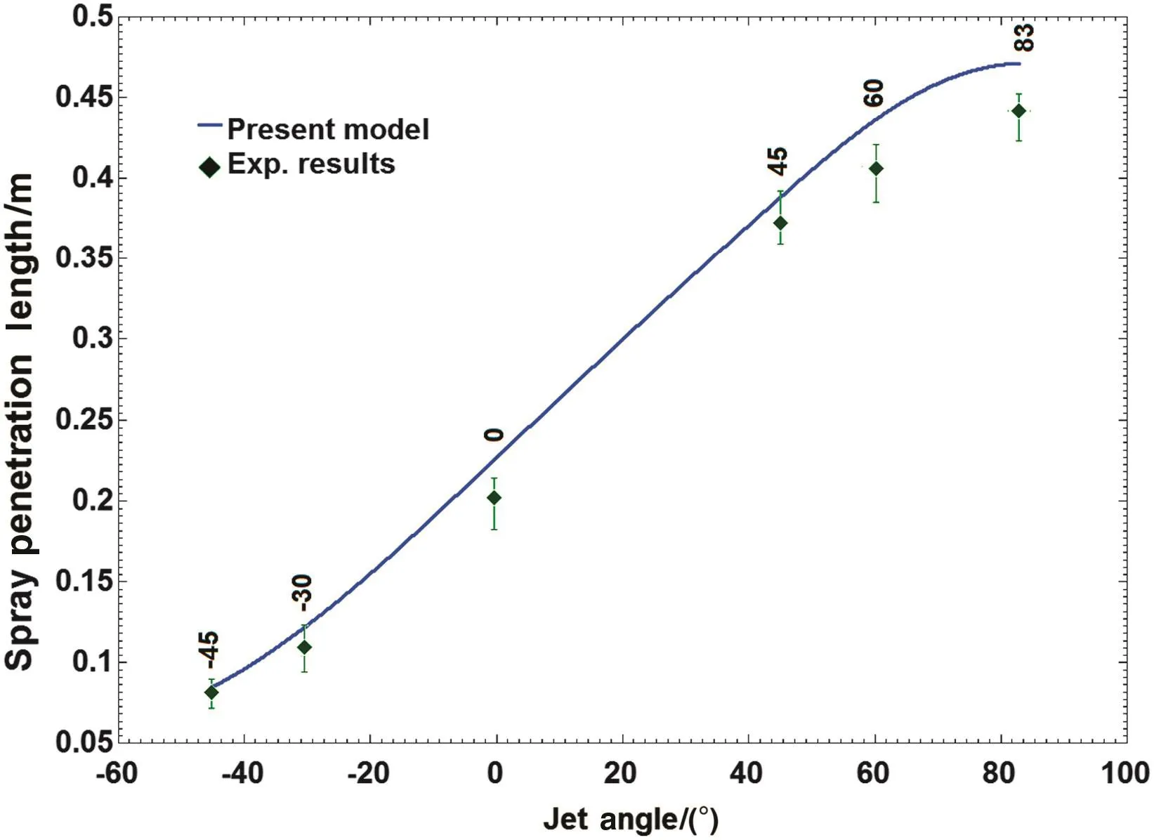
Fig.7.Comparison between model predictions with the experimental data.Conditions:gas super ficialvelocity=10 m·s-1,injection pressure=520 kPa,liquid injection velocity=5.23 m·s-1,solid loading=55 kg·m-2·s-1 and solid particle diameter=95μm.
In both Figs.6 and 7,it is seen thatfor largervalues of air velocity and jet angle,the deviation between the experimental data and the predictions is higher.This can be described by practicallimitation to observe a cloudy region at the top to the spray.At very high air velocity and jet angle,image processing of the spray in the bed is almost impossible at the spray tip because at this levela distinct boundary cannot be identified.In Figs.6 and 7,only one independent variable comprising gas super ficialvelocity and jetangle is not fixed and the others are considered as constant parameters.The constant parameters are introduced in Table 2 as reference conditions.One of the most important parameters to ensure the accuracy of the presented modelis estimating the droplet mean diameter.Fig.8 shows droplet mean diameter calculated using Eq.(45)versus various gas super ficial velocities.The curves of Fig.8 have similartrends indicating that Eq.(45)can predict dropletmean diameter with accuracy close to those of Eqs.(41)and(42).

Fig.8.Droplet mean diameter versus different air super ficialvelocity.Conditions:injection pressure=520 kPa,liquid injection velocity=5.23 m·s-1,ambient gauge pressure=85 kPa,jet angle=83°,solid loading=55 kg·m-2·s-1 and solid particle diameter=95μm.
As the fifth aspectof validations,according to experimental observations was seen thatin fluencing heat transferred from hot solids due to more solids loading up 1%leads to decrease STP.Adding first halfpercent of volume fraction of the solids leads to a declination in STP,nearly 25%of liquid jet height in comparison with a particle-free flow.From this time forth,further enhancing mass flow rate(more loading)has a lowerim pacton JPD.Wang etal.also numerically showed trend of effect of solid loading on spray penetration[69],similar to the present data.
3.2.Effect of layer number
The SHED modelcontem plates an evaporating liquid droplet that consists of several layers.Fig.9 shows relationship between SPL and layer number for an experimental run,illustrating that the predicted JPD is not dependent to the layer number variation when it is large enough.This certifies the necessity of having a multi-layer model for achieving accurate JPD simulation.
One of the advantages of having the multilayer modelis a possibility for finding size of a single drop along the riser versus different heights.Thus,droplet size dependency to the bed height(droplet lifetime)leads to compute the droplet diameter at any height of the spray region.

Fig.9.Demonstration of jet penetration depth versus layer number.Conditions:air velocity=10 m·s-1,injection pressure=520 kPa,jet angle=45°,liquid injection velocity=5.23 m·s-1,solid loading=55 kg·m-2·s-1 and solid particle diameter=95μm.
Due to high volume fraction of gas phase in comparison with holdup of the liquid and solid phases,the bed temperature is assumed to remain invariant and equalto 25°C,during the experiments.Fig.10 illustrates radial pro file of instantaneous temperature at gaseous boundary of an evaporating droplet having various sizes when there is pure vaporization without any chemicalreaction in the riser.
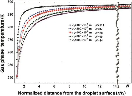
Fig.10.Temperature pro file for gaseous boundary belonged to a liquid evaporating droplet having instantaneous diameters during evaporation.Conditions:air velocity=10 m·s-1,injection pressure=520 kPa,solid circulating flux=55 kg·m-2·s-1,and solid temperature=37°C.
The heat diffusing into the drop applies as the heat source for evaporation of the liquid species.Total received energy is consumed for latent heat of vaporization and then a continuous decrease in size is progressively observed.The latent heat of vaporization is utilized as a function of either temperature or pressure.Under this circumstance,concentration on the outer surface of the evaporating droplet corresponding with its vapor pressure is 0.0523 mol·m-3.
3.3.Parametric study of the variables
Some variables affecting on characteristics of flow in three-phase fluidized bed were studied.The reference conditions given in Table 2 were applied to evaluate the parameters effecting on fluidized bed hydrodynamics.To achieve reasonable results concerning each individual parameter,other parameters were invariant.
3.3.1.Effect of gas super ficialvelocity
The essential force for fluidizing the bed contents is supplied by the gas.The gas flow(the highestholdup),as a dominantphase is uniformly supplied by an aircompressor,ata stable condition of mass flow rate.Different air velocities(6,10,14,and 18 m·s-1)were applied to evaluate JPD.Fig.11 displays spray penetration in the axialdirection(y)and radial direction(z).In this study,it is assumed that liquid droplet diameter in any penetration length of spray(the riser height)is invariant.As demonstrated in Fig.11(a),the curved and straightlines illustrated in the cloudy core of spray(represented by red lines.Please refer to the on line version for the colorized figures)show the trajectory of a typicalsingle droplet,representing other droplets in any height of the riser.The results imply that for a single jetby increasing air velocity,spray penetration in axialdirection is raised and in radialdirection is declined as shown in Fig.11(b).
It is obvious that the gas super ficialvelocity can affect the droplet lifetime.The results show thatby increasing air velocity,the dropletlifetime decreases.Meanwhile,increasing the air velocity leads to generation of smaller droplet at the same time.This effect can accelerate the evaporation process even though in a minor range.Fig.12 shows that the maximum evaporation rate(/max=1)occurs atapproximately a SPL equalto 0.15 m and after that vaporization rate of droplet is relatively low.

Fig.11.Illustration of a)the front and lateralviews of the liquid jet,and b)values of the axialand radialdisplacement of the liquid species versus different conditions of the air velocity.Conditions:ambient gauge pressure=85 kPa,injection pressure=520 kPa,liquid injection velocity=5.23 m·s-1,jet angle=45°,solid circulating flux=55 kg·m-2·s-1 and solid particle diameter=95μm.
In addition,Fig.12 displays that higher droplet velocities can be achieved by increasing air velocity,showing that the droplets at the end of the penetration length have a velocity lower than the air velocity.Increasing air velocity leads to the escalation ofdrag force that in turn causes to raise droplet velocity and length of penetration as indicated by Fig.11.
Fig.13 implies that faster droplet shrinkage at the riser occurs for the lower gas super ficialvelocity,because less turbulence and momentum exchange between the droplet and other components in the bed takes place,leading to more reduction in droplet diameter at any riser height.
3.3.2.Effect of liquid jet velocity
In order to determine variations of the droplet size,evaporation rate,and velocity as well as SPL,severalinjection velocities(4.5,5.2,6.5 and 7.5 m·s-1)were selected.Fig.14 shows that higher injection velocity for liquid jet yields higher spray penetration,and indicates that the greater injection velocities lead to creation of smaller droplets at the same time.
When relative velocity between the evaporating droplet and other phases is very small,the gas flow easily entrains the very small erdroplet and takes it to the upper regions of the riser.If the gas flow velocity is less than the axial component of the liquid velocity,then the droplet velocitydecreases due to the drag force.Contrary to previous state,there is a prompt evaporation process,which happens when liquid species at very high velocities is discharged into a moving air carrying solid particles or when a high-velocity-air flow meets a liquid jet with a suitable angle.Fig.15 shows droplet evaporation trend in any length of the riser in terms of various jet discharge velocities.Figure indicates that vaporization peak for all of the injection velocities occurs almost near to injection position.
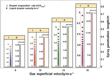
Fig.12.Droplet evaporation rate and liquid droplet velocity versus different gas super ficialvelocities.Conditions:ambient gauge pressure=85 kPa,injection pressure=520 kPa,liquid injection velocity=5.23 m·s-1,and solid circulating flux=55 kg·m-2·s-1.
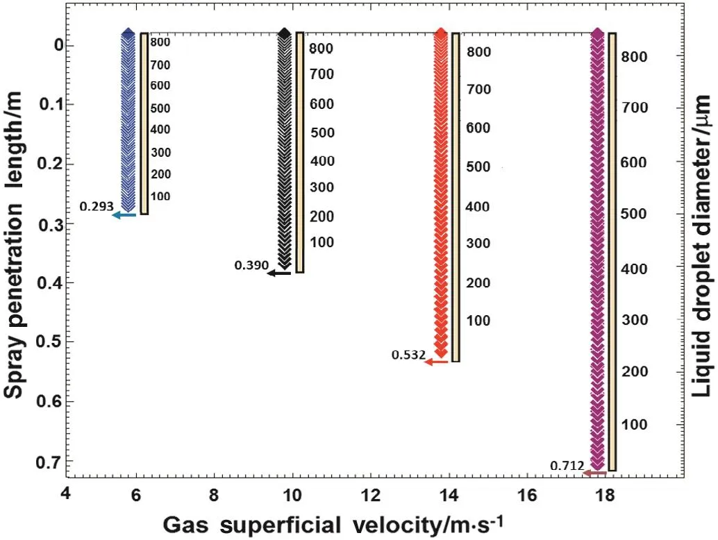
Fig.13.The liquid droplet size versus various gas super ficialvelocities.Conditions:ambient gauge pressure=85 kPa,injection pressure=520 kPa,liquid injection velocity=5.23 m·s-1,and solid circulating flux=55 kg·m-2·s-1.
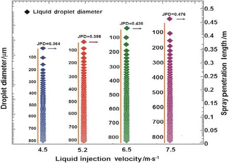
Fig.14.The droplet diameter versus liquid injection velocity.Conditions:ambient gauge pressure=85 kPa,air velocity=10 m·s-1,and solid circulating flux=55 kg·m-2·s-1.
Fig.15 indicates the axialdropletvelocity is dramatically underthe influence of the air velocity when gas super ficialvelocity is based on the reference conditions is attended air inlet velocity to distributer in bed has been kept constant(10 m·s-1).As indicated by the results of figure,because of loweraxialcom ponent of the liquid injection velocity compared to the air velocity,the air is the dominant fluid to fluidize the bed.3.3.3.Effect of liquid volume flow rate
To study the effects of liquid volume flow rate on flow characterizations a range of diameter of nozzle orifice(below 1.4 mm)was selected,so that the jet could have enough pressure at the nozzle to reach a reasonable height of the riser.The amounts of volume flow rate for liquid phase were chosen to be 8.05 ml·s-1(1.4 mm),4.97 ml·s-1(1.1 mm)and 2.92 ml·s-1(0.85 mm).Two middle quantities of 5.91 ml·s-1(1.2 mm)and 3.32 ml·s-1(0.9 mm),peer to each other were later selected to obtain more comprehensive results(curves).Fig.16 shows droplet velocity increase by increasing liquid volume flow rate due to size variations of nozzle orifice.In addition,diagrams imply that the droplet velocity increases with larger acceleration rates at the beginning(the nozzle position).
This figure also indicates thatfor high volume flow rates(more than 8.05 ml·s-1)droplet velocity becomes very close to gas phase velocity(nearly 10 m·s)at the spray tip position due to less initial difference between them.The trend of the two diagrams related to volume flow rates of 3.32 and 2.92 ml·s-1is different from others,since initially the velocity difference between droplets and air is very significant for them,so ittakes time to reach high acceleration rate of the droplets.Another reason for gradual changes of the droplet speed at the beginning and very steep changes of data at the end of the mis that the droplets become smaller and lighter as they move up resulting to more upward force affecting them.
3.3.4.Effect of liquid jet angle
In order to study the effect of this parameter,six different jet angles(-45°,-30°,0°,45°,60°and 83°)were applied in this work.In experiments a plain-orifice atomizer was utilized to inject liquid species at a high velocity and round jet into the riser.Liquid Freon flows through the nozzle with inner diameter equalto 0.9 mm.The schematic views related to nozzle with axial flow for a full cone spray along with introducing jetangle and spray cone angle are demonstrated by Fig.4(b)and(c).When the jet angles change,liquid species may be evaporated faster or slower,and the velocity of liquid droplet reaches almost near to velocity of the dominant flow(gas phase)in the riser.It can be validated that ifjet angle becomes greater,the spray is raised higher along the riser height.
For negative angles,according to Fig.17,the droplets go down after the injection due to initialdroplet velocity and then go up,because of the drag force exerted on them from the air.By increasing the jet angle,spray penetration rises along the riser height and declined along the radialdirection.
It is clear from Fig.18 that the normalized evaporation rate is high at the injection pointand increases to a maximum soon after the injection.Then itdeclines throughout the restof dropletpathway.This figure also indicates that for negative jetting angles(countercurrent spraying)the droplet evaporation occurs in a space around the injection point(5 cm below to 5 cm above of the injection point,approximately).For jet zero-angle(cross flow spraying),the evaporation also takes place in nearly the same space.For the positive angles(concurrent spraying),the evaporation happens in a relatively large area above the injection point.
In addition,Fig.19 presents droplet velocity at different heights versus various jet angles.This figure compares flowing behavior of liquid jet due to direction of jet injection in bed.Obviously,curves belong to positive jet angles show a continuous gradual increase for each injection.For negative angles,there are an initial decay,a point of distinct minimum and a subsequent increase due to velocity of gas phase carrying solid particles.It shows if the jet angle decreases,liquid species is evaporated faster and its velocity reaches almost near the velocity of dominant flow.It is clear that,for jetangles greater than zero,spray penetration is more raised along the riser height.
3.3.5.Effect of injection pressure
To investigate the impact of the liquid injection pressure,as shown in Fig.20,various pressures(five values)were considered.The velocity of the liquid species passing through the nozzle can decrease because of reduction ofu pstream pressure and the pressure difference between interior channelof the nozzle and the bed.The velocity of the liquid flow,discharging from the nozzle,while is encountered with fluidized air,is continuously increased in the direction of the upward flow passing through the riser reactor.Fig.20 also shows when upstream pressure belonging to the liquid rescuing toward the bed reduces,its penetration depth declines along the riser reactor.In addition,the droplet diameter typically decreases at any cross section of the riser height.
In addition,a corollary resultobtained shows thatinjection pressure mustbe regulated so thatdropletvelocity approaches the airvelocity at the downstream of the riser for effective contact between liquid and solid phases.Combination of both turbulence and externalaerodynamic forces,acting on the liquid jet,leads to break up the jet into droplets in the secondary breakup stage.Under this condition calculating Weber number determines the probability ofoccurring different mechanisms ofbreakup[51].

Fig.15.The droplet velocity values and the normalized evaporation rate of the droplet versus the injection velocity.Conditions:air velocity=10m·s-1,solid circulating flux=55 kg·m-2·s-1 and solid particle diameter=95 μm.
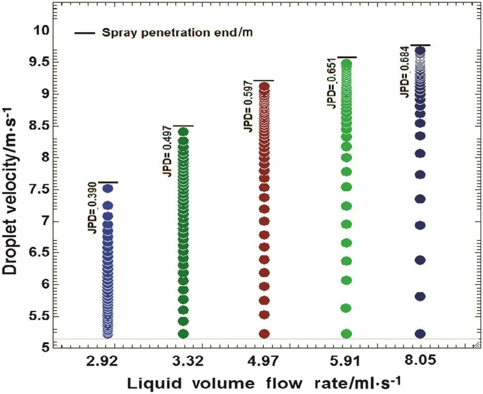
Fig.16.The liquid droplet velocity versus liquid volume flow rate.Conditions:air velocity=10 m·s-1,injection pressure=520 kPa,liquid injection velocity=5.23 m·s-1,jet angle=45°,and solid circulating flux=55 kg·m-2·s-1.
3.3.6.Effect of solid mass flux
The effect of solid holdup was evaluated in terms ofcontactbet ween gas and solid in a certain velocity of gas(air velocity equals to 10 m·s-1).Both fast fluidization(lean core–dense wall)and pneumatic conveying(lean everywhere)regimes can be applied in simulation.Fig.21 shows decreasing solid mass flux causes to extend spray tip penetration to confined quantity.As is shown in the figure,the spray tip penetration could be decreased about 0.13 m of the riser height due to adding only 0.55 kg·s-1of solid particles.Although in a general glance,because of higher volume fraction of the solids,may be supposed to STP increases,but considering impinging and effects of heat transferred from hotsolid particles obtains different results.Similar to these results,Wang et al.showed effect of solid loading on SPL[69].According to the experimental observations,it is obvious that proportionalto spray structure,initially the spray size is higher and then the evaporating spray is contracted and its tip turns to be shorter.Here,enhancing 0.5%solid loading leads to a declination in STP,approximately 25%against a case of particlefree.Further increase in the solid mass flow rate has minimalimpact on JPD.Proportionalto both solid loading and super ficial gas velocity higher,regime of fluidized bed may be included turbulent,fast fluidization or pneumatic conveying.This fact that penetration length of multiple jets in a circular ductis lower than single jet was found by Sridhara[40].Then,Sridhara ascribed this to the obstruction effect of the jets in creating a local increase regarding velocity in field flow.
3.4.Correlations
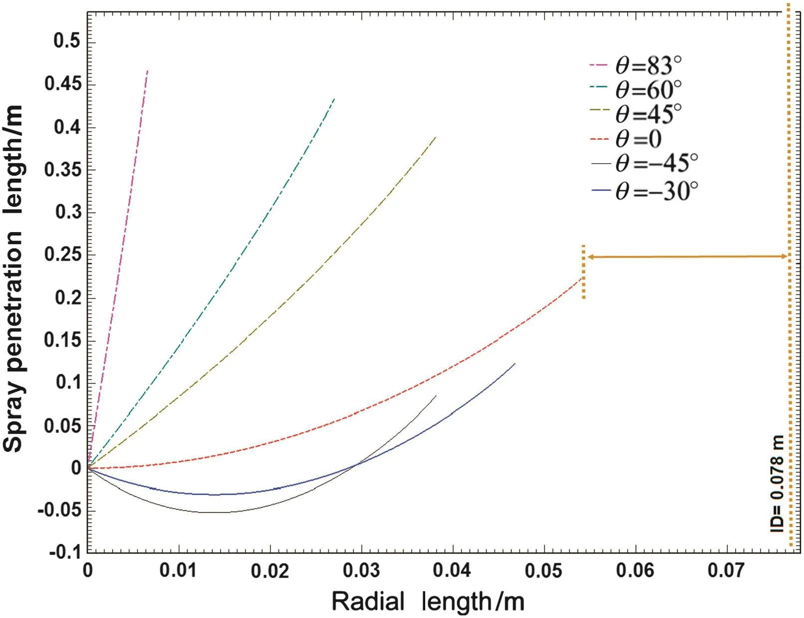
Fig.17.SPL versus radial length of the riser.Conditions:bed inner diameter(ID)=0.078 m,air velocity=10 m·s-1,injection pressure=0.520 MPa,liquid injection velocity=5.23 m·s-1,and solid circulating flux=55 kg·m-2·s-1.
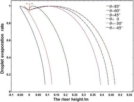
Fig.18.Normalized evaporation rate versus the riser height.Conditions:air velocity=10 m·s-1,injection pressure=520 k Pa,liquid injection velocity=5.23 m·s-1,and solid circulating flux=55 kg·m-2·s-1.
In the following subsections,two empirical expressions are presented for calculation of jet penetration depth and spray cone angle related to an evaporative liquid jetinjected into a gas–solid fluidized bed.These correlations are applicable for the conditions listed in Table 3.
3.4.1.SCA correlation
According to Eq.(48)based on Abramovich's theory of turbulent jets,injection geometrical conditions and ambient pressure have no effect on the spray cone angle calculation.In this work,the results of a captured image by means of a high-resolution camera are used to illustrate how geometrical equations can be applied to calculate spray cone angle.By utilizing dimensional analysis and identified two dimensionless groups as appeared in Eq.(51),44 experiments were conducted to create 44 images similar to the image of Fig.3.Then,44 spray cone angles were calculated from these images and the Heron's method in accordance with Fig.4(a).It was applied to develop an empirical correlation of spray cone angle as a power law function of several parameters βcon=F(Δp,ρair,darf,μair),as given below:in which the average pressure difference,Δp,depends on liquid temperature,nozzle discharge conditions,and gas phase in the riser.Eq.(51)implies that increasing pressure difference between liquid jet and surrounding air leads to higher SCA.One of the advantages regardingβconcalculation is that it can be used to compute the amount of the air transferred into the liquid jet.The mean relative error between the spray cone angle correlation and experimental data was 3.9%.

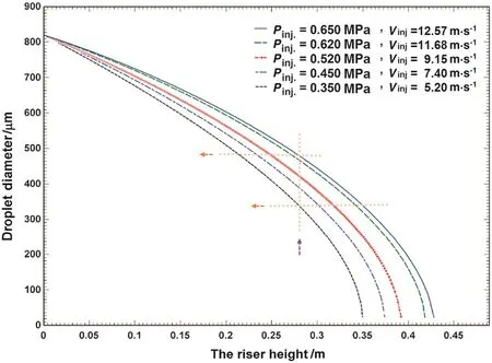
Fig.20.The evaporating liquid droplet size versus the riser height.Conditions:gas superficial velocity=10 m·s-1,jetangle=45°,average bed pressure=130 kPa,and solid circulating flux=55 kg·m-2·s-1.
3.4.2.JPD correlation
The parameters in fluencing on jet penetration depth(JPD)were experimentally investigated.The data were applied to derive a correlation to compute JPD using multiple regression method[70–72].For this empirical correlation,44 experiments were carried out.In each experiment,a photo like Fig.3 was taken while only one parameter was changed from the reference conditions given in Table 2.Jet penetration depth was measured by image processing.JPD was assumed that be a function of four operational parameters in fluidized bed comprising air velocity,liquid injection pressure,jet angle and solid flow rate as factors affecting on the jet penetration.It is clear that the jet velocity is directly dependent on injection pressure[15],so it was not considered as a parameter of this correlation.We assume:
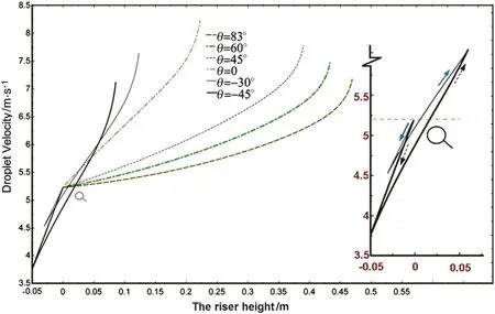
Fig.19.Droplet velocity versus the riser height,demonstrated right-hand curve belongs to grandiose plan for negative angles.Conditions:air velocity=10 m·s-1,injection pressure=520 kPa,liquid injection velocity=5.23 m·s-1,and solid circulating flux=55 kg·m-2·s-1.

Fig.21.The droplet size versus the riser height.Conditions:air velocity=10 m·s-1,jet angle=45°,liquid injection velocity=5.23 m·s-1,and injection pressure=520 kPa.

The variation of difference between measured and predicted values of PDis the sum of square errors:

By minimizing SE,and utilizing some of the dimensionless numbers the following correlation is applicable for calculation of jet penetration depth in a three-phase flow field:

where PD*denotes ratio of the JPDto fluidized bed characteristic length(PD/D)anddenotes ratio of the mass flow rates of the liquid to the sum of the solids and liquid species()).The Euler number,Eu is the ratio of stream pressure(Pinj-Pbed)to inertia force.For utilizing the proposed correlation,it is emphasized that the lower and upper ranges of the mentioned parameters(listed in Table 3)be considered.This empirical correlation is reliable for a low viscosity liquid spray flowing through a riser with a characteristic length of D.It has an average error of7.5%in comparison with the experimental data.
4.Conclusions
In this study,experiments were conducted around the reference conditions to investigate the effects of important parameters on FCC riser hydrodynamics.The parameters include gas super ficial velocity,liquid jet velocity,liquid volume flow rate,liquid jet angle,injection pressure,and solid mass flux.The cold test conditions were employed to study the spray produced when a liquid species is injected into a hot solid–gas flow.The JPD was experimentally measured using an image processing method for indirect determination of droplet size.A comprehensive mathematical model was established based on the sub-models,developed in this research(the SHED model and spray model).Assuming constant boundary conditions,the spray model was veri fied with the measured spray tip penetration.The models can be applied to characterize some flow field specifications such as SCA,droplet mean diameter,dropletlifetime,droplet evaporating rate and JPD.The parametric study explained the variations of SPL.The results indicated the liquid evaporation rate and JPDincreases owing to increase in airvelocity,injection velocity,liquid volumetric flow rate,and jet angle.The results implied that as a droplet moves along the height of the riser,it has a velocity lower than the air velocity at spray penetration end.
The comparisons between the model predictions and the established correlations with measured values show good agreement.The mean relative error between the model and measured results was 4.3%,while the mean relative errors between the correlations about the JPD and SCA versus experimental data were 7.5%and 3.9%,respectively.
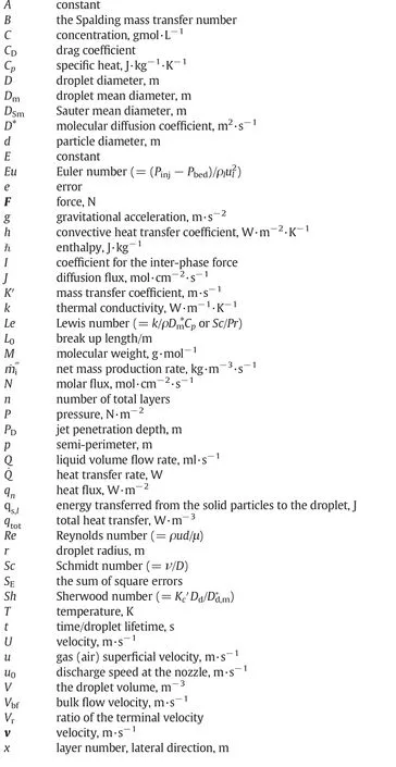
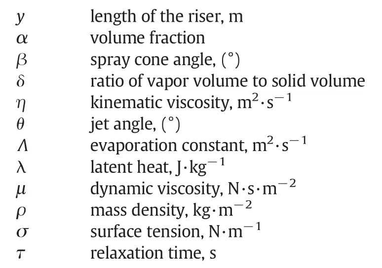
Nomenclature
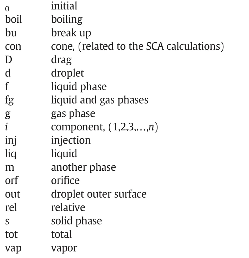
Superscript

Subscripts
[1]A.H.Lefebvre,Atomization and sprays,Hemisphere Pub.Corp.,New York,1989.
[2]C.Mirgain,C.Briens,M.D.Pozo,R.Loutaty,M.Bergougnou,Modeling of feed vaporization in fluid catalytic cracking,Ind.Eng.Chem.Res.39(2000)4392–4399.
[3]R.Wang,C.Li,X.He,B.Chen,A novelclose-loop strategy for integrating process operations of fluidized catalytic cracking unit with production planning optimization,Chin.J.Chem.Eng.16(2008)909–915.
[4]C.Liu,Y.Guo,Mechanisms for particle clustering in upward gas–solid flows,Chin.J.Chem.Eng.14(2006)141–148.
[5]S.Wang,H.Lu,J.Gao,C.Xu,D.Sun,Numerical predication of cracking reaction of particle clusters in fluid catalytic cracking riser reactors,Chin.J.Chem.Eng.16(2008)670–678.
[6]E.B.Babinsky,P.E.Sojka,Modeling drop size distributions,Prog.Energy Combust.Sci.28(2002)303–329.
[7]R.W.Sellens,T.A.Brzustowski,A prediction of the drop size distribution in a spray from first principles,At.Spray Technol.(1985)89–102.
[8]X.Li,R.S.Tankin,Droplet size distribution:A derivation of a Nukiyama–Tanasawa type distribution function,Combust.Sci.Technol.56(1987)65–76.
[9]X.Li,L.P.Chin,Comparison between experiments and predictions based on maximum entropy for sprays from a pressure atomizer,Combust.Flame 86(1991)73–89.
[10]G.W.M.Vander,H.Vermeer,Prediction of drop size distributions in sprays using the maximum entropy formalism:The effect ofsatellite formation,Int.J.Multiphase Flow 20(1994)363–381.
[11]V.Semiao,P.Andrade,M.D.G.Carvalho,Spray characterization:Numerical prediction of Sauter mean diameter and droplet size distribution,Fuel 75(1996)1707–1714.
[12]M.M.El-kotb,Fuel atomization for spray modeling,Prog.Energy Combust.Sci.8(1982)61–91.
[13]N.Dombrowski,W.R.Johns,The aerodynamic instability and disintegration of viscous liquid sheets,Chem.Eng.Sci.18(1963)203–214.
[14]C.Dumouchel,S.Boyaval,Use of the maximum entropy formalism to determine drop size distribution characteristics,Part.Part.Syst.Charact.16(1999)177–184.
[15]G.Aguilar,B.Majaron,W.Verkruysse,Y.Zhou,J.S.Nelson,E.J.Lavernia,Theoretical and experimental analysis of droplet diameter,temperature and evaporation rate evaluation in cryogenic spray,Int.J.Heat Mass Transf.44(2001)3201–3211.
[16]H.Sun,B.Bai,J.Yan,H.Zhang,Single-jet spray mixing with a con fined cross-flow,Chin.J.Chem.Eng.21(2013)14–24.
[17]J.Li,S.Huang,X.Wang,Numerical study of steam-water separators with wave-type vanes,Chin.J.Chem.Eng.15(2007)492–498.
[18]Y.R.Sivathanu,J.P.Gore,A discrete probability function method for the equation of radiative transfer,J.Quant.Spectrosc.Radiat.Transf.49(1993)269–280.
[19]S.D.Sovani,P.E.Sojka,Y.R.Sivathanu,Prediction of drop size distributions from first principles:Joint PDF effects,Atomization Sprays 10(2000)587–602.
[20]S.D.Sovani,P.E.Sojka,Y.R.Sivathanu,Prediction of drop size distributions from first principles:The in fluence of fluctuations in relative velocity and liquid physical properties,Atomization Sprays 9(1999)133–152.
[21]T.Li,K.Pougatch,M.Salcudean,D.Grecov,Numerical modeling of an evaporative spray in a riser,Powder Technol.201(2010)213–229.
[22]V.A.Iyer,J.Abraham,V.Magi,Exploring injected droplet size effects on steady liquid penetration in a Diesel spray with a two-fluid model,Int.J.Heat Mass Transf.45(2002)519–531.
[23]J.A.Bassard,R.E.Peck,Dropletsize distribution effects in spray combustion,Presented at the 26th Int.Symp.Combust.Inst.Napoli 1996,pp.1671–1677.
[24]J.Hayashi,J.Fukui,F.Akamatsu,Effects off uel drop size distribution on soot formation in spray flames formed in laminar counter flow,Proc.Combust.Inst.(2013)1562–1569.
[25]J.Hayashi,H.Watanabe,R.Kurose,F.Akamatsu,Effects of fueldroplet size on soot formation in spray flames formed in a laminar counter-flow,Combust.Flame 148(2011)2560–2569.
[26]P.Deepu,S.Basu,R.Kumar,Vaporization dynamics of functional droplets in a hot laminar air jet,Int.J.Heat Mass Transf.56(2013)69–79.
[27]K.Yokota,S.Matsuoka,An experimentalstudy offuelspray in a dieselengine,Trans.Jpn.Soc.Mech.Eng.43(1973)3455–3464.
[28]H.Hiroyasu,M.Arai,Fuelspray penetration and spray angle in dieselengines,Trans.Jpn.Soc.Mech.Eng.21(1980)5–11.
[29]T.R.Ohrn,D.W.Senser,A.H.Lefebvre,Geometrical effects on spray cone angle for plain-orifice atomizers,At.Sprays 1(1991)137–154.
[30]A.H.Lefebvre,D.R.Ballal,Gas turbine combustion,Taylor&Francis Group,2010.
[31]D.S.J.Jones,P.P.Pujadó,Handbook of petroleum processing,Springer,Dordrecht,2006.
[32]I.S.Han,C.B.Chung,J.B.Riggs,Modeling of a fluidized catalytic cracking process,Comput.Chem.Eng.24(2000)1682–1687.
[33]N.Ashgriz,Handbook of atomization and sprays:Theory and applications,Springer,Dordrecht Heidelberg London,New York,2011.
[34]S.Kim,C.S.Lee,D.J.Lee,Modeling of binary dropletcollisions for application to interimpingement sprays,Int.J.Multiphase Flow 35(2009)533–549.
[35]P.J.O'Rourke,Collective drop effects on vaporizing liquid sprays(Ph.D.thesis)Mech.Aero.Eng.,Princeton University,USA,1981.
[36]Y.Behjat,S.Shahhosseini,M.M.Ahmadi,Modeling gas oilspray coalescence and vaporization in gas solid riser reactor,Int.Commun.Heat Mass Transfer 37(2010)935–943.
[37]V.Mathiesen,T.Solberg,B.H.Hjertager,An experimental and computationalstudy of multiphase flow behavior in a circulating fluidized bed,Int.J.Multiphase Flow 26(2000)387–418.
[38]S.Bhowmick,N.A.Baveja,C.P.Shringi,K.T.Shenoy,S.K.Ghosh,Pressure fluctuations in a liquid-sprayed gas fluidized bed,ChemicalEngineering Division,Ind.Eng.Chem.Res.53(2014)12631–12638.
[39]A.H.Lefebvre,Fuelinjection,Gas turbine combustion,McGraw-Hill Book Co.,1983(10th chapter).
[40]K.Sridhara,Gas making in the dilution zone of a combustions chamber,Technical Report(TN-30).,National Aeronautical Laboratory,Bangalore,India,1970.
[41]J.S.Buchanan,Analysis of heating and vaporization of feed droplets in fluidized catalytic cracking risers,Ind.Eng.Chem.Res.33(1994)3104–3111.
[42]H.Ali,S.Rohani,Dynamic modeling and simulation of a riser-type fluid catalytic cracking unit,Chem.Eng.Technol.20(1997)118–130.
[43]W.E.Ranz,W.R.Marshall,Evaporation from drops—Part I,Chem.Eng.Prog.48(1952)141–146.
[44]W.E.Ranz,W.R.Marshall,Evaporation from drops—Part II,Chem.Eng.Prog.48(1952)173–180.
[45]CFX_Mgn.,CFX-5 solver and solver manager,1999 5.
[46]D.J.Gunn,Transfer ofheat or mass to particles in fixed and fluidized beds,Int.J.Heat Mass Transf.21(1978)467–476.
[47]Principalof combustion,John Wiley&Sons,Inc.,Hoboken,New Jersey,2005.
[48]C.Li,J.Li,Laminar forced convection heat and mass transfer of humid air across a verticalplate with condensation,Chin.J.Chem.Eng.19(2011)944–954.
[49]P.Eisenklam,S.A.Arunachlaman,J.A.Weston,Evaporation rates and drag resistances of burning drops,11th Int.Symp.on Combustion,Pittsburgh 1967,pp.715–728.
[50]J.Garside,M.R.Al-Dibouni,Velocity–voidage relationships for fluidization and sedimentation,Ind.Eng.Chem.Process Des.Dev.16(1977)206–214.
[51]Fluent,Modeling multiphase flows,FLUENT 6.3 user's guide.,Fluent Inc.,Lebanon,2003.
[52]A.Saboni,S.Alexandrova,Numericalstudy of the drag on a fluid sphere,AIChE J.48(2002)2992–2994.
[53]M.Syamlal,T.J.O'Brien,Computer simulation of bubbles in a fluidized bed,AIChE Symp.Ser.85(1989)22–31.
[54]A.L.Yarin,Drop impact dynamics,splashing,spreading,receding,bouncing,Annu.Rev.Fluid Mech.38(2006)159–192.
[55]V.K.Pareek,A.A.Adesina,A.Srivastava,R.Sharma,Modeling of a non-isothermal FCC riser,Chem.Eng.J.92(2003)101–109.
[56]S.V.Nayak,S.L.Joshi,V.V.Ranade,Modeling ofvaporization and cracking of liquid oil injected in a gas–solid riser,Chem.Eng.Sci.60(2005)6050–6067.
[57]R.S.Miller,K.Harstad,J.Bellan,Evaluation ofequilibrium and non-equilibrium evaporation models for many droplet gas liquid flow simulation,Int.J.Multiphase Flow 24(1998)1025–1055.
[58]S.R.Turns,An introduction to combustion:Concepts and applications,McGraw-Hill,2000.
[59]J.Li,A.H.Lefebvre,J.R.Rollbuhler,Effervescent atomizers for smallgas turbines,Am.Soc.Mech.Eng.94(1994)1–6.
[60]M.S.El-Shanawany,A.H.Lefebvre,Airblast atomization:The effect oflinear scale on mean drop size,J.Energy(1980)184–189.
[61]G.L.Borman,K.W.Ragland,Combustion engineering,McGraw-Hill,1998.
[62]G.E.Lorenzetto,A.H.Lefebvre,Measurements of drop size on a plain-jet airblast atomizer,AIAA J.15(1977)1006–1010.
[63]A.K.Jasuja,Atomization of crude and residualfueloils,J.Eng.Gas Turbines Power 101(1979)250–258.
[64]M.M.El-kotb,Fuel atomization for spray modeling,Prog.Energy Combust.Sci.8(1982)61–91.
[65]V.G.Levich,Physicochemical hydrodynamics,2nd ed.Prentice-Hall,Englewood Cliffs,NJ,1962 639–650.
[66]DuPont,Thermodynamic properties of DuPont™ Freon®22(R-22)refrigerant,The miracles of science™20112011.
[67]S.D.Heister,Plain orifice spray nozzles,Handbook of atomization and sprays.,Springer,2011 625–645.
[68]M.R.Spiegel,Mathematicalhandbook of formulas and tables,Schaum's outline series.,McGraw-Hill Inc.,New York,1968.
[69]X.Wang,Z.Chao,A.Rajesh,Numericalsimulation ofevaporating spray jets in concurrent gas–solids pipe flows,Powder Technol.140(1)(2004)56–67.
[70]J. Jaccard, R. Turrisi, C.K.Wan, Interaction effects in multiple regression—Quantitative applications in the social sciences,Sage Pub.Inc.,Int.Prof.Pub.,New Delhi,1990.
[71]J.G.Orme,T.C.Orme,Multiple regression with discrete dependent variables,Oxf.Univ.Press Inc.,New York,2009.
[72]H.Yanagii,Multivariate analysis handbook,Gendai Sugakusha,Tokyo,1986.
 Chinese Journal of Chemical Engineering2016年2期
- Chinese Journal of Chemical Engineering的其它文章
- Photorheologically reversible micelle composed ofpolymerizable cationic surfactant and 4-phenylazo benzoic acid☆
- CFD based extraction column design—Chances and challenges
- Analysis of drop deformation dynamics in turbulent flow
- Review on current advances,future challenges and consideration issues for post-combustion CO2 capture using amine-based absorbents☆
- Experimental study on the effects of big particles physical characteristics on the hydraulic transport inside a horizontal pipe
- Relationship between breakthrough curve and adsorption isotherm of Ca(II)imprinted chitosan microspheres for metaladsorption☆
