
Three Dimension Electromagnetic-Thermal-Mechanical Coupling Finite Element Model for High Frequency Induction Mobile Heating Formation of Steel Plate
2016-05-16 02:42:06WANGZhixingWANGShuiLIUZiyng
船舶力学 2016年3期
,,WANG Zhi-xing,,WANG Shui,LIU Zi-yng
(a.School of Mechantronics&Vehicle Engineering;b.Chongqing Engineering Research Center for Special Ship Digital Design and Manufacturing,Chongqing Jiaotong University,Chongqing 400074,China)
Three Dimension Electromagnetic-Thermal-Mechanical Coupling Finite Element Model for High Frequency Induction Mobile Heating Formation of Steel Plate
ZHANG Ji-xianga,b,XU Yua,WANG Zhi-xianga,b,ZHONG Lia,WANG Shuaia,LIU Zi-yanga
(a.School of Mechantronics&Vehicle Engineering;b.Chongqing Engineering Research Center for Special Ship Digital Design and Manufacturing,Chongqing Jiaotong University,Chongqing 400074,China)
An electromagnetic-thermal-stress coupling finite element model of multi physics fields is established using the ANSYS-APDL language,in which a coil unit selection method is adopted to realize the mobile induction heating source,a physical environment indirect coupling method to realize electromagnetic thermal coupling,and an equivalent substitution indirect coupling method to realize thermal stress coupling.The high frequency induction heating process of the steel plate is simulated using this model,and the main conclusions were as follows:Firstly,in the intial stage and termination stage apparent end effect of heating temperature,internal stress and bending deformation are observed.Secondly,in stable heating stage,the heating zone below coil has the highest temperature,and in the thickness direction and width direction pointing to the heating area front there are large temperature gradient and stress gradient.And thirdly,on the surface of the steel plate,the compressive stress of heating area and front heat affected zone reaches high temperature yield strength of Q345 steel,so a permanent compression plastic deformation is acquired,then the plate will bend into a concave after cooling.The increase of heating power can make steel plate heating temperature increase,the temperature gradient increases in the direction of plate width,and decreases in the direction of thickness,which will prompt larger bending deformation.The above simulation results agree with those of the experimental measurement.
thermal stress forming;frequency induction heating;FEA;coupling model
0 Introduction
Thermal stress forming is a kind of metal forming method,which depends on the thermal stress caused by uneven distribution of internal temperature field to drive the steel plate bending deformation[1-2].There are two conventional methods for large ship steel sheet thermal stress forming.One is oxy-acetylene flame heating forming,the other is the laser heating forming. The oxy-acetylene flame heating forming is the most widely method in ship manufacturing.However,this method has low precision,poor stability,and is difficult to realize production automation[3].Laser heating is easier to control the heating region and the heating power[4],but the equipment fee is expensive and the heating power is weak that is not able to meet the requirement of the thick steel plate forming.Because of the disadvantages of the oxy-acetylene torch heating and laser heating,the high-frequency induction heating was proposed.
A lot of achievements have been obtained in study of high-frequency induction heating,especially the outstanding contribution of finite element analysis[5-24].The finite element model of ship plate static induction heating elastic-plastic deformation were simulated and analyzed by Japanese Ishikawajima-Harima Heavy Industries I.Neki,Jun-ichiro Ogawa et al in 1993[5]. The idea of plate deformation prediction with the computer analysis technology is proposed by Jang Chang-Doo in Korea University in 2002[6].Now,three kinds of the finite element simulation model built for high frequency induction heating plate forming are as follows:
(1)Steel plate thermal elastic-plastic deformation of static induction heating was analysed in Ref.[5],and the simulated results were compared with the experimental results.A two-dimensional electromagnetic-thermal-mechanical coupling static finite element model was established in Refs.[1-2].A two-dimensional static finite element model with weight constraints was established in Refs.[13-14],As shown in Fig.1.
(2)A heat source direct loading type three-dimensional mobile finite element model was established in Ref.[15-16].Without electromagnetic-thermal coupling calculation,a fitting characteristic function of the measured heat flux distribution was loaded into the surface of steel plate as the heat source in the model,as shown in Figs.2-3.Another similar finite element model was built in Ref.[7],which heat source form is similar to the welding heat source model.
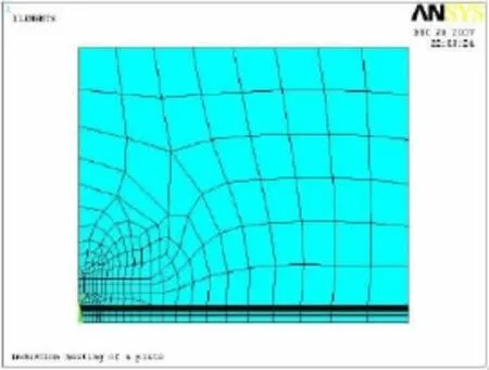
Fig.1 Two dimensional static model
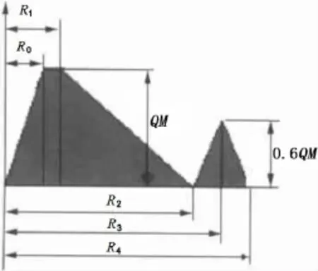
Fig.2 The heat source characteristic function
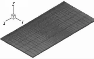
Fig.3 Temperature field finite element model
(3)A three-dimensional static finite element model was established in Refs.[17-20],as shown in Fig.4,in which three dimension electromagnetic-thermal-mechanical coupling was realized,while its heat source is stationary,so the model can not simulate mobile heating.
Based on the above problem,this paper uses APDL language to build an electromagnetic-thermal-stress coupled multi-physics finite element model with three-dimensional mobile source in order to realize the simulation of ship moving induction heating deforming.
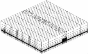
Fig.4 Three dimensional static finite element model
1 FEM modeling
1.1 Model simplification
The sample of 480 mm long,240 mm wide,10 mm thick Q345 ship steel plate,with a diameter of 6 mm,wall thickness of 1mm tube wound into a circular coil with 40 mm.Moving the heating coil in the middle of the steel sheet,the spacing between the upper surface and the lower surface of the steel sheet coil is 2 mm,as shown in Fig.5(a).To facilitate the finite element modeling,based on the principle of equal area,circular coil will be reduced to a thickness of 6mm,length and width of 34 mm×34 mm cube coil.The simplified excitation current direction of rectangular coil section and the excitation current direction of circle coil section were consistent.Since the model has a high degree of symmetry,half of the sample can be taken as the research object,as shown in Fig.5(b).
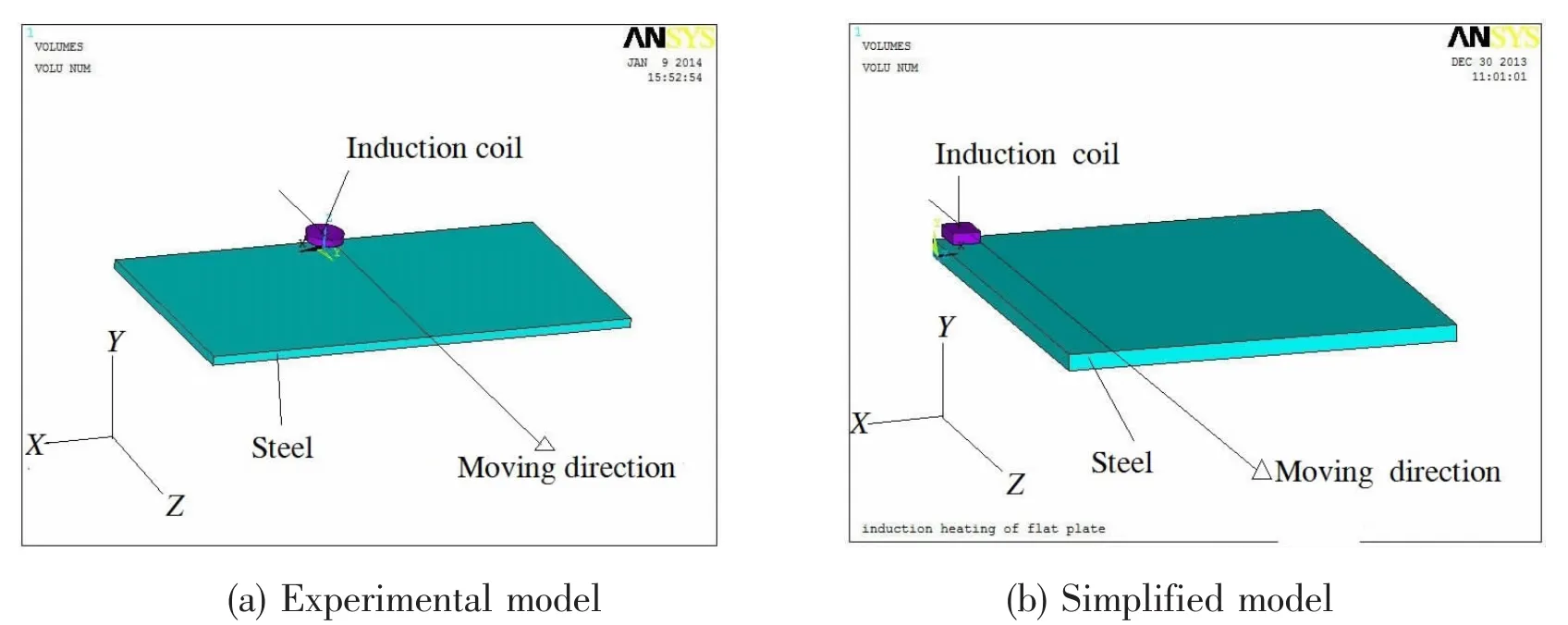
Fig.5 High frequency induction heating model
1.2 FEM element type
Selection SOLID117 20-node hexahedral magnetic vector unit calculates the moving harmonic magnetic field,SOLID70 8-node hexahedral thermal unit calculates the temperature field,SOLID45 eight-node hexahedral structure unit calculates structural stress and strain fields(see Fig.6).
1.3 Realization of mobile heating

Fig.6 Three-dimensional finite element model
In this model,the moving heating of the induc-tion coil through the following calculation process to achieve:
(1)Create a 310 mm×34 mm×6 mm rectangular on the coil moving path.Both ends of the rectangular extended 34 mm,as shown in Fig.7(a);
(2)The rectangular along Z axis direction is evenly divided into 155 small cuboids,each rectangular with dimensions of 2 mm×34mm×6mm,and respectively to 1,2,...155 code;
(3)Let Δt=tC/155,where,tC=310 mm/v,v is the moving speed of the coil;
(4)At the time t=0 s,let i=0,select the small rectangular of number 1,2…,17.A total of 17 small rectangular form a cube(Fig.7(b)below).The electric current density will be loaded into the cube,continuous time after Δt,calculating the excitation current of the steel plate and the temperature field,stress field and strain field produced by the excitation current;
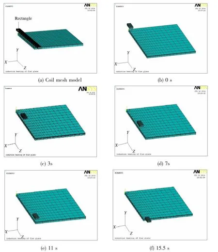
Fig.7 The selection of coil unit
(5)Let t=t+Δt,i=i+1,select the small rectangular of number 1,2…,17.A total of 17 small rectangular form a cube(Fig.7(c)below),The electric current density will be loaded into the cube twice,continuous time after Δt,calculating the excitation current of the steel plate and the temperature field,stress field and strain field produced by the excitation current;
(6)Repeat step(5),until the end of i+17=155(Fig.7(f)).
1.4 Electromagnetic-thermal coupling method
Using physical environment indirect coupling method to achieve electromagnetic-coupled heat,the process is as follows:
(1)Firstly,the physical environment of electromagnetic field and the temperature field was established;
(2)Create a 310 mm×34 mm×6 mm rectangular on the coil moving path.Both ends of the rectangular extend 34 mm;
(3)The rectangular along Z axis direction is evenly divided into 155 small cuboids,each rectangular with dimensions of 2 mm×34 mm×6 mm,and respectively to 1,2,…,155 code;
(4)Let Δt=tC/155,where,tC=310 mm/v,v is the moving speed of the coil;
(5)When t=5 s,reading the electromagnetic environment,make j=0,Select the cube coil composed by a small rectangular numbered 1,2…,17,and then current density was loaded into it;
(6)Duration Δt,calculating the magnetic field so as to obtain the heat generation rate of steel plate,then calculate the temperature field by the heat generation rate of steel plate;
(7)Let t=t+Δt,updating electromagnetic parameters based on the calculated temperature field,let j=j+1,select the cube coil composed by a small rectangular numbered j+1,j+2…, j+17 twice,and then current density was loaded into it;
(8)Repeat steps(6)-(7),until the end of i+17=155;
(9)Restart thermal analysis,to begin the cooling process temperature field analysis;
(10)Let t=t+Δt1,j=j+1,Δt1=1 s is the cooling time step;
(11)When t=15.5 s,the heating transient temperature field file during 15.5 s is read,cooling analysis began,until the end of t=900 s,j=1 055.
1.5 Thermal-mechanical coupling method
Using the equivalents indirect coupling methods to achieve thermal-stress coupling:
(1)Delete all the thermal analysis of the load step;
(2)For thermal stress calculated by equivalent unit SOLID45 thermal structure replacing solid element SOLID70;
(3)Start the static analysis of structural stress field;
(4)From t=0 s,j=1 starts to t=15.5 s,j=155,reads the heating process temperature field RST file,enter the entire steel instantaneous results of the last sub-step of every step of the whole process as the initial stress and strain of data;
(5)From t=15.5 s,j=1 starts to t=900 s,j=1 055,reads the heating process temperature field RST file,enter the entire steel instantaneous results of the last sub-step of every step ofthe whole process as the initial stress and strain of data;
(6)Using the above data to calculate the stress field changes until the end of t=900 s;
(7)Entire heat-stress coupling process is complete,save DEFORM file.
1.6 Boundary conditions,loads and constraints
(1)The gravity load
Due to steel itself has a certain influence on the gravity bending steel plates,steel plates need to load their own gravity loads.In this paper,by applying the acceleration of gravity on all nodes to achieve their own gravity loads.
(2)The displacement constraints
Symmetry plane constraints is imposed on the plane of X=0,For restraint the UY freedom of nodes on the right end face and the bottom plate personally lines,shown in Fig.8.
(3)Cooling boundary condition
The initial temperature was set at 10℃,applying the thermal boundary conditions on the surface of steel plate up and down for heat transfer coefficient of 15 W/(m2℃).And applying the thermal boundary conditions on the right side surface before and after for heat transfer coefficient of 10(m2℃).
1.7 Material model
Plate materials is Q345 steel,the thermal physical parameters are conductivity K,magnetic permeability μ and elastic modulus E,yield strength σs,shear modulus G as shown in Tab.1,μ of the Copper coils and the air permeability is 1 h/m.
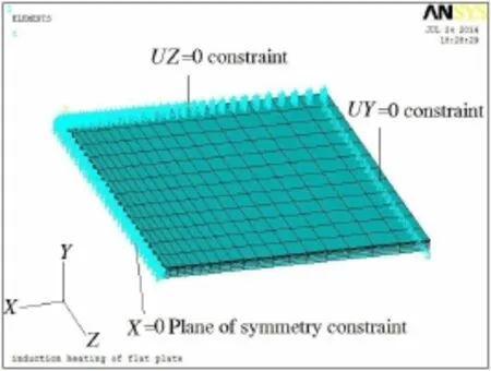
Fig.8 The displacement constraint model
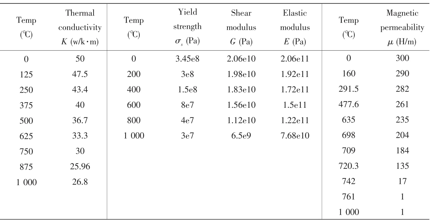
Tab.1 Q345 steel plate thermal physical parameters
1.8 Program algorithm
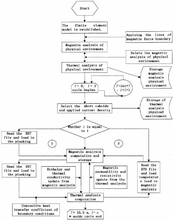
Fig.9 Program algorithm of the model
2 Research program
The research of Q345 steel plate bending angle and radius of curvature on the establishment model of steel plate in the case of exciting current frequency=20 kHz,heating time= 12 s,moving coil rate=l/t=0.02 m/s,research plan as shown in Tab.2.

Tab.2 Research scheme
The temperature fields of steel plate heated by 25kW power are shown in Fig.10(a1-a10).During heating,the temperature field is unstable,that is to say,apparent end effect with higher heating temperature is shown in the intial stage and termination stage,and especially in the termination stage,it is the most significant with the highest heating temperature of 1 150℃, higher than the temperature of 645℃ in the intermediate heating stage.The temperature field of steady heating period is similar to welding spindle temperature field,and the temperature gradients in thickness direction and width direction pointing to front of the heating area are verylarge,whether much smaller in other direction.During cooling,the isothermal lines possess more and more wide range,and the temperature gradient is getting smaller.The temperature fields and their evolution above are consistent with the measured results.
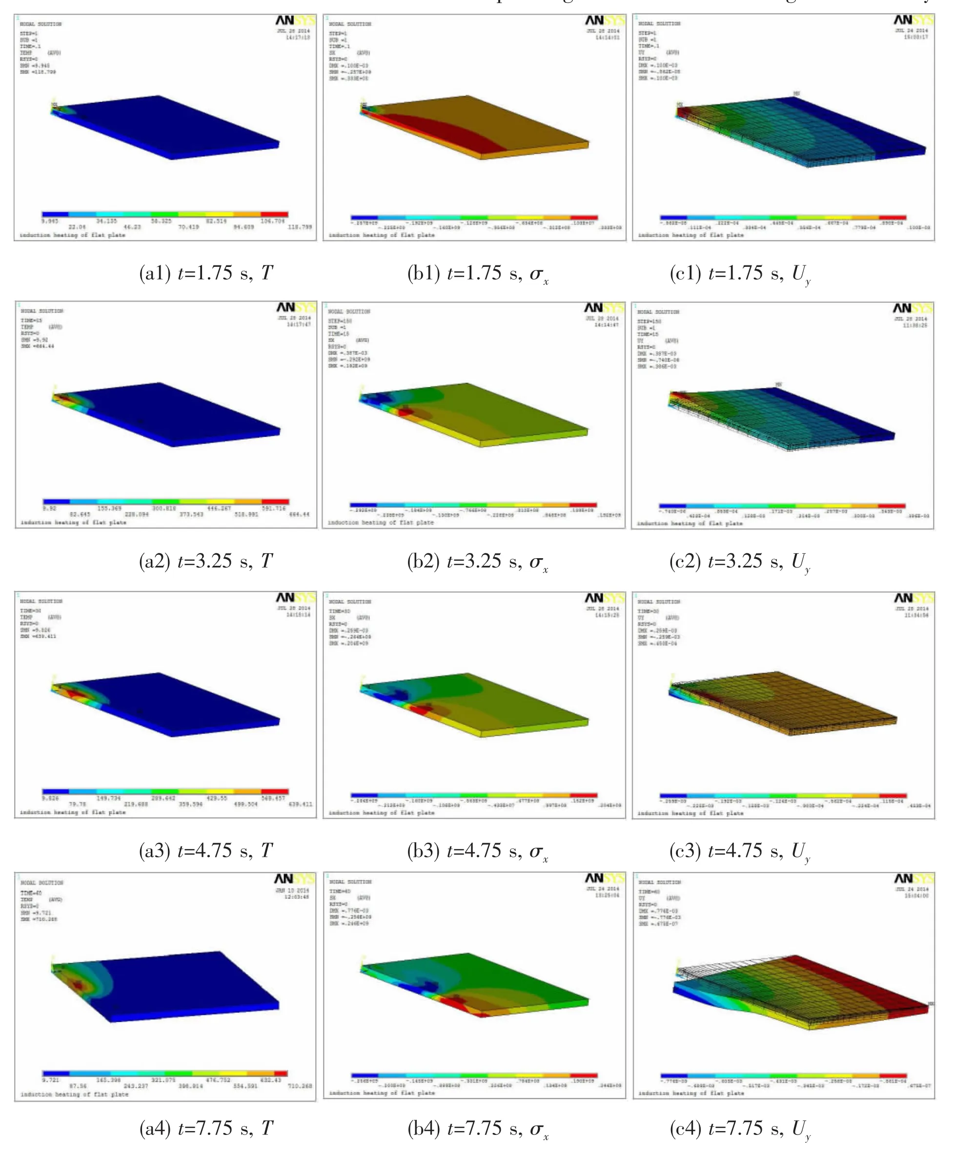
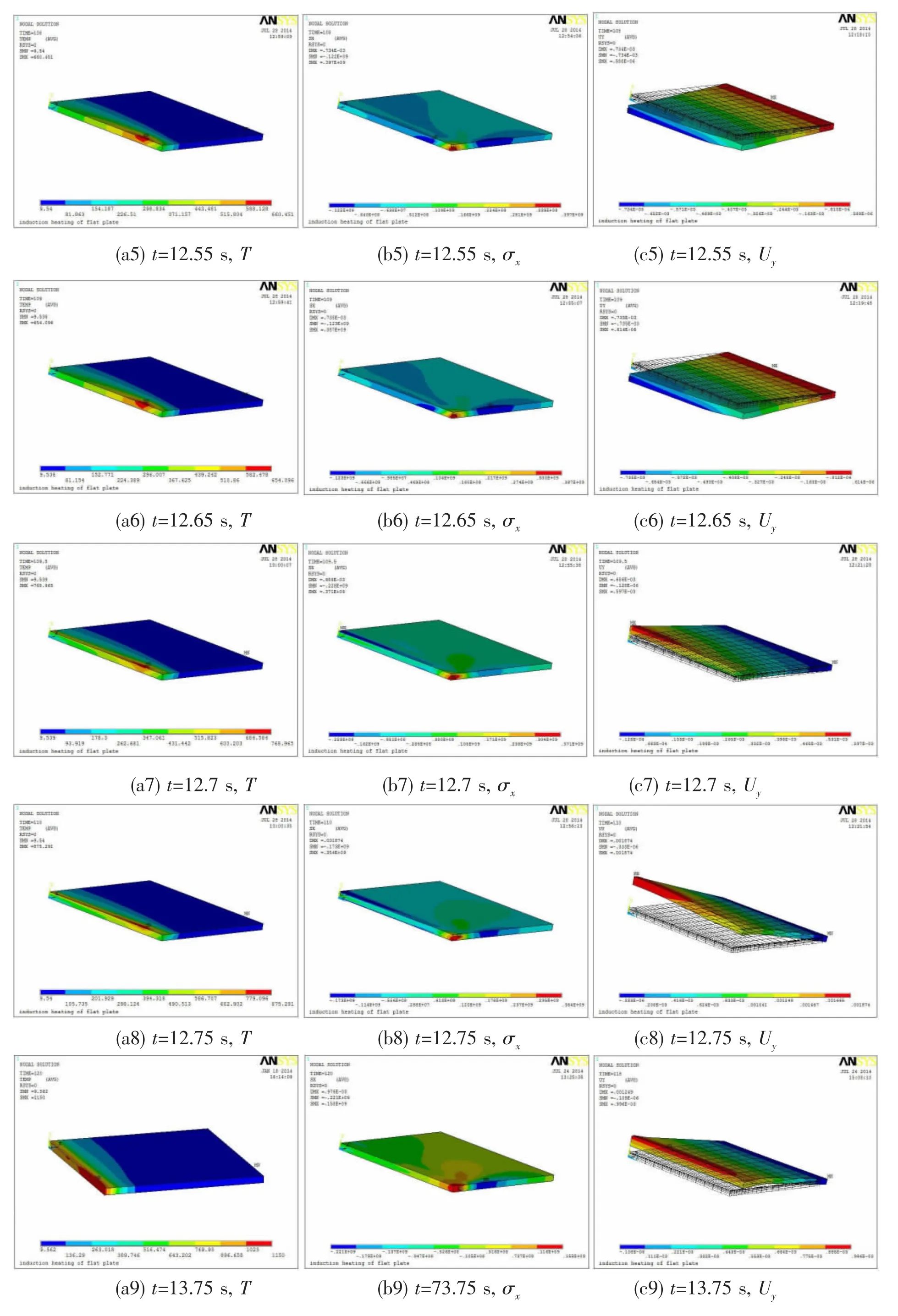
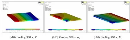
Fig.10 Temperature field,stress field and deformation field during heating and cooling of the steel model (a1-a10)Temperature field,(b1-b10)Stress field,(c1-c10)Deformation field
The stress fields of steel plate heated by 25 kW power are shown in Fig.10(b1-b10).It can be seen from the Fig.10(b2-b4)that there is a great stress gradient in the Y direction of heating area below the coil.In the stable intermediate heating stage,the compressive stress appears in heating and heated areas where could not expand freely due to the constraint of unheated area,and the maximum compressive stress is not in the zone directly below the coil,but in the heat affected zone where is in front of the heating zone and on the surface of the sheet metal.The compressive stress in the zone below coil is between 10-100 MPa,which is equal to the yield strength of Q345 at the heating temperatures in this zone,while the maximum compressive stress is between 250-300 MPa,equal to the yield strength equal to the plate yield stress at the heating temperatures in that zone,as shown in Fig.10(b4).The tensile stress appears in the unheated area dragged by the heating area,and the maximum tensile stress is far away in front of the heating area.It is also seen that apparent end effect with higher tensile stress appears in the termination stage.The residual stress field of steel plate after cooling 900 s is shown in Fig.10(b10).It is shown from the figure that there is obvious internal stress in the steel plate,while the stress gradient is small in thickness direction.The maximum compressive stress of 248 MPa is at the end of heating line,while the maximum tensile stress of 82.1 MPa is in the middle of the heating line.
The deformation fields in Y direction are shown in Fig.10(c1-c10).In the intial stage,the deformation in heating area is only elastic because the compressive stress is only 257 MPa, less than the yield strength of 300 MPa at the temperature of 120℃,as shown in Fig.10(c1). When stable heating,the highest temperature on the surface is above 600℃,and the compressive stress in heating area and the front end heat affected area reached the high temperature yield strength,so the steel plate produces permanent compression plastic deformation,while now the heating area is still upward bended due to heat expansion.With the moving of heat source,the heated area is downward bended,as shown in Fig.10(c2-c6).When the heat sourceclose to the end of heating line,the tensile stress area is gradually disappearing(shown in Fig.12(b7)),so the constraint force for heat expansion is also disappearing,which prompts the whole heated area to be upward bended,and finally the plate will be downward bended after cooling.
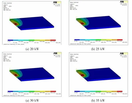
Fig.11 Steel plate temperature field nephogram
The temperature fields of continuous heating 8.75 s with heating power of 20 kW,25 kW, 30 kW,35 kW are shown in Fig.11.It can be seen that the isothermal curves are with similar shape in these four temperature fields,and with the increase of power,the heating temperature is rising,with gradually increasing temperature gradient in the width direction and reducing temperature gradient in the thickness direction.The above temperature fields are consistent with the measured results.
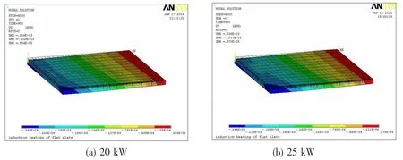

Fig.12 Steel plate deformation nephogram of Y direction
The Y direction deformation fields after cooling for 900 s are shown in Fig.12.It can be seen that the bigger the heating power,the greater the bending deformation, and along the heating line the deformation is uneven,the biggest deformation appeares on the line end,which calls end effect of deformation,and with the increase of heating power end effect is more and more obvious.
The results of experiment and simulation under different powers are shown in Fig.13.As can be seen,the bending angle increases approximately linearly with the heating power,and the results of simulation are consistent with experimental results,except under the low power(20 kW)heating condition.The error under the low power heating condition is caused by the imprecise low temperature heat dissipation conditions in the simulation analysis.
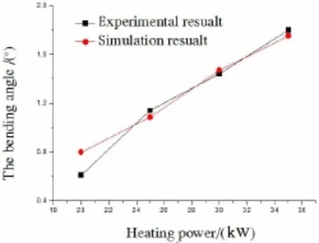
Fig.13 Bending angle of experiment and simulation
4 Conclusions
(1)An electromagnetic-thermal-stress coupling finite element model of multi physics fields is established using the ANSYS-APDL language,in which a coil unit selection method is adopted to realize the mobile induction heating source,a physical environment indirect coupling method to realize electromagnetic thermal coupling,and an equivalent substitution indirect coupling method to realize thermal stress coupling.The induction heating forming of steel plate is simulated using the model,and the simulation results agree with those of experiment.
(2)During the heating,the temperature field in steel plate is not stable,and at the start and end time,temperature,stress and deformation appear obvious end effect.In stable heating stage,in the plate thickness direction and the plate width direction ahead of the heating zonethere is great temperature gradient.
(3)In stable heating stage,there is compressive stress in the heating area.The maximum compressive stress is not in high temperature area right under the coil,but in the heat affected zone in the front of heating area.The maximum tensile stress is far in the front of the heat affected zone.There is a large stress gradient in the thickness direction of heating zone,and there is one in the width direction after cooling.
(4)In the stable heating stage,pressure stress reaches the yield stress of high temperature in the heating area of metal plate surface and the front heat affected zone,so a permanent plastic compression deformation occurs and a concave bending deformation appears in the heating area after cooling.
(5)With the increase of heating power,the heating temperature rises,with the isotherm range expanses and the temperature gradient in the plate width direction enlarges,so the steel plate bending deformation increases.Along the whole heating line the deformation is uneven, that is to say,there is an obvious deformation end effect appears in the plate,and the largest deformation is at the end of heating line.Along with the increase of heating power,the end effect is more and more obvious.The above simulation results agree with those of the experimental measurement.
[1]Fan Ping,Chen Minghe.Experimental study of high frequency induction thermal stress forming technology of plate[J]. Forginf&Stamping Technology,2008,33(5):38-39.
[2]Fan Ping,Chen Minghe,Zhou Zhaofeng.Steel plate without technology of thermal stress forming die forming[J].New Technology&New Process,2007(11):62-64.
[3]Zhou Hong,Li Gan,Zhu Hongjuan.Effects of ship plate boundary conditions on the high frequency induction plate bending[J].Ship&Ocean Engineering,2009,10,38(5):17-19.
[4]Guan Yanjin,Ji Zhong,Sun Sheng.The laser induced thermal stress forming technology and its application[J].Aeronautical Manufacturing Technology,1999(4):30-32.
[5]Yoshihiko T,Morinobu I,Nagahara S.Automated line heating for plate forming by IHI-ALPHA system and its application to construction of actual vessels system outline and application record to date[J].Journal of the Society of Naval Architects of Japan,2004(193):85-95.
[6]Jang Chang-Doo,Kim Ho-Kyung,Ha Yun-Sok(Department of Naval Architecture and Engineering,Seoul National University,Seoul,Korea).Prediction of plate bending by high-frequency induction heating[J].Journal of Ship Production, 2002,1(18):226-236.
[7]Lee Soon-Bok,Kim Yun-Jae.An electromagnetic and thermo-mechanical analysis of high frequency induction heating for steel plate bending[J].Key Engineering Materials,2006,326-328:1283-1286.
[8]Nguyen Truong-Thinh,Yang Young-Soo,Bae Kang-Yul,Choi Sung-Nam.Prediction of deformations of steel plate by artificial neural network in forming process with induction heating[J].Journal of Mechanical Science and Technology,2009, 23(4):1211-1221.
[9]Chen J,Qi Y,Shi Y,Bi Z.An analytical model to predict bending angles in high-frequency induction heat forming[J].Proceedings of the Institution of Mechanical Engineers,Part C:Journal of Mechanical Engineering Science,2010,224(3): 655-660.
[10]Lee Kwang Seok,Eom Deuk Ha,Lee Jung-Hwan.Deformation behavior of SS400 thick plate by high-frequency-induction-heating-based line heating[J].Metals and Materials International,2013,19(2):315-328.
[11]Jeong Chan-Man,Yang Young-Soo,Bae Kang-Yul,Hyun Chung-Min.Prediction of deformation of steel plate with forced displacement and initial curvature in a forming process with high frequency induction heating[J].International Journal of Precision Engineering and Manufacturing,2013,14(5):785-790.
[12]Lee Kwang Seok,Hwang Byoungchul.An approach to triangular induction heating in final precision forming of thick steel plates[J].Journal of Materials Processing Technology,2014,214(4):1008-1017.
[13]Zhang Jixiang,An Guoyin,Li Zhengjun,Wang Zhixiang.Free bending of ship plate of different thinckness on high-frequency induction[J].Journal of Chongqing Jiaotong University(Natural Science),2011,31(4):900-904.
[14]An Guoyin,Zhang Jixiang,Li Zhengjun,Wang Zhixiang.Study of deformation law of key points on high-frequency induction heating for ship plate[J].Ship Engineering,2013,35(5):87-89.
[15]Luo Yu,Jiang Xiaoling,Deng Dean.Influence of mechanical properties of materials on high frequency inducting plate bending[J].Material Engineering,2005(8):35-36.
[16]Shuai Kegang,Luo Yu.Finite element molding temperature field of high frequency induction heating plate bending analysis[J].Boiler Technology,2004,35(3):53-54.
[17]Zhang Xuebiao,Yang Yulong,Liu Yujun.The numerical analysis of temperature field during moveable induction heating of steel plate[J].Journal of Ship Production and Design,2012,28(2):73-81.
[18]Zhang Xuebiao,Yang Yulong,Hu Xuefeng,Ji Zhuosang.Experimental analysis and numerical simulation of induction heat forming of steel plate[J].Journal of Harbin Engineering University,2009,30(3):239-240.
[19]Zhang Xuebiao,Yang Yulong,Liu Yujun,Ji Zhuosang,Deng Yanping.Numerical analysis of high frequency induction heating process of steel plate bending process[J].Shipbuilding of China,2011,52(2):108-116.
[20]Zhang Xuebiao,Yang Yulong,Liu Yujun.Analysis of electromagnetic thermal coupling field of steel plate of high frequency induction heating process[J].Journal of Dalian University of Technology,2012,52(5):676-677.
[21]Zhou Hong,Jiang Zhiyong,Li Gan.Influence of high frequency induction processing parameters on plate bending[J].Ship Engineering,2011,33(1):57-58.
[22]Zhou Hong,Li Gan,Zhu Hongjuan.Effects of ship plate boundary conditions on high frequency induction plate bending [J].Transactions of the China Welding Institution,2010,31(11):101-102.
[23]Liu Shoufa,Fan Ping.Test bed design of high-frequency induction bending forming[J].Machinery Design&Manufacture, 2012(6):194-195.
[24]Chen Hao,Zhou Yueming,Hua Xueming.Temperature distribution insurface layer of workpiece duringinduction heating process and its mechanismanalysis[J].Heat Treatment of Metals,2011,36(2):66-68.
三维移动式钢板高频感应加热成形电磁—热—力全耦合有限元建模研究
张继祥a,b,徐 昱a,王智祥a,b,钟 厉a,王 帅a,刘紫阳a
(重庆交通大学a.机电与车辆工程学院;b.重庆市特种船舶数字化设计与制造工程技术研究中心,重庆400074)
文章基于ANSYS-APDL语言,建立了三维移动式钢板高频感应加热成形电磁—热—力多物理场耦合有限元模型,并使用线圈单元选取法实现了感应线圈热源模型的移动。文中采用此模型研究了Q345钢板在不同加热功率下的变形情况,得到如下结论:钢板加热时受热不均匀,加热区上下表面温差很大最后阶段出现端部效应;随着加热功率的增大,钢板表面瞬时最高温度也增大;加热过程中钢板最大压应力出现在上表面加热区前端,最大拉应力出现在钢板上表面加热区的前方;冷却后钢板最大压应力出现在加热线末端,最大拉应力出现在加热线中段区域;开始时加热区上翘,已加热区冷却下凹,当热源接近末端时,已加热变形区上翘,钢板经过冷却后,整体下凹;随着加热功率的增大,加热区域Y方向变形 Uy越大,钢板弯曲角度线性增大,曲率半径先减小后趋于定值;改进后模型的模拟结果与相同实验参数下的实验结果基本吻合,与传统模拟方法相比更接近实验结果。
热应力成形;高频感应加热;ANSYS;单元选取法;热源模型
O343.6
:A
张继祥(1971-),男,重庆交通大学机电与车辆工程学院教授,硕士生导师;
O343.6
A
10.3969/j.issn.1007-7294.2016.03.011
1007-7294(2016)03-0348-15
徐 昱(1989-),男,重庆交通大学机电与车辆工程学院硕士研究生;
王智祥(1955-),男,重庆交通大学航海学院教授,硕士生导师;
钟 厉(1965-),女,重庆交通大学机电与车辆工程学院教授,硕士生导师;
王 帅(1987-),男,重庆交通大学机电与车辆工程学院硕士研究生;
刘紫阳(1988-),男,重庆交通大学机电与车辆工程学院硕士研究生。
Received date:2015-12-04
Foundation item:Supported by Chongqing Foundation General and Frontier Research Plan Project(cstc2013jcyjA70015); Chongqing Municipal Education Commission Science and Technology Research Project(KJ080407)
Biography:ZHANG Ji-xiang(1971-),male,Ph.D.,professor,E-mail:jixiangzhang@163.com;
XU Yu(1989-),male,master graduate student.
猜你喜欢
学位与研究生教育(2022年10期)2022-12-06 03:09:18
中国机械工程(2022年22期)2022-11-25 08:24:30
中国机械工程(2022年7期)2022-04-20 03:25:38
煤气与热力(2021年3期)2021-06-09 06:16:20
中国机械工程(2019年17期)2019-09-19 07:43:32
中国机械工程(2018年4期)2018-03-06 05:34:58
电子制作(2017年19期)2017-02-02 07:08:31
中国诗歌(2016年1期)2016-11-26 15:13:15
新乡学院学报(2016年5期)2016-09-03 08:55:32
焊接(2015年8期)2015-07-18 10:59:13
- 船舶力学的其它文章
- Load-Compression Relationships of Bonded Rubber Ring
- Fatigue Reliability Analysis for the Manned Cabin of Deep Manned Submersibles Based on the Unified Fatigue Life Prediction Method
- An Engineering Method to Predict Fatigue Crack Propagation Life for Marine Structures
- Experimental Studies of Failure Behavior and Strength of H Beams with Stiffened Web Openings under Compression and Bending Loads
- A Combination Mooring System and Mooring Characteristics Study
- Numerical Prediction and Experimental Measurement on Truss Spar Motion and Mooring Tension in Regular Waves