The ballistic performance of the bombard Mons Meg
Ian LEWTAS,Rachael MCALISTER*,Adam WALLIS,Clive WOODLEY,Ian CULLIS
QinetiQ,Fort Halstead,Sevenoaks,Kent T N14 7BP,UK
The ballistic performance of the bombard Mons Meg
Ian LEWTAS,Rachael MCALISTER*,Adam WALLIS,Clive WOODLEY,Ian CULLIS
QinetiQ,Fort Halstead,Sevenoaks,Kent T N14 7BP,UK
The bombard Mons Meg,located in Edinburgh Castle,with a diameter of 19 inches (48 cm),was one of the largest calibre cannons ever built. Constructed in 1449 and presented to King James II of Scotland in 1454,Mons Meg was used in both military and ceremonial roles in Scotland until its barrel burst in 1680.This paper examines the history,internal,external and terminal ballistics of the cannon and its shot.The likely muzzle velocity was estimated by varying the propellant type and the cannon prof i le was investigated to identify weak spots in the design that may have led to its failure.Using the muzzle velocity calculated from the internal ballistics,simulations were performed with granite and sandstone shot for varying launch angle and ground temperature.The likely trajectory and range of the cannonballs are described.The internal and external ballistics informed the initial conditions of the terminal ballistic impact scenarios.The performance of the cannonball against both period and modern targets,in the form of a pseudo-castle wall and a monolithic concrete target,respectively,were simulated and are presented and discussed.
Analytical;Hydrocode;Muzzle velocity;Cannon barrel design;Trajectory;Castle brick target
1.Introduction
As one of the larger and well documented surviving medieval cannons,Mons Meg stands in pride of place at Edinburgh Castle and in its history (Fig.1).Constructed around 1449 in Mons,part of what is now modern day Belgium,at the request of Duke Philip the Good of Burgundy [2],the bombard was intended as a wedding present to King James II of Scotland,who,in 1457 married Duke Philips’great niece,Mary of Gueldres.
Customs records date Mons Meg’s f i rst arrival on Scottish shores around 1457 [3],seemingly f i rst taking place in battle at the siege of Roxburgh Castle in 1460,although this is not yet backed up in any way other than stories from the time [3].The earliest written record of her active role in service is during the 10 day bombardment of Norham Castle in 1513 [4]during which she is reported to have destroyed both the castle’s inner and outer wall.Her last use as a defensive weapon was during the Lang Siege 1571-73,after which she was only used for ceremonial duties.
One of the most famous stories about the bombard was the two month siege of Threave Castle by James II.The story goes that the f i rst cannonball f i red at the keep passed straight through the wall and severed the hand of Margaret Douglas as she was drinking inside.
Once retired from active military service she found a new role as a display piece at Edinburgh Castle.However,on 30 October 1680,to celebrate the visit of James Duke ofYork and Albany to Edinburgh,the barrel burst,effectively ending her operational life.
This paper investigates and discusses the internal,external and terminal ballistics of the cannon.The internal ballisticscalculates the likely muzzle velocity of the cannon and analyses the possible reasons for the barrel bursting.The external ballistics uses the results from the internal ballistics to analyse and predict the cannonball trajectory and likely f i nal velocity and impact angles.This is used to investigate its terminal performance against modern targets and period,castletype targets.
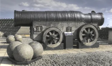
Fig.1.Mons Meg at Edinburgh Castle.Licensed under creative commons attribution-share alike 2.0 generic license [1].
2.The cannon
Mons Meg is constructed of wrought iron,sometimes called charcoal iron,a highly variable iron,both in chemical composition and slag content.However it is a very ductile metal and the levels of slag have made the iron extremely resistant to corrosion [5].It measures over 4 m in length,with a bore of 50 cm and weighing over 6000 kg [3],easily making it one of the largest (by calibre)stone f i ring cannons in history.
It is divided into 2 distinct parts,the powder chamber,and the barrel.The powder chamber measures 1.16 m in length,and varies from 0.59 to 0.53 m in diameter (Fig.2).It is likely that the powder chamber is constructed from one billet of iron which has been hammer-beaten on a mandrel to achieve the correct inner dimensions.The barrel measures 2.88 m in length externally,and varies from 0.63-0.75 m in diameter.It is constructed from 25 staves running the length of the barrel which are covered and held in place by 33 hoops.These would have been heated in a furnace and placed over the staves,as these cooled they would tighten to hold the barrel together and fasten the staves to the powder chamber.
Mons Meg f i red cannonballs roughly 490 mm in diameter. During Mons Meg’s operation lifetime in the 15th and 16th centuries,iron shot was not available and the cannonballs were made from local stone.There are records [7]which indicate both sandstone and granite shot was used to give mass ranges of 130-140 kg and 160-170 kg for the different stone,respectively.
Black powder was used as the propellant charge for the bombard but there is no specif i c data about the amount used for Mons Meg.A minimum and maximum likely propellant mass[7]of 29.5 kg and 34 kg,respectively,was assumed.
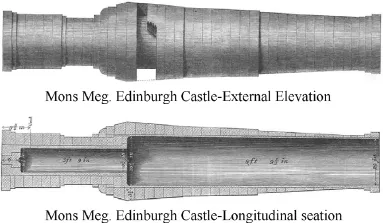
Fig.2.External and cross-sectional view of Mons Meg [6].

Table 1Pressured produced by period black powder compositions [7].
3.Internal ballistics
3.1.Muzzle velocity
To calculate the muzzle velocity of Mons Meg,the analytical code Proteus was used.Proteus is a 1 dimensional,lumped parameter code used to solve for combustion of gases and internal pressures;it is similar to IBHVG2 [8],and internal studies have shown the predictions of both codes to be comparable.
There were three likely black powder compositions in use during Mons Meg’s operation lifetime and one from when the barrel burst,each with a different range of pressure produced. Proteus matched these shot pressures to calculate the muzzle velocities.The results shown in Table 1 average the propellant mass and pressure range,whilst assuming a 160 kg granite cannon ball,to produce a single muzzle velocity for each composition.
As there is no def i nite source for which type of powder was used in Mons Meg,an average of the 14th and 16th century powders (its operational timespan)was used as the expected muzzle velocity of the cannon,315.0 m/s.This value was taken forward to be used in the external ballistics section.
The above value of 315.0 m/s was reached after several ref i nements to the model.An initial value of 319.1 m/s was previously calculated and used in both the external and terminal ballistics work as the research was running in close to parallel due to time and resource limits.
3.2.Internal pressure and the bursting of the barrel
As mentioned above in 1680,the barrel of Mons Meg burst during ceremonial duties.This section investigates whether the amount or type of powder could explain the manner and location of failure.
Following research from various sources,agreed values for the key dimensions of the cannon were used in the QinetiQ Barrel Design Software (QQ-BDAS).Although the method of manufacture of Mons Meg is different from that assumed in QQ-BDAS,it was decided that this software would give suff iciently representative pressure limits.
QQ-BDAS is a QinetiQ proprietary code and thus has not been referenced in open literature,although it was developed using the gun design calculation methods outlined in “Textbook of Ordnance and Gunnery”[9]authored by William H Tschappat,and “Vickers and Sons Maximum Ltd-Their works and manufacturers”[10]by Alex Richardson.
The cannon prof i le input in QQ-BDAS is show in Fig.3.
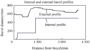
Fig.3.External and internal prof i les of Mons Meg used in QQ-BDAS.
An output from QQ-BDAS is a graph showing pressures along the barrel;this is shown in Fig.4.In this case the key information is the Safe Maximum Pressure which is shown in red,and the Margin of Safety shown in black.
QQ-BDAS does not use the internal pressure calculated in Proteus but uses the propellant impetus.This was set as a standard value for all the black powder compositions so they could not be individually compared.This does however show any “weak” points in the weapon using a black powder propellant.
The Safe Maximum Pressure is the theoretical maximum pressure that the cannon can contain,without sustaining damage,predicted by QQ-BDAS.The Maximum Internal Pressure Weald Hills (W/H)shows the theoretical propagation of gas pressure along the prof i le.The Margin of Safety is calculated as the ratio between the Safe Maximum Pressure and Maximum InternalWeald Hills Pressure.It is evaluated at every point along the cannon and varies from 1.3 to 9.6.A safety factor of 1.3 does not allow much room for error;this drop in safety occurs between 1.36 m and 1.74 m along Mons Meg,and extends roughly between hoops 3 and 7 from the breech end. This drop in factor of safety is caused by the internal diameter of the cannon increasing dramatically where the powder chamber opens out to accommodate the cannon ball.
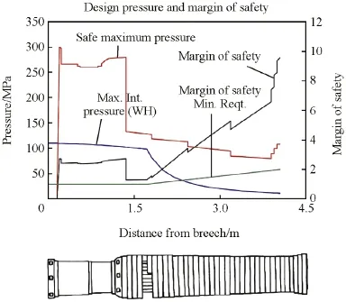
Fig.4.QQ-BDAS output compared Mons Meg failure location.
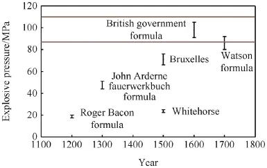
Fig.5.A comparison of black powder energetic potential [7].
The Margin of Safety Minimum Requirement is only relevant in modern weapons during strength of design investigations,but it gives a good reference point to show how safe Mons Meg was likely to have been to f i re.
By comparison between the graph and the location of failure along the cannon,shown in Fig.4,the damaged portion of Mons Meg,from the 1680 f i ring lines up very closely to the predicted drop in safe pressure from QQ-BDAS.This shows that the modern model of the cannon is a valid representation of the actual item and correctly predicts the area of failure.
Calculations from the Journal of the Ordnance Society [7]suggest that based on the mode of construction and the quality of iron used,the maximum permissible pressure within Mons Meg before damage starts to occur is 87 MPa.The same article states that a pressure of 110 MPa and over would be enough to destroy the barrel.
The pressure ranges of the black power compositions (as well as an earlier,weaker powder and a composition created after the bursting)compared to the two pressure limits above is show in Fig.5.This indicates the use of a more powerful powder,unavailable during Mons Meg’s operational lifetime,as the possible cause of the cannon’s failure in 1680.It cannot be ruled out that other factors may have assisted in the failure of the barrel;an inferior quality powder could have been used,which may have led to unstable def l agration,causing pressure waves to propagate along the barrel and in its worst form,this could lead to a minor detonation.Although it cannot be stated,with certainty,to be the cause of the barrel burst,we can show that the damage occurred at a weak point in the barrel’s construction.
4.External ballistics
4.1.Drag and pressure
The most important factor to consider when determining the trajectory of a fast moving projectile is drag.Drag refers toforces acting opposite to the relative motion of any object moving with respect to a surrounding f l uid and it is therefore used to calculate the deceleration of an object.Below is the drag equation

whereFD=drag force;ρ=mass density of the fl uid (air in the case of Mons Meg);u= fl ow velocity relative to the object;CD=drag coef fi cient;A=reference area.
As can be seen from Eq.(1),the drag force will increase as the velocity increases.The drag coef fi cient is a function of the Reynolds number and is therefore not constant meaning it will change for different velocities.There is no set formula to calculate it as it can only be approximated using experimental data and changes with numerous variables.The Reynolds number,Re,is a dimensionless quantity which is used to help predict similar fl ow patterns in different fl uid fl ow situations and incorporates several of these variables.

whereL=characteristic linear dimension (the diameter of the cannonball in this case);μ=dynamic viscosity of the fl uid.
Eq.(2)indicates thatReincreases with velocity.Air density and viscosity also affect the Reynolds number and how this is calculated will be discussed later.All ranges of Reynolds number have been included in the calculation of the drag coeffi cient but in reality only high velocity ranges will be needed as the projectile will still be travelling at over 100 m/s when it reaches its trajectory end point.
The Reynolds number relating to the drag on a sphere can be separated into fi ve separate categories [11]
1)Ideal or attached fl ow:Re<1,
2)Separated fl ow:1 <Re<10,
3)Unsteady oscillating fl ow:10 <Re<105,
4)Laminar boundary layer fl ow:105<Re<106,
5)Turbulent boundary layer fl ow:Re>106.
The most important stages when considering the Mons Megs cannonball trajectory are the fourth and f i fth stages as the projectile would remain within these f l ow stages for the duration of its f l ight due to the high velocity at which it would be travelling.
In the fourth case,a laminar boundary layer with a wide turbulent wake,the boundary layer on the windward side of the sphere is laminar and orderly and the chaotic wake is initiated as the f l ow turns onto the leeward side of the sphere [11].
The f i fth case is a turbulent boundary layer with a narrow turbulent wake.The boundary layer transitions to chaotic turbulent f l ow with vortices of many different scales being shed in a turbulent wake from the body.The separation point is initially slightly downstream from the laminar separation point,so the wake is initially slightly smaller and the drag is less than the corresponding laminar drag (stage 4)[11].In normal atmospheric conditions this equates to a velocity of around 250 m/s for the Mons Meg cannon ball.This velocity would be a lot higher if the projectile were smaller.The effect of Reynolds number on the drag coeff i cient is shown in Fig.6.
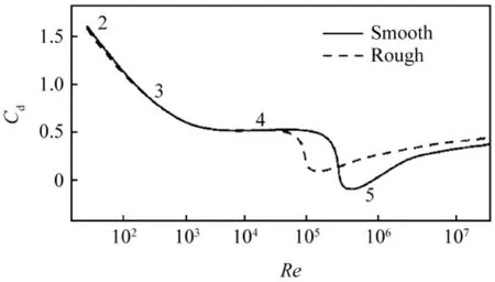
Fig.6.Relative change in drag coeff i cient with respect to Reynolds number[12].
4.2.Trajectory program
To calculate the trajectory of the cannonball,an analytical computer program was written in MATLAB.The program requires the user to de fi ne ground temperature,muzzle velocity,angle of the cannon with respect to the horizon and the mass of the projectile.The program calculates an initial air viscosity and density and resolves the velocity into x and y components.
The Mons Meg trajectory model calculates new air densities and viscosities as it steps through time.This is calculated from an initial ground temperature (i.e.wheny=0).At the beginning time step,a new temperature is calculated using the lapse rate,the rate at which the temperature decreases with increasing altitude and is equal to 6.4 °C/km under normal atmospheric conditions [13].Using this temperature the air density and viscosity can be calculated with the functionsρ(T)andη(T). These functions are polynomial interpolations of tables containing air density and viscosity as a function of temperatures[14].The main portion of the program is the loop which recalculates the velocity and maps the trajectory intoxandyarrays every 0.01 seconds,taking into account both drag and gravity. A time step of 0.01 seconds was used as a smaller time step does not affect the trajectory but does signi fi cantly increase the computation time of the program.This runs until the trajectory reaches ground level (y=0).
The drag model used in the program is taken from [15]and the trajectory model has been validated with data from [16].
4.3.Results
Initially the Mons Meg trajectory model was used to investigate the effect of changing the air temperature,initial angle and muzzle velocity has on the range of the bombard.Unless it is the variable being varied,the initial conditions of the program were a muzzle velocity of 300 m/s,initial angle of 15°,ground temperature of 15 °C and a projectile mass of 149 kg.This refers to a cannonball made from sandstone.
Table 2 shows that increasing the temperature from 0 °C to 30 °C increases the range of the cannon but only by 2.77%.This relationship is the lower air densities at higher temperatureswhich,when substituted into Eq. (1),will produce a slightly lower drag forces.Table 3 shows how range varies with initial cannon angle including percentage increase from 10°result.

Table 2Table showing how range varies with ground temperature including percentage increase from 0 °C result.

Table 3Table showing how range varies with initial cannon angle including percentage increase from 10°result.

Table 4Table showing how range varies with muzzle velocity including percentage increase from 210.8 m/s result.
Again,intuitively the range will increase as the initial angle is raised to 45°;however,this relationship is not linear.This is because the ranges are converging to a maximum which occurs at 45°.This was to be expected as can be seen in the experimental results found in [17].A 45°initial inclination would mean the muzzle of the cannon would be 2.86 m off the ground which is infeasible considering the mass of the cannon.It was agreed that a 15°inclination would be used for future trajectory calculations.
It is interesting to note that between 10°and 30°the terminal velocity decreases.This is because the projectile is spending longer in f l ight and is therefore affected by more drag.However,between 30°and 45°the terminal velocity increases again.This is because the projectile is reaching a higher altitude so the acceleration due to gravity is having a greater effect.Table 4 shows how range varies with muzzle velocity including percentage increase from 210.8 m/s result.
As to be expected,the higher muzzle velocities produced a signif i cantly greater range.The muzzle velocity range tested was suggested by the internal ballistics.
Two specif i c muzzle velocities were also tested,319.1 m/s and 315.0 m/s.These are the pre and post ref i nement predictions for the expected muzzle velocity of Mons Meg using period black powder.Table 5 shows the Mons Meg trajectory model results for the two calculated muzzle velocities.

Table 5Table showing the Mons Meg trajectory model results for the two calculated muzzle velocities.
Simulations have also been run using alternative methods,for example,using different atmosphere models and different drag models.However,the results showed that there were little differences in the predicted f i nal velocities and ranges,and the numbers stated in the paper represent typical values from the study.
5.Terminal ballistics
5.1.Background
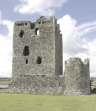
Fig.7.Modern day Threave Castle.Licensed under creative commons attribution-share alike 2.0 generic license [18].
One of the most famous stories about the bombard was the two month siege ofThreave Castle (Fig.7)by James II in 1455.The story goes that the f i rst cannonball f i red at the keep passed straight through the wall and severed the hand of Margaret Douglas as she was drinking inside.Although historians have discredited this account,this work investigated whetherthiswas possible.
This section also looks at the terminal ballistics of the cannon against modern targets,specif i cally a reinforced,monolithic concrete target.The impact conditions have come from the internal and external ballistics simulations discussed earlier.
Both analytical equations and hydrocode modelling were used to assess the capability of Mons Meg against period and modern targets.The cannonball was modelled as a 160 kg,490 mm diameter granite sphere and the target designs are described later.Several assumptions were made in this work,importantly the cannonball ball was assumed to behave as a rigid body.This was both a prerequisite of the analytical equations and necessary due to the lack of validated failure data for the material model used for the cannonball.
5.2.Analytical investigation
There is very little validation data for granite cannonball impacts.Anecdotal historical evidence exists for period,castletype targets but there is nothing in open literature for performance of a granite sphere impacting a modern concrete target. Therefore an analytical investigation was undertaken to provide data points from which to compare the hydrocode simulations for the modern target.
The analytical equations used are only valid for normal impacts so two different impact speeds were analysed,the muzzle velocity and fi nal velocity.These values provided the full range of possible depths of penetration for the cannon.
The analytical model used here was derived [19]from the Forrestal Spherical Cavity Expansion model.Forrestal et al. developed the empirical equations for predicting the penetration depth of projectiles into concrete and earth-type targets based on cavity expansion theory,taking into account the dimensions of the projectile (including nose shape),impact velocity and target properties [20].
Initially,an open-form analytical equation for penetration depth was used to estimate the depth of penetration [21].This split the penetration process into two regimes,a cratering phase(when the penetrator was less than two diameters into the targets)and a tunneling phase after that.The depth of penetration,P,equation for this is shown below
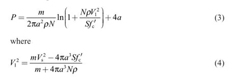
where the projectile has massm, radiusa,nose factorNbased on the calibre radius head,striking velocityVsand initial tunnel region velocityV1.The target is de fi ned by density,ρ,compressive strength,fc′ ,and a dimensionless empirical constant that multiplies the compressive strength,S.
However,the large calibre of the projectile,0.24 m for the cannonball,pushed the equations into non-realistic regimes withV1becoming imaginary.This is obviously unusable and therefore an earlier form of the spherical cavity expansion model was used [20].These equations were non-ideal and closed-form as several of the constants in the equations were derived from speci fi c target sets.Forrestal et.al.looked at the sensitivity to certain constants and found the difference to be negligible.However,the analytical equations for this study are mainly to provide added con fi dence to the hydrocode simulations and do not need to be precise.It was therefore decided that these equations would be suf fi cient to guide the hydrocode modelling and assumed that they hold valid for these scales of problem.
Here a spherical cavity is expanded at a constant velocity and produces a plastic response immediately surrounding the cavity and an incompressible elastic region around that.If the striking velocity is high enough,the plastic region can be represented by a locked hydrostat.As the velocity of the penetrator decreases,there is a transition velocity,Vt,where the linear hydrostat is a better approximation [19,20].This is governed by target material properties,speci fi cally the density and yield stressY.
The perpendicular force acting on a projectile is de fi ned in[20]
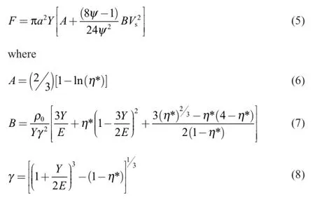
Here,Eis the Young’s Moduψlus,η*is the locked volumetric strain,taken as 0.04 [20],andis the calibre radius head of the projectile.In the case of a sphere or spherical noseψ=12;for a cannonball,this therefore reduces Eq. (5)to

Forces from both hydrostats can be written in the same form

Allowing the depth to be calculated from

Depth of penetration is then calculated for the locked hydrostat and then added to the linear hydrostat solution [20].

Table 6Depth of penetration values from analytical equations for maximum and minimum velocities.
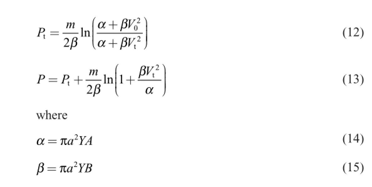
The internal and external ballistics calculations provided the maximum and minimum impact velocities.The standard modern target was set as a 50 MPa monolithic concrete target.
The values in Table 6 show a penetration depth of less than a radius of the cannonball for both impact velocities.The Muzzle Velocity impact is calculated from both hydrostats;however,the Final Velocity impact is already belowVtand therefore is drive solely by the linear hydrostat solution.
The analytical model predicts a modern target standing up very well to a large calibre cannonball.These values for penetration depth were used as sanity checks and comparisons to make sure the hydrocode simulations were producing sensible results.
5.3.Hydrocode simulations
Simulations were performed using the Lagrangian hydrocode DYNA3D which has a proven capability of predicting depth of penetration into different types of targets. DYNA3D includes advanced material models as well as advanced interface and fracture routines.
The granite cannonball was modelled using a simple elastic material model with aYoung’s Modulus of 50 GPa and a Poisson’s Ratio of 0.17 [22].This was modelled as a rigid body with no failure or fracture.This presented the “best-case” in terms of penetration where the cannonball itself does not deform or break up and would therefore have a deeper penetration depth than if it did fracture.
Two targets types were modelled,a 2 m thick,semi-inf i nite 50 MPa concrete target (replicating the analytical work)and a castle-type target.Depending on the impact conditions the scenarios were either simulated in quarter or half symmetry to reduce the computational load and run time.
The castle target was designed to be similar to Threave Castle,famously linked with Mons Meg.There is little available information about the exact properties of the stone and mortar that was used to construct Threave Castle but the stone was most likely taken from the surrounding land and held together with a lime mortar [23].
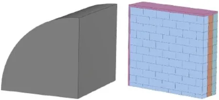
Fig.8.Quarter symmetry examples of modern and three layer castle targets.
The majority of the stone found in the moorland of Dumfries and Galloway,the location of the castle,is granite.As there was no validated failure and fracture model for granite available,a concrete model with a compressive strength of 200 MPa,granite’s minimum compressive strength [22],was used.The lime mortar was not explicitly modelled but simulated as interface between the individual bricks with a break stress of 1.5 MPa. Values for the strength of the lime mortar varied from 0.58 MPa to 2.37 MPa [24],therefore,1.5 MPa was used as the rounded median value.The castle target was simulated as a series of interlocking bricks in several layers with a steel surround to help conf i ne the bricks.Fig.8 shows the hydrocode set-up for the two target types.
5.3.1.Modern targets
Guided by the analytical equations and the results above,the 50 MPa concrete target was 2 m thick to provide a semi-inf i nite target to properly predict depth of penetration.It was also over 20 times the cannonball radius in diameter in order to remove edge effects.Three impact scenarios were simulated to investigate the range of possible penetration depths and any effect of ricochet.
Similar to the analytical modelling,the hydrocode predicted penetration depths less than the radius of the cannonball.
Fig.9 below shows the f i nal state of the hydrocode modelling for the normal impacts.Table 8 and Fig.10 show the data and compares it to the analytical results.
The larger difference seen for the f i nal velocity impact simulation is most likely due to the analytical model relying on the linear hydrostat equations which may not be valid at the scales involved.
The f i nal velocity from the external ballistics exercise was also simulated with the angular impact(Table 7).This required the simulation to be performed in half symmetry due to the asymmetrical impact conditions.The f i nal state of the hydrocode simulation for this angled impacts in shown in Fig.11.
The hydrocode simulations are in close agreement with the analytical modelling,within 6%for the higher velocity impacts,giving added conf i dence to the hydrocode results.There is very little difference between the normal and angled impacts for the 209.2 m/s impact velocity.There is not enough engagement for the angle of attack of the cannonball to have any pronounced effect.

Fig.9.Maximum depth of penetration for normal impacts at (a)319.1 m/s and (b)209.2 m/s.
The data above shows that modern defensive structures would hold up very well against a 13th century siege weapon. Even at point blank range the cannonball will,at most,leave a small dent in the concrete and most likely ricochet or bounce off the target.

Table 7Impact conditions for modern target hydrocode simulations.

Table 8Maximum depth of penetration for hydrocode and analytical modelling and the difference between them.

Fig.10.Graph of maximum depth of penetration in the hydrocode model compared to the analytical model.The angled impact condition only has the hydrocode result due to the analytic model being limited to normal impacts only.
5.3.2.Period castle targets
Castle construction often used stones and rock that were locally sourced and simply picked up from the ground which meant that there is a wide range of stone sizes in most castle walls.It is,however,diff i cult,complicated and time consuming to replicate this construction in the simulations so the targets were designed with separate layers of interlocking bricks,with breakable “slideline”interfaces (described previously)between both the bricks and the separate layers.
Threave Castle keep is described as being 3 m thick but the number of bricks,cells and interfaces required to model this size target is beyond the capability of DYNA3D to run in any sensible timeframe.Therefore this investigation looked at the penetration and perforation trend when the number of layers and the thickness of the bricks in a 3 layered target are increased.This data was then extrapolated into the penetration performance of Mons Meg.
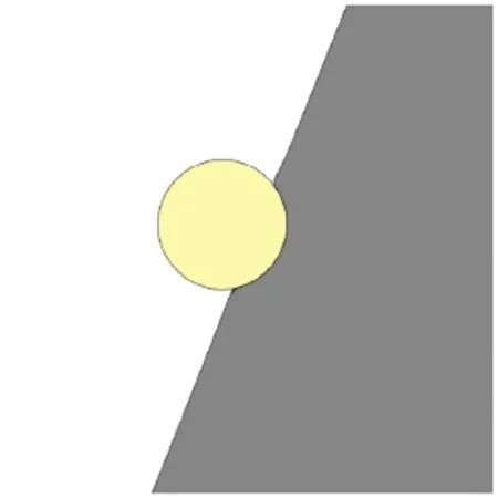
Fig.11.Maximum depth of penetration for 21.3°,209.2/s impact.

Table 9Table summarizing the exit velocities and depths of penetration (DoP)against varying period targets.The estimates of the exit velocity were necessary as the cannonball had not completely cleared the target.
Thebricksused in thisinvestigation wereinitially 260 mm × 260 mm × 520 mm.The target width and height was over 10 times the diameter of the cannonball to remove edge effects in the simulation.For targets with multiple layers,the brick layout in the rows was staggered alternatively between layers so there was not a single interface failure path through the thickness of the target.The number of cells in the simulations,proportional to the computational load,was the limiting factor for the number of layers,restricting it to three.Each layer of bricks added roughly 635,000 cells,pushing the three layer target close to 2 million cells in quarter symmetry.
Due to the concern of the number of computational cells mentioned above,the simulations were limited to the “best penetration”case,a muzzle velocity of 319.1 m/s normal impact,allowing the modelling to be performed in quarter symmetry.
Table 9 shows the results for the period castle targets modelled.The size of the bricks used and the number of layers is compared to the exit velocity and,if the cannonball was arrested by the target,their f i nal depth of penetration.
Fig.12 shows the impact against a single layer brick target. There are two different failure mechanism occurring:(i)the brick along the central axis is simply pushed out of the way once the 1.5 MPa failure stress of the slideline is reached and is then free to move and (ii)the cannonball “tears”through the other bricks as it passes through the wall.Mons Meg could easily perforate a 260 mm thick single layer brick wall and has an exit velocity of 162 m/s.
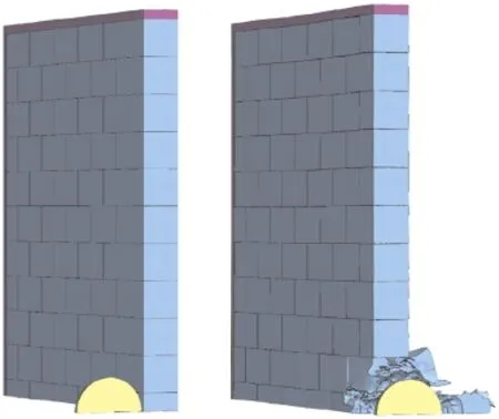
Fig.12.Pre and post impact images of single layer brick target impacted normal at the muzzle velocity of Mons Meg.

Fig.13.Pre and post impact images of double layer brick target impacted normal at the muzzle velocity of Mons Meg showing brick interface issues.
The two layer target unfortunately encountered some numerical instability along the brick to brick interfaces which cause the simulation to crash before completion.It did however run long enough for some initial conclusions to be made. Fig.13 shows the bricks in the second layer in the path of the cannonball,and central axis brick of the f i rst layer,have already been pushed out and are travelling with a velocity greater than the cannonball at the last time,implying they will have no further effect on the result.
The velocity prof i le of the cannonball has also plateaued at roughly 60 m/s.All the bricks along the shot line,having failed break interfaces,are moving out of the way.This is thus assumed to be the predicted exit velocity of the cannonball with the caveat of qualitatively larger error bounds for this result.
The impact against the three layer target was very similar in response to that seen in the two layer target.The velocity prof i le of the cannonball plateaued at roughly 24 m/s.Fig.14 shows the initial and f i nal state of the hydrocode modelling.
If these three results are extrapolated,assuming a linear decreasing trend of exit velocity as the number of layers of bricks are increased,to stop the cannonball the wall requires at least four layers of 260 mm thick bricks.

Fig.14.Pre and post impact images of triple layer brick target impacted normal at the muzzle velocity of Mons Meg showing brick interface issues.
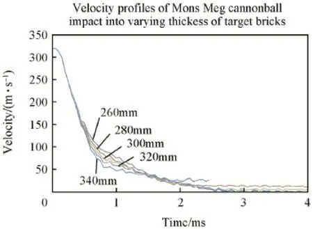
Fig.15.Graph showing cannonball velocity prof i le through three layered targets of differing thickness of brick.
The thickness and size of the individual bricks in the three layer target were also increased in increments of 20 mm thickness,as shown in Table 9.Fig.15 presents the velocity prof i les of the simulations and the results show that the 320 mm and 340 mm thick bricks stop the cannonball in the target.
6.Conclusions and recommendations
Internal ballistics codes and calculations provided an average expected muzzle velocity of 315.0 m/s for black powder available during Mons Meg’s operational lifetime.The following external ballistics works investigates trajectory of the cannonball using this muzzle velocity.A value of 319.1 m/s was also examined in the external and terminal ballistics sections due time constraints.
QQ-BDAS also correctly predicts the weak point in the cannon where it failed and postulates that the use of a more modern,powerful black powder could have been the cause of the barrel bursting.
The Mons Meg trajectory model was used to investigate the effect of varying air temperature,initial angle and muzzle velocity.
The f i nal speed and trajectory of the internal ballistics’expected muzzle velocities was also calculated and carried forward to investigate the cannon’s terminalballistic performance.
This section began talking about the siege of Threave Castle and whether Mons Meg could break through the keep walls with enough residual velocity to remove the hand of a person inside.The hydrocode modelling has shown that,even with ideal conditions in terms of impact velocities,target design and rigid projectile material,the cannonball would fail to break through a 1.0 m period castle wall,let alone the 3 m thick keep walls of Threave Castle.This agrees with the lack of cannon damage to the keep,which is still standing to this day.Mons Meg is also predicted to have very little effect on modern concrete targets.
These attempts to simulate period weaponry and castle targets have provided many lessons learnt.To accurately model the scenarios in the hydrocode,material tests will be needed to def i ne the material models and failure criteria.This would mean failure in the cannonball could be implemented which may dramatically affect the results.The design of the target can be made more representative of the “real life”structure by explicitly including the mortar between the stones and rocks.The size and distribution of the stones can also be improved including have larger rocks spanning several layers.It would also be interesting to model the castle-type target for an angled impact. This would remove the mechanism of the bricks along the axis simply being pushed out the back.
[1]Wikipedia.Mons Meg-wikipedia [Online]. <https://en.wikipedia.org/ wiki/Mons_Meg>;2015 [accessed 15.09.2015].
[2]Gaier C.The origin of Mons Meg.J Arms Armour Soc 1967;5(12):425-31.
[3]Smith RD,Brown RR.Bombards:Mons Meg and her sisters.London:Trustees of The Royal Armouries;1989.
[4]Kinard J.Artillery:an illustrated history of its impact.ABC-CLIO;2007.
[5]Birchon D.Dictionary of metallurgy.London:Newnes;1965.
[6]Mallet R.On the physical conditions involved in the construction of artillery.1856.
[7]Gillet C,Lefebvre M,Galloy J.A technological success in the 15th century:Jehan Gambier’s Mons Meg.J Ordinance Soc 2004;16:16-25.
[8]Anderson RFK.IBVHG2.U.S.Army Ballistic Research Laboratory;1987.
[9]Tschappat WH.Text-book of ordnance and gunnery.John Wiley;1917.
[10]Richardson A.Vickers and Sons Maxim Ltd-their works and manufacturers.Strand:Off i ces of “Engineering”;1902.
[11]Falkovich G.Fluid mechanics.Cambridge University Press;2011.
[12]NASA.Drag of a sphere [Online]. <http://www.grc.nasa.gov/WWW/ k-12/airplane/dragsphere.html> [accessed 15.09.15].
[13]Jacobson MZ.Fundamentals of atmospheric modelling.2nd ed. Cambridge University Press;2005.
[14]Dry air properties [Online].<http://www.engineeringtoolbox.com/dry-air -properties-d_973.html> [accessed 15.09.15].
[15]Subramanian RS.Drag on spherical particles and steady settling velocities[Online]. <http://web2.clarkson.edu/projects/subramanian/ch301/notes/ dragsphere.pdf> [accessed 08.12.15].
[16]McCoy RL.Modern exterior ballistics.Atglen,PA:Schiffer Publishing Ltd.;2012.
[17]Sedat Biringen C-YC.An introduction to computational f l uid mechanics by example.John Wiley&Sons;2011.
[18]Wikipedia.Threave Castle-wikipedia [Online]. <https://en.wikipedia .org/wiki/Threave_Castle> [accessed 15.09.15].
[19]Forrestal MJ,Luk VK.Dynamic spherical cavity-expansion in a compressible elastic-plastic solid.J Appl Mech 1988;55(2):275-9.
[20]Forrestal MJ,Luk VK.Penetration into semi-inf i nite reinforced concrete targets with spherical and ogival nose projectiles.Int J Impact Eng 1987;6:291-301.
[21]Forrestal MJ,Altman BS,Cargile JD,Hanchak SJ.An empirical equation for penetration depth of ogive-nose projectile into concrete targets.Int J Impact Eng 1994;15(4):395-405.
[22]Stone RL.Strength and deformation properties of granite,basalt,limestone and tuff at various loading rates.Vicksburg,Mississippi:U.S. Army Engineer Waterways Experiment Station;1969.
[23]Mackenzie W,Symson A.This history of Galloway:from the earliest period to the present time.Kirkcudbright:John Nickolson;1841.
[24]Pavia S,Fitzgerald B,Treacy E.An assessment of lime mortars for masonry repairs.In:Concrete research in Ireland colloquium.Dubline:2005.
Received 28 September 2015;revised 30 November 2015;accepted 1 December 2015 Available online 23 December 2015
Peer review under responsibility of China Ordnance Society.
*Corresponding author.Tel.:+44 1959514029.
E-mail address:ramcalister@qinetiq.com (R.MCALISTER).
http://dx.doi.org/10.1016/j.dt.2015.12.001
2214-9147/© 2016 China Ordnance Society.Production and hosting by Elsevier B.V.All rights reserved.
© 2016 China Ordnance Society.Production and hosting by Elsevier B.V.All rights reserved.
- Defence Technology的其它文章
- Mechanism of plasma ignition in electrothermal-chemical launcher
- 3D numerical simulation and analysis of railgun gouging mechanism
- Calculation of propellant gas pressure by simple extended corresponding state principle
- Application of transient burning rate model of solid propellant in electrothermal-chemical launch simulation
- Innovative boron nitride-doped propellants

