Design and Experiment of Fluid Dynamic Ultrasonic Water Aerator
, , , , ng
College of Engineering, Hunan Agricultural University, Changsha 410128, China
1 Introduction
Aeration is an essential part of aquaculture, sewage treatment and aerated irrigation fields, and aeration effect directly influences growth condition of aquatic animals, quality of sewage treatment, growth and quality of crops. Traditional aeration methods include enhanced aeration (i.e. aerator) and electrical aeration, while new aeration methods include magnetized aeration, photochemical aeration, biochemical, materialized, and emulsified (ultrasonic) aeration[1]. The efficiency of enhanced aeration is low and it generates large bubble; electrical aeration consumes high energy; motored ultrasonic aerator can not operate continuously, consumes high energy, and the efficiency is low, accordingly the application of motored ultrasonic aerator is limited[2]. Fluid dynamic ultrasonic aerator is a new water aeration technology, its structure is simple, sturdy and durable, and its handling capacity is high, energy consumption is low and equipment cost is low[3-4], and the aeration efficiency is high and operation is simple. The saturated solubility of oxygen in water is very low. To bring oxygen in water to reach saturation state, oxygen has to exist in water in numerous tiny bubbles to reach high efficient aeration. Using ultrasonic wave, fluid dynamic ultrasonic aerator further breaks bubbles in water, brings dissolved oxygen in water to reach saturation or even supersaturation state, thus this new technology has broad application prospect in aquaculture and sewage treatment[5-6]. In this context, we studied and designed a fluid dynamic ultrasonic water aerator, to solve the problem of low dissolved oxygen in industrial sewage, pond water, and irrigation water.
2 Operating principle
The operating principle for this fluid dynamic ultrasonic water aerator is as follows. High speed water flows through Venturi pipe and generates negative pressure to suck air, brings air into water to form tiny bubbles. As illustrated in Fig. 1, high speed water flow with air attacks reed through the nozzle, brings reed to vibrate and generate ultrasonic, which will further break tiny bubbles and form ultra tiny bubbles. Besides, because water flow is very fast in fluid dynamic ultrasonic water aerator, it may bring about hydraulic cavitation problem[7-8], in other words, formation of cavities in fluids; when liquid flows rapidly, bubbles will constantly generate and break[9], in this way, it increases conditions for formation and break of bubbles in water. Since the movement in aerator belongs to gas-liquid two-phase flow, the movement is relatively complex[10].
3 Structural design of the fluid dynamic ultrasonic water aerator
From Fig. 1, it can be seen that the fluid dynamic ultrasonic water aerator includes three parts: I section (inlet pipe and transition section), II section (inlet port and nozzle), and III section (reed holder, reed, and outlet pipe).
3.1StructuraldesignofIsectionI section consists of inlet pipe and transition section which are flanged connected. The design of I section mainly lies in the transition section. I section belongs to inlet section of the fluid dynamic ultrasonic water aerator, and its shape selection should be based on analysis of cavitation flow field. Studies have shown that there are 3 types available: cylindrical, conical, and curved. From comparison, conical shape inlet section generates most violent cavitation effect. Cylindrical transition leads to thickening of throat boundary layer, narrows actual flow path of throat. High speed water flow fails to expand completely within pipe, and local losses will increase, speed attenuation at nozzle outlet increases, and local absolute pressure increases, not favorable for formation of tiny bubbles[11]. Jet of curved nozzle gradually becomes complete expansion in throat. Both the transverse pressure gradient and radial velocity component generated from the inlet section gradually decline, and tend to become zero before the nozzle outlet, to obtain uniform outlet flow field, leading to no violent turbulent flow in the flow field, so as to reduce the cavitation intensity[12].
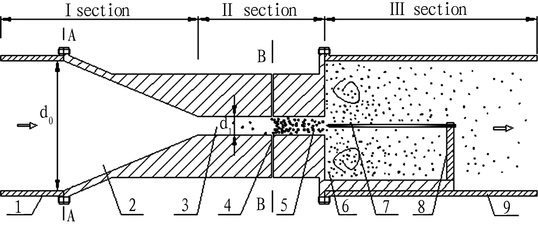
1: inlet pipe; 2: transition section; 3: throat; 4: inlet port; 5: nozzle; 6: sudden-expansion part; 7: reed; 8: reed holder; 9: outlet pipe
Fig.1Corecomponentsofthefluiddynamicultrasonicwateraerator
For conical transition section, the inlet diameterd0=50 mm, and outlet diameterd1can be calculated by equation (1)[13].
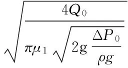
(1)
whereQ0denotes the flow;μ1signifies the flow coefficient (0.95-0.98 for conical and streamlined nozzles); ΔP0is operating pressure;ρis water density;gis gravity acceleration. Through calculation,d1=6.5 mm.
In this study, the nozzle is designed to be rectangular nozzle, so the outlet diameterd1=6.5 mm converted to rectangular size 20 mm × 7 mm. In Fig. 1, A-A section and B-B section are inlet and necked-down section respectively. The neck-down section converts pressure into flow velocity, while the sudden-expansion section converts flow velocity into pressure. Due to shrinkage of neck-down section area, the flow velocity increases, while the air pressure drops. Bernoulli differential equation for A-A section and B-B section is shown in equation (2).

(2)
where subscriptsAandBrefer to A-A section and B-B section in Fig. 1;pis pressure;zis elevation;vis velocity;hwis head loss when water flows through A-A section and B-B section, because the spacing between two sections is small, it can be ignored;ρis water density;gis gravity acceleration.
According to equation (2), the principle for this device: because throat diameter shrinks suddenly, average velocity of water in flow pathvBincreases, pressurepBsuddenly declines, when it becomes lower than atmospheric pressure, air will flow in through the inlet port, and it will be cut off by high velocity water and mixed together to form tiny air bubbles.
3.2StructuraldesignofIIsectionII section is throat section which consists of rectangular nozzle and inlet port. The rectangular nozzle is to render high velocity water to apply uniform force on the reed. Two inlet ports in upper and lower respectively are used, to ensure uniform air suction of rectangular nozzle[14]. Throat is a key component in this fluid dynamic ultrasonic water aerator. The throat length and size play a great role in transfer of oxygen dissolving molecules in water. Some experts proposed the length-diameter ratio for air-liquid jet pump is 6-8[15]. In this experiment, we mainly considered air suction capacity of water aerator, little consideration is taken into air-liquid mixing at the throat. Thus, according to rational overall structure, we took 8 as the length-diameter ratio of throat.
3.3StructuraldesignofIIIsectionIII section is ultrasonic section, consisting of reed, reed holder and outlet pipe. The reed is horizontally positioned and aligned with center of rectangular nozzle. The connection between III section outlet pipe and II section is sudden expansion, so that after breaking by reed ultrasonic, the high velocity water flow with bubbles sprayed by rectangular nozzle forms complex turbulent flow in outlet pipe, to realize full contact of air with liquid[16]. Reed whistle is arranged at the end of Venturi throat nozzle. High velocity water sprayed by nozzle strikes reed whistle to generate high frequency vibration and form ultrasonic wave. The aeration effect is closely connected with whether inherent frequency of reed and inherent frequency of liquid-flow reed reaches the harmonic frequency. According to reference[17], the base inherent frequency of cantilever reed whistle can be calculated using equations (3)-(5).
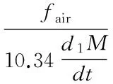
(3)

(4)
M=1.8lk
(5)
wheretis reed thickness,kis reed width,lis reed length (effective vibration part),dis reed density,dlis liquid density,Mis reed mass, andEis Young’s modulus of reed material. The fluid dynamic ultrasonic frequency is 20-30 kHz. According to calculation, reed thicknesst=0.8 mm, widthk=20 mm, and lengthl=40 mm.
The American Society of Civil Engineers (ASCE) introduced the mass transport model of dissolved oxygen (DO). As shown in equation (6), considering mass transfer of bubble-water interface, we used mass transfer coefficient of oxygen volume to measure the water aeration efficiency.
(6)


(7)
whereC0is initial mass concentration of DO. The oxygen volume mass transfer coefficient changes with temperature. To unify temperature for comparison, with reference to theory introduced by the American Society of Civil Engineers[18], the oxygen volume mass transfer coefficient can be converted into the relational expression at standard temperature 20℃ from experiment temperature, as shown in equation (8).
(KLa)20=(KLa)θ×1.024(20-θ)
(8)
where (KLa)20is oxygen volume mass transfer coefficient at 20℃[19].
4 Experiment device and preliminary experimental results
4.1ExperimentdeviceAccording to the above description of structural design of the fluid dynamic ultrasonic aerator, we designed the complete set of experiment device[20,21], and carried out dissolved oxygen experiment in hydraulics laboratory in Hunan Agricultural University, as illustrated in Fig. 2.
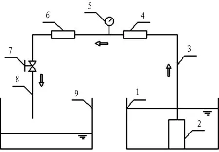
1: inlet tank; 2: water pump; 3: inlet pipe; 4: vortex flow meter; 5: pressure gauge; 6: core component of aerator; 7: valve; 8: outlet pipe; 9: outlet tank
Fig.2Schematicdrawingforfluiddynamicultrasonicwateraerator
4.2PreliminaryexperimentandresultsMajor components of experimental device include core component, water pump, Φ50 vortex flow meter, Φ50 inlet pipe and outlet pipe, and valve. Experiment conditions: the concentration of dissolved oxygen is 4.78-4.80 mg/L, and water temperature is 28.0℃. Measurement instrument: SG9 dissolved oxygen determining instrument, liquid vortex flow meter, and precision pressure gauge. We carried out the experiment in hydraulics laboratory of Hunan Agricultural University in August 2015. Water pump draws water from the inlet tank, water flows to inlet pipe, the flow meter, then the aerator, finally flows out from outlet pipe. Before entering the aerator, set the pressure meter to measure the inlet pressure; at the outlet pipe, arrange a valve to control the flow rate of the entire device. Start the water pump, slowly open the valve, to bring the flow rate of entire device to reach the stable valueQ=9.7 m3/h, the inlet pressure reading is 0.146 MPa. At this time, collect 3 barrels of experimental water to measure the dissolved oxygen. We compared the dissolved oxygen of water with and without reed, and compared the standard saturated dissolved oxygen and initial dissolved oxygen at current temperature. The experiment results are shown in Fig. 3.
According to Fig. 3, when reed is added, the ratio of measured dissolved oxygen to saturation value is 1.015; when there is no reed, the ratio of measured dissolved oxygen to saturation value is 0.776. When there is reed, the dissolved oxygen exceeds standard saturated dissolved oxygen at current temperature and reaches the supersaturation state; when there is no reed, the dissolved oxygen has slight increase compared with the value before aeration, but there is still a gap of 1.75 mg/L with the saturation value. From the above analysis, it can be known that the designed fluid dynamic ultrasonic water aerator has significant aeration effect, and it can bring the experimental water to saturation state or even supersaturation state.
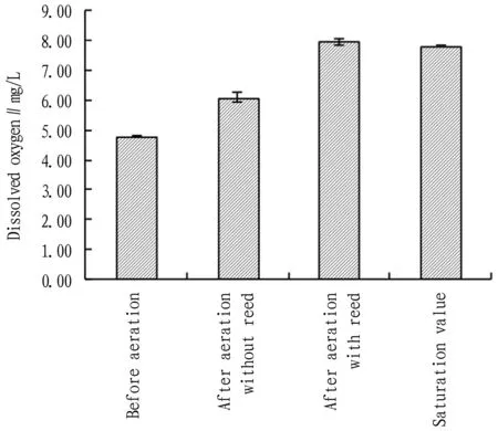
Fig.3Comparisonofdissolvedoxygenintwotypesofexperimentalwater
5 Conclusions and discussions
The experiment results indicate that this fluid dynamic ultrasonic water aerator has higher aeration efficiency than other conventional aerators. Besides, it can rapidly increase dissolved oxygen in water. In existing aerators and systems, few can reach such level. For the new study direction, aerated irrigation, the aeration is mainly realized through a long time air pump injecting air, which is difficult to bring the dissolved oxygen in water to reach the saturation state. However, the fluid dynamic ultrasonic water aerator can solve this problem. At present, this device still remains at the study and experimental stage. We will study how to produce water with high dissolved oxygen, so as to apply this device in actual production as soon as possible.
In this study, we designed structure of the fluid dynamic ultrasonic water aerator, produced the complete set of fluid dynamic ultrasonic water aerator, and also analyzed the dissolved oxygen in experimental water. The experiment results of this device show that when high speed water flows core component of the aerator, it can rapidly bring dissolved oxygen in water to reach the saturation state or even supersaturation state, the aeration effect is highly significant. This study explored a new design method and new aeration technique for design and application of water aerator, and will provide important reference and application value for sewage treatment, aquaculture, and aerated irrigation of plants. However, this device still remains at the study and experimental stage. Thus, we will study how to produce water with high dissolved oxygen, so as to apply this device in actual production as soon as possible.
[1] DING YL. The current situation and development of the application of oxygen-addition technique [J].Fishery Modernization,1978(3):15-19. (in Chinese).
[2] LIU S, ZHU BZ, WANG W. Performance of rotating packed beds in increasing dissolved oxygen in water [J]. Chemical Industry and Engineering Progress, 2010(S2): 38-40. (in Chinese).
[3] LU B, GUAN JT, ZHANG JG,etal. Research situation of hydrodynamic high intensity sound source [J]. China Petroleum Machinery, 2002, 30(4): 45-48. (in Chinese).
[4] CHAKINALA AG, GOGATE PR, BURGESS AE,etal. Treatment of industrial wastewater effluents using hydrodynamic cavitation and the advanced Fenton process [J]. Ultrasonics Sonochemistry, 2008,15(1):49-54.
[5] CAI YZ. The design and study of ultrasonic micro bubbles generator and technique [D]. Hangzhou: Hangzhou Dianzi University,2013:9-15. (in Chinese).
[6] SUN XY. Recent research advances of ultrasonic atomizer [J].Industrial Furnace,2004,26(1):19-23,32. (in Chinese).
[7] ZHANG LF, XIA WH. Cavitation and cavitation erosion [M]. Nanjing: Hohai University Press, 1989:24-27. (in Chinese).
[8] GAO QS. Further exploration of liquid cavitation mechanism [J].Journal of Hohai University (Natural Sciences),1999,27(5):63-67. (in Chinese).
[9] ZHANG CC, LV XP, HAN PF. Application of liquid whistle ultrasonic generator for circulation water sterilization [J]. Chemical Reaction Engineering and Technology,2012,28(1):70-74,86. (in Chinese).
[10] LI ZK, ZHANG ZH, GUO S,etal.Research on jet bubble generator for microbubble floatation [J]. Mining Research and Development, 2007, 27(5):54-56. (in Chinese).
[11] HE F, XIE JS, YANG JL. Effect of nozzle geometry on aerodynamics of free jet [J].Chinese Journal of Applied Mechanics,2001,15(4):114-120. (in Chinese).
[12] YUAN Y, WU SJ, SU J,etal. Effect of nozzle shape of reed-whistle on cavitation flow field [J].Technical Acoustics,2009,28(6):64-67. (in Chinese).
[13] LU HQ. The theory and application of jet pump technique [M]. Beijing: China Water Power Press,1989. (in Chinese).
[14] PANG YZ, LI XJ. Design of water-air spurting aerator used under ice and in deep water and experimental study on its performance [J]. Transactions of the Chinese Society of Agricultural Engineering,2003,19(3):112-115. (in Chinese).
[15] JIANG LY, LU YY, WANG J,etal. Experimental study on optimal nozzle-to-throat clearance of jet aerator [J]. Fluid Machinery,2010,38(11):1-5. (in Chinese).
[16] LIU H, WANG JH. An experimental study of ultrasonic atomizer [J]. Journal of Jiangsu Polytechnic University,2005,17(1):31-33. (in Chinese).
[17] LUO ZY, DENG WH. Study onthe working characteristics of A6 cantilever reed [J]. Technical Acoustics,1996,15(4):166-169. (in Chinese).
[18] ASCE, ANSI/ASCE2-91. Standard measurement of oxygen transfer in clean water [S]. New York: American Society of Civil Engineers,1992:11.
[19] CHENG XJ, KUANG YQ, LIN WX,etal. Effects of arrangement of venturi aerators on aeration in re-circulating water [J].Journal of South China University of Technology(Natural Science Edition),2015,43(3):121-129. (in Chinese).
[20] LI X, PEI Y, YAO BS,etal. A generator and system of ultrasonic microbubble based on hydraulic combination[P].China Patent, ZL201520358920.0,2015-10-21. (in Chinese).
[21] PEI Y, LI X, YTAO BS,etal. A generator and system of ultrasonic microbubble based on hydraulic combination[P].China Patent, ZL201510284880.4,2016-02-24. (in Chinese).
 Asian Agricultural Research2016年9期
- Asian Agricultural Research的其它文章
- Empirical Study on the Relationship between Organizational Flexibility and Performance of Agricultural Enterprise
- Correlation between Employment Quality and Skill Training of Land-expropriated Farmers
- A Study on Spatial Distribution of Commercial Housing Prices in Xiangtan City
- The Relation between Age Structure of Population and Resident Consumption Based on Endogenous Growth Theory
- Effect of Different Pretreatments on Explosion Puffing Drying of Hami Melon at Modified Temperature and Pressure in Xinjiang
- Design and Implementation of National Meteorological Service Platform
