Comparative study between the single frequency and synchronous double frequency induction hardening technique for gear
Xing-ye JIN,Guang-hao SONG,Wei-gang ZHENG(School of Energyand Power Engineering,Wuhan University of Technology,Wuhan 430063,China)(Engineering Training Center,Wuhan University of Technology,Wuhan 430063,China)
Comparative study between the single frequency and synchronous double frequency induction hardening technique for gear
Xing-ye JIN1,Guang-hao SONG1,Wei-gang ZHENG2*
(1School of Energyand Power Engineering,Wuhan University of Technology,Wuhan 430063,China)
(2Engineering Training Center,Wuhan University of Technology,Wuhan 430063,China)
According to different module and shape of various types of gears,the depth,hardness and microstructure of hardened layer,and the application range required by heat treatment distortion,this paper conducted a comparison study for the application of several gear hardening techniques,i.e.,high frequency,intermediate frequency,double frequency and SDF synchronous double frequency induction hardening techniques.
Gear heat treatment distortion,High frequency induction hardening,Intermediate frequency induction hardening,Synchronous double frequency induction hardening
Hydromechatronics Engineering
http://jdy.qks.cqut.edu.cn
E-mail:jdygcyw@126.com
1 Induction hardening distortion of gears
1.1 Characteristics
In the induction heating process,as a result of the current skin effect,the surface of the gear,as the only heated part,has the highest temperature and the core of the gear has the lowest temperature.The tissue distribution on the fracture surface of the hardened gear mainly depends on the temperature distribution.
The heat on the gear surface enables a great regional stress to be formed in the workpiece,which will lead to the non-uniform plastic distortion of the workpiece.This regional residual stress is much greater than the residual stress generated by conventional heat treatment.
1.2 Process
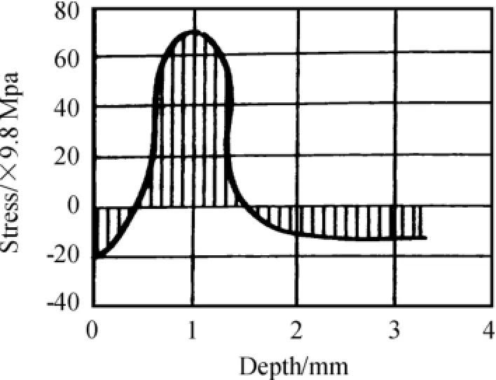
For gears that should be fully induction hardened, their inner holes often become the key part of distortion since there are a great number of keyways within them.In the process of induction hardening,as a result of the change of temperature and microstructure,the gear will produce thermal stress and structural stress.The residual stress distribution within the gear after induction hardening is shown in Figure 1.As the inner holes are compressed by the stress,they will become narrow after the induction hardening process. The level of compressive stress is mainly determined by the level of the thermal stress.
1.3 Factors
Main factors contributing to the high-frequency induction hardening distortion are gear shape,heat treatment technique,cooling method,the sensor’s structure and the residual stress of mechanical operation etc.The performance of gear distortion varies according to the shape of the gear.
2 The high frequency induction hardening technique of gear
The residual stress distribution within the gear after high-frequency induction hardening is shown in Figure.1.There is a great amount of compressive stress focusing on the surface of the gear,which will produce a positive effect on the fatigue property of the workpiece.But there exists a great tensile stress inside the workpiece,which will lead to a negative effect on the mechanical properties of the workpiece,especially gear crack,or even cracking.Therefore,it is necessary to attach importance for the induction hardening process.

Fig.1 The residuaI stress distribution within the gear after high-frequency induction hardening
The high-frequency induction hardening distortion of gear includes single-tooth distortion and overall distortion.The characteristics of the single-tooth distortion are associated with heating temperature.When the gear is cooled at a temperature under the phase transition point,the tooth top will be contracted and the pitch circle will be swelled.When the gear is hardened at a heating temperature above the phase transition point,the tooth top will be basically contracted and the tooth thickness gets increased.
For high frequency induction hardening,gears with modulus less than 3.5 mm have similar characteristics with cylindrical or disk-shaped gears.The gear inner diameter will be contracted as a result of the thermal effect.The martensitic structure will be formed on the surface layer merely partly compensates the inner diameter reduction of the gear caused by the thermal effect.Hardening the tooth groove may result in the distortion of the whole gear contour.
Parameters of the high frequency heating process(such as time,temperature,etc.)greatly influence the gear distortion.The longer the gear is heated,the more intense the thermal effect is and the more the inner hole’s diameter reduction is.For example,for a gear of intermediate modulus whose inner hole’s diameter is 25mm,the contraction is about 0.012 7 mm.Improving the heating temperature or increasing the depth of the hardened layer can reduce the contraction of the inner hole’s diameter.According to the gear size,when the temperature reaches a higher point,the inner hole’s diameter begins to increase. The minimum degree of gear distortion can be obtained by adjusting the heating process.
For gears born with keyway in their inner holes,the high frequency induction hardening can easily lead to the distortion of gear pitch circle.The inside diameter reduces in the direction of keyway and increases in the opposite direction.When the gear shaft or inner hole bears with two symmetrical gear keyway,the distortion produced by hardening reaches the highest level.Increment in the symmetrical keyway will lead to the decrease of distortion.
Generally,the gear distortion caused by high frequency induction hardening should meet the following requirements.
1)When the modulus(m)is no more than 5 m and the tooth width is less than 40 mm,after high frequency induction hardening,the teeth distortion less than 0.01 mm is allowed.When modulus(m)is or less than 5 m and the tooth width is less than 40 mm,after high frequency induction hardening,the teeth distortion less than 0.015 mm is allowed.
2)In accordance with the thickness of wall,the gear spline distortion limit can be divided as follows:when gear’s minimum diameter or maximum hole diameter is no more than 2 mm,the reduction should be no more than 0.05 mm;when gear’s minimum diameter or maximum hole diameter is greater than 2 mm,the reduction should be no more than 0.03 mm.
3)The Intermediate Frequency Induction Hardening Technique of Gear
When the gear rack receives one-side heating hardening,asymmetric hardened layer also exists,which can cause bending or warping.If the rack is large and the hardening layer is shallow,distortion will be smaller;if the rack is thin,in the process of one-side hardening its variables will be large and difficult to correct.
For custom-making gear intermediate frequency induction hardening technique,we should fully consider the effective control of the hardening layer depth,making it reasonably distribute so as to minimize dis-tortion and avoid cracks.
For example,when the BPS-100/8000 frequency converter is used to operate the intermediate frequency induction hardening process,the hardening layer depth is 1.5-5.5 mm.If we need to give an overall heating to a gear with the modulus of 5-7 mm,in order to obtain the desired depth and distribution of hardening layer,a greater specific power and shorter heating time are needed.Pre-cooling hardening method should be used in the cooling process.The workpiece is heated to the hardening temperature and stay for a few seconds,and then water is sprayed to cool it down.To avoid hardening cracks,water should be sprayed when the temperature of the gear reaches about 150℃.
After the gear surface is hardened,generally the average length of its common normal line tends to reduce.However,when the depth of the hardening layer reaches a certain point,the length of the normal common line inclines to increase.And the structural stress or thermal stress will be significantly increased as a result of non-uniform heating and cooling.Therefore,uniform heating and cooling is the most effective way to reduce the heat treatment distortion of gear.In addition to adjust gear’s corresponding position in induction coil and spray ring,we must also ensure a uniform heating temperature and a sufficient cooling water pressure.A higher cooling water pressure and shorter cooling time could guarantee the smaller distortion.
3 Double frequency induction hardening technique
Double frequency induction hardening is an induction heat hardening method which can increase the depth of hardening layer and produce a more reasonable hardness distribution.It uses the intermediate frequency and high frequency heating methods in turn to obtain a hardening layer distributing along the gear profile and smaller gear heat treatment distortion.
The method of double frequency induction hardening is shown in Fig.2.
First,put the gear on the clamp,and it will spin at a high speed around the center axis,while the high frequency power supply(1)sends a current of 3 000 Hz to the sensor(A),pre-heating the whole gear(including gear top,gear flank and gear root).When the optimum temperature of the gear is reached,power supply(1)will cut off and the gear is rapidly dropped into the heat hardening sensor(B).At the same time,the high frequency power supply(2)starts to send a current of 140 kHz,offering a quick hardening heating to the gear surface and the gear top until the temperature of the gear surface reaches the quenching point.Then the power supply will be cut off,and the gear’s rotating speed slows down.At the same time,the cooling water spurts from the hardening water jacket to cool down the gear surface,top and root rapidly and obtain a hardening layer which distributes along the gear profile.

Fig.2 DoubIe frequency induction hardening technique
4 A Comparison of carburizing,single frequency and double frequency induction hardening technique
4.1 Experiment materials
Involute cylindrical gear(Fig.3):modulus 2 mm,tooth height 4.7 mm,36 teeth,S45C steel.The gear surface is finished by tooth shaving.The preliminary heat treatment is tempering.

Fig.3 The residuaI stress distribution within the gear after high-frequency induction hardening
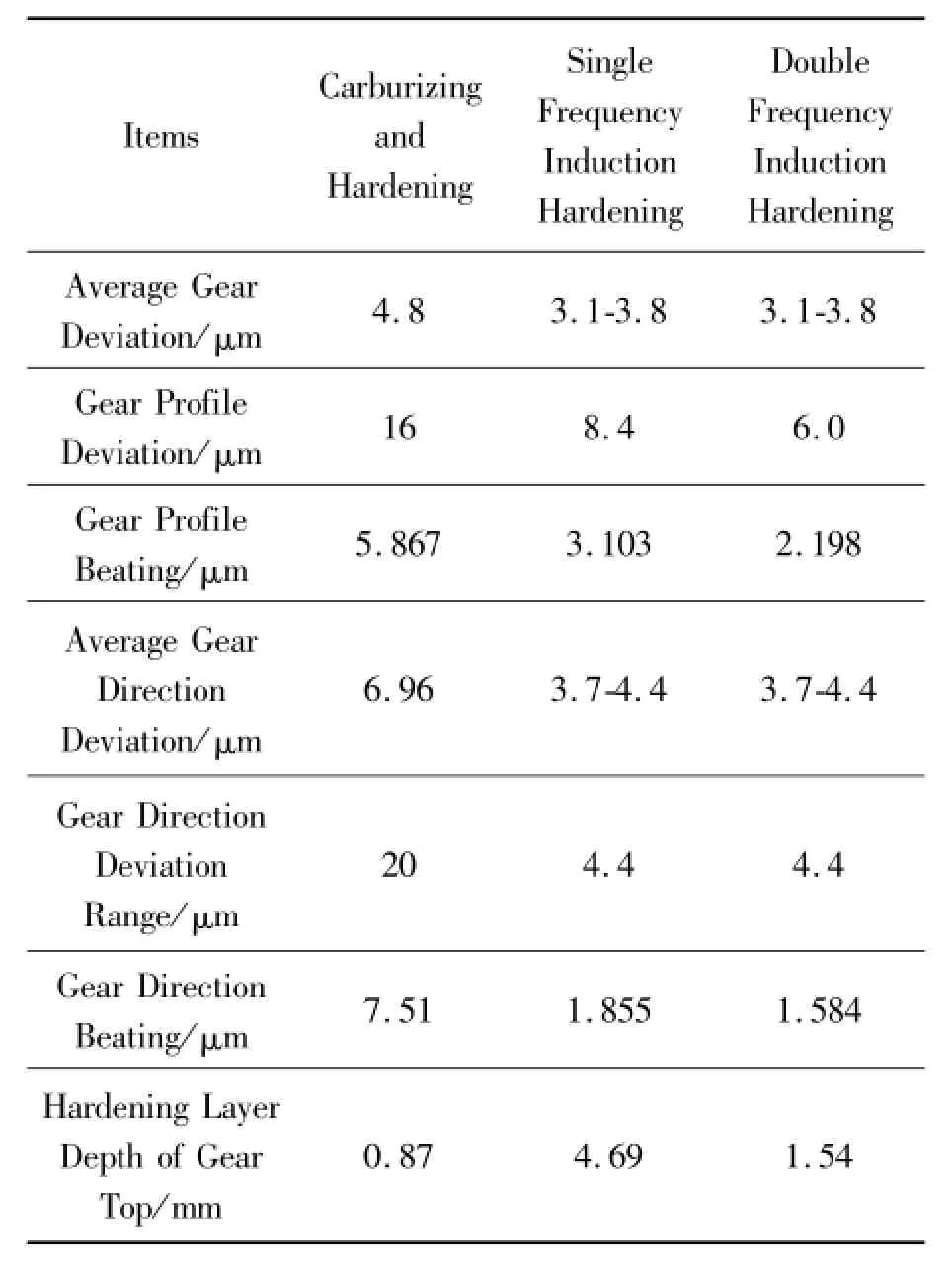
Main Parameters of Three Kinds of Induction Hardening Techniques Experiments is shown in Table 1.
4.2 Comparison of the results for these three experiments
We can see from Table 2 that the gear heat treatment after double frequency hardening will produce the smallest distortion and the highest precision.
Double frequency induction hardening could obtain a hardening layer distribution along the gear profile. As compared to single frequency(high frequency and intermediate frequency)hardening,it will produce small heat distortion,small structural distortion and small gear hardening distortion.Induction hardening obtains smaller gear distortion and deviation as comparison with carburizing hardening.

TabIe1 Three kinds of induction hardening main process parameters

TabIe2 Gear distortion test resuIts after three induction hardening
5 Synchronous double frequency induction hardening technique
Synchronous double frequency induction hardening technique is a process in which high frequency and intermediate frequency current will simultaneously output at one coil to the workpiece with a rapid heating. For example,the SDF generator outputs a HF(high frequency)current and an MF(medium frequency)current under normal power,and IGBT technology is used to add a high-frequency vibration to the intermediate frequency oscillations basis.HF and MF power elements can continuously adjust from 2%to 100%. With the help of integrated PLC control program with multiple program time and power settings,they are especially suitable for workpiece with complicated surface like gears.Also,SDF synchronous double frequency induction hardening can obtain a hardening layer distribution along the gear profile,which can partly replace carburizing process.What’s more,since the shape of bevel gear is very complex,it is very difficult to grind its teeth after carburizing in order to correct the distortion.And with the use of SDF synchronous double frequency induction hardening technique,the processing time[heating time 200 ms,power 580 kW(MF+HF),10 kHz and 230 kHz]is about only 40%of the time spent as compared with the traditional carburizing process.In addition,induction heat treatment is a kind of surface local heat hardening,so the small heat distortion can definitely meet the distortion tolerance requirement and the gear teeth do not need grinding.Currently,the power of SDF synchronous double frequency induction heat equipment can reach above 3MW,completely being able to meet the needs of surface heat treatment of medium and large gears.Fig.5 shows the synchronous double frequency induction heating of gear and the distribution of the hardening layer.
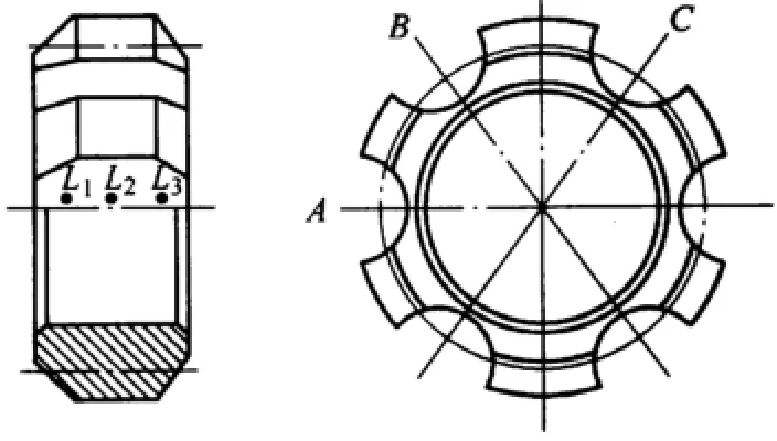
Take the planetary gear(Fig.4)as an example.It has negligible distortion after SDF synchronous double frequency induction hardening as compared to the medium frequency induction hardening.

Fig.4 PIanetary gear diagram
Fig.5 compares the amount of distortion and the depth of the hardened layer of the planetary gear at three different transverse positions A,B,C,and three different longitudinal positions L1,L2,L3.On the vertical scale,the left line represents the amount of distortion and the right line represents the depth of hardened layer.The horizontal scale indicates the position of the test point.The black dots represent the depth of hardened layer and the lines represent the amount of distortion.Obviously,SDF synchronous double frequency induction hardening produces smaller distortion and more uniform profile hardened layer.
SDF induction heating devices can also be used in the induction hardening of bevel gear,driven planetary gear,worm,rack and so on.SDF induction heating devices,such as model IGBT of the MIND series developed by Germany company ELDEC has a power range of 15-3 000kW.
Currently,SDF induction heating devices have been widely applied in parts like automotive CV joints,drive shafts,steering device,spiral bevel gear and driven planetary gear in auto-making and aerospacemanufacturing industry.Their application can also be found in German auto-maker BMW,Volkswagen and U.S.aircraft manufacturer Boeing Company.

Fig.5 The comparison of the distortion of pIanetary gear using different induction hardening techniques
6 Summary
1)When the high frequency induction current is used,its penetration depth is very small(about 0.5 mm).It could be mainly used for the surface hardening of small modulus gear.
2)When the intermediate frequency induction current is used,its penetration depth is fairly deep(5-10 mm).It could be mainly used for the surface hardening of small and medium modulus gear.
3)Double frequency induction current could be primarily used in order to obtain a uniform hardened layer distribution along the gear contour.
4)SDF synchronous double frequency induction hardening could produce smaller gear distortion and more uniform hardened layer along the gear contour. References
[1]HUA Chenliang,ZHANG Wei,WANG Fu.Discussion on the dual frequency induction hardening heat treatment process of cold roll[J].Journal of Wuhan Engineering Institute,2014(3):38-43.
[2]BaoShishu:Automobile constant velocity universal joint drive shaft assembly with different sound reasons and Countermeasures[J].Bearing,2012(1):6-8.
[3]SONG Minsheng.Analysis of tooth root cracking causes of gear induction hardening crankshaft[J].Heat Treatment,2014(4):69-71.
[4]HaoFenglin.Several factors affecting the quality of induction quenching[J].MW Metal Forming,2014(S2):128-131.
[5]ZengDehui,XieWen.The influence of the initial hardness of induction hardening depth[J].MW Metal Forming,2014(S2):180-183.
[6]ZHANG Hu;ZHANG Mingqing.Study on quenching process technology of large ring weldment surface induction[J]. Journal of Hubei University of Technology,2014(4):100-103.
[7]ZHANG Mingya.Research on intermediate frequency induction heat treatment technology of ultrafine grained dual phase steel seamless steel tube[J].Steel Pipe,2014(4):18-22.
[8]CaoDenggao.Overview of the research progress of gear production technology in China[J].China High-Tech Enterprises,2014(23):5-7.
[9]Wang Meng,WangZhong,FengXianlei,etal.Analysis of the causes of quenching crack of workpiece induction ball[J]. Machinist Metal Forming,2014(13):95-97.
[10]ChengJun,KongLingfei,ChengLiang,etal.The surface at the same time heating way to realize the high frequency induction hardening[J].Machinist Metal Forming,2014(13):97-99.
[11]DuYongchen,GongYuxia,ZhangShuting,etal.Analysis of the residual electromagnetic induction hardening crankshaft stress simulation and the fillet stress effect[J].Internal Combustion Engine&Parts,2014(6):44-47.
[12]LiDan,XueWei.Analysis of influence factors of big modulus gear induction hardening layer[J].Machinist Metal Forming,2014(11):34-35.
[13]WangMeng,WangZhong,FengXianLei,etal.The large ring gear induction heat treatment process[J].Machinist Metal Forming,2014(11):40-42.
[14]DaiQiuqi.Application and development of heat treatment technology in gear manufacture[J].Technology Innovation and Application,2014(15):80.
[15]CHEN Guo min,YAN Man gang.Comments on the gear induction hardening technology in China[J].Heat Treatment of Metals,2004(1):32-39.
齿轮单频及同步双频感应淬火工艺比较研究
金星烨1,宋广浩1,郑卫刚2*
1.武汉理工大学能源与动力工程学院,武汉 430063
2.武汉理工大学工程实训中心,武汉 430063
根据各类齿轮不同齿轮模数、形状及其淬硬层深度、硬度、显微组织,热处理畸变要求的应用范围,比较高频、中频感应淬火、双频、SDF同步双频感应淬火工艺的优缺点及其应用范围。
齿轮热处理畸变;高频淬火;中频感应淬火;同步双频感应淬火
10.3969/j.issn.1001-3881.2015.12.011Document code:A
TG162.73
15 July 2014;revised 17 February 2015;accepted 6 March 2015
*Corresponding author:Wei-gang ZHENG,Associate profes
sor.E-mail:zfeidiao@126.com
- 机床与液压的其它文章
- Research of numerical simulation on the spatial distribution of plasma antenna radiation field based on MATLAB
- Failure analysis for spindle system of CNC machine tools based on FMECA
- A valve can be designed to stabilize the gas-liquid flows
- The CNC transformation of CA6140 lathe based on motion controller
- Simulation analysis for punching machine driven by linear motor
- Application of improved PSO-based to neural network control system of parallel mechanism

