Simulation analysis for punching machine driven by linear motor
Jing LUO1*,Tie-zhong XIAO2,Juan HUANG2(1College of Mechanical Engineering,Chongqing University of Technology,Chongqing 400054,China)(2Vehicle Engineering Department,Sichuan Engineering Technical College,Deyang 618000,China)
Simulation analysis for punching machine driven by linear motor
Jing LUO1*,Tie-zhong XIAO2,Juan HUANG2
(1College of Mechanical Engineering,Chongqing University of Technology,Chongqing 400054,China)
(2Vehicle Engineering Department,Sichuan Engineering Technical College,Deyang 618000,China)
Punching machine driven by linear motor can achieve"zero drive",which has the advantages of simple structure,high control precision and low noise,so it is one important development direction of precision punching machine.Based on the design of punching machine structure driven by linear motor,dynamics simulation analysis for the simplified punching machine work process was carried out by using the ADAMS software,and then moving parts’displacement-time,speed-time,acceleration-time and press force-time curves were obtained.All these results were consistent with the design requirements.The punch direct carrying member-mold stiffness was analyzed by using HyperMesh finite element analysis software.Through the analysis,the designed mold structure can meet the requirements of stiffness.The punching machine control system was designed as well.
Linear motor,Punching machine,Dynamic simulation,Stiffness analysis,Control system
Hydromechatronics Engineering
http://jdy.qks.cqut.edu.cn
E-mail:jdygcyw@126.com
1 Introduction
Linear motors are more and more widely used,which has the advantages of fast response,large velocity and acceleration,high positioning accuracy,simple structure,high transmission efficiency,no mechanical wear,etc[1-2].Punching machine driven by linear motor has the following advantages as compared with traditional punch[3-4]:①a high precision of molding process ability;②Low noise and small vibration;③Energy conservation;④meet the requirements of clean environment;⑤ease of online production;⑥intelligent processing method,easy to operate etc.Therefore,the punching machine driven by linear motor is an important development future direction of precision stamping machine[5-6].Based on the design of punching machine structure driven by linear motor,machine kinematics,dynamics and bearing components stiffness were analyzed by using ADAMS,HyperMesh and other software.The reasonableness of the machine design was verified.And machine control system was designed by using the programmable logic controller PLC.
2 Working principle of punching machine
Punching machine driven by linear motor was designed in this paper,as shown in Fig.1.Punch utilized vertical structure,a cylindrical linear motor driver replaced with traditional"rotary motor+crank rod"drive form,then mechanical structure of the pumping machine was simplified and the dynamic response performance was improved.Its working cycle was:the use of electromagnetic force generated by the moved air gap magnetic field,Driven mold bases are accelerated downward movement guided by cylindrical Ball Rail.After the mold bases is moved 40 mm(exercise time 0.078 s),punch a workpiece at a speed of 1.03 m/s,punching time was less than 1ms.And then the mold bases will be accelerated upward under the action of electromagnetic force and be decelerated back to the initial position by using self-gravity,and the exercise time was about 0.221 s,a punching processing was completed.

Fig.1 Punching machine driven by Iinear motor
3 ADAMS dynamics simulation analysis
Core mechanical system simulation technology is multi-body dynamics theory,multi-body dynamics can be divided into two sections of multi-body dynamics and multi-flexible system[7].The Research object of Multi-body dynamics is the multi-body system with a finite number of rigid bodies connected by a constraint composition,so the research object of this paper is multi-body dynamics problems.Researching multibody dynamics,it first needs analyze the system of motion equations,and then solves system constraint equations by bringing into constraint conditions;body motion parameters and related physical quantities expressions were obtained[8].
3.1 Import model and add constraints
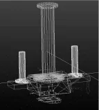
Punching machine model must be established before simulation analysis.A Three-dimensional solid model was established in UG,and then the analysis model was established through analysis method by using ADAMS software[9].To facilitate analysis,machine model was simplified,and only the moving parts of punching machine are left,the simplified model which will be imported into the ADAMS as shown in Fig.2.
After introducing a simplified model as shown in Fig.2,first constraint for each entity,add fixed deputy among cylindrical rail,the spring mount,butterfly spring and mold bases,add fixed deputy between Linear motor secondary and butterfly spring.Add motion deputy Completion of the aforementioned geometric constraints,that is to say add movement deputy between the two cylindrical rails.

Fig.2 ADAMS anaIysis modeI
3.2 Dynamics simulation analysis
Punching cycle of punching machine was 0.3s,that was 200times/min.At work,punch did downward movement in the action of downward electromagnetic force and gravity,movement time was 0.078s,motion displacement was 40 mm,then punch parts,punching time was 1ms.Finally,punch accelerated upward under the action of electromagnetic force and then decelerated back to the initial position under gravity,movement time was 0.221s.
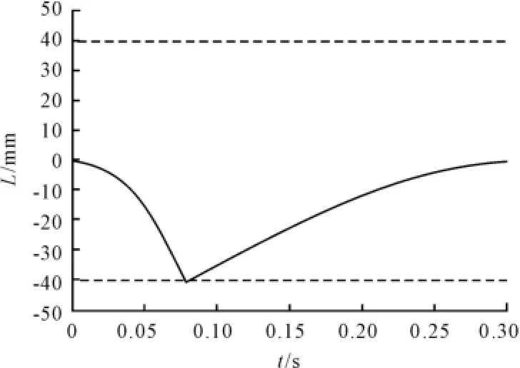
In order to analyze,the bottom mold contacted with the workpiece,the quality of the secondary motor needs to be considered when the load is applied,so the applied load function on the motor secondary,IF(time-0.078:(1.03×1 000/0.078-9 806.65)× 42.396/1 000,0,IF(time-0.079:0,0,IF(time -0.279 6:-588,0,0))),simulation time was 0.3s,step was 3 000 steps,the model after loading was shown in Fig.3.Click the Start button on its motion simulation,using ADAMS post-processing capabilities,the obtain results were shown in Figs.4-7.

Fig.3 ADAMS Ioading modeI

Fig.4 DispIacement-time curve

Fig.5 Speed-time curve

Fig.6 AcceIeration-time curve

Fig.7 Pressforce-time curve
Through the simulation results,the speed-time curve,displacement-time curve and accelerationtime curves were consistent with those of theoretical calculations.As shown in Fig.7,the maximum press force was about 52kN,which is greater than the actual requirements value of the 40kN,namely the simulation results could meet the requirements of nominal power punch.In summary,machine could meet the dynamics design requirements.
4 Stiffness analysis of mold
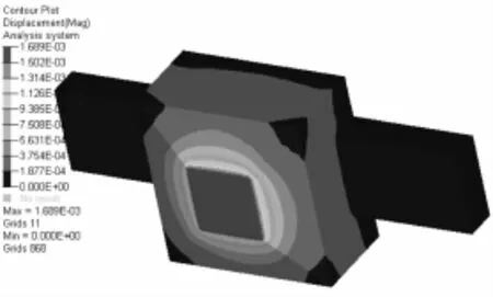
Mold was directly forced parts of the punching machine by moving sections,whose stiffness could directly determine the quality of punching machine,so the stiffness of the mold must meet the requirements of the force deformation.Mold’s material was 45 steel,its parameters were:elastic modulus E=210 GPa,Poisson's ratio μ=0.27,density ρ=7 890kg/m3.In order to analyze,add zero displacement constraints at the upper end of the mold,and apply the punching machine mold nominal force 40kN at the lower end of the mold,the analysis results were shown in Fig.8.

Fig.8 MoId deformation stiffness nephogram
As shown in Fig.8,the maximum deformation amount was 1.689×10⁻³mm,which appeared on the lowermost plane of the mold,and the result was consistent with theoretical design requirements.
5 Control system design
5.1 Control program design
Control system used a combination method of speed adjustment and current regulation for controlling punching machine.Specifically,the speed adjustment could control the position of the linear motor,efficiency and stability of the whole control system;the current regulation could control the limited magnitude about linear motor startup and a wide range of acceleration and deceleration.Through structural analysis,the actual numerical calculation and punching process simulation analysis,the punch has a large kinetic energy when punching a workpiece.Speed adjustment,current regulation was assurance of punching up and downward stroke position degrees,the speed and acceleration of linear motors and other key technologies. Control program will directly determine whether these above-mentioned key technologies to achieve accurately or not.Through comparative analysis,the control program was designed as shown in Fig.9.

Fig.9 ControI program
At the downward stroke,the speed adjustment of control system used the open-loop control,by setting the voltage value(the desired speed corresponding to the voltage value when processing)and the acceleration time of the PLC system to control the speed of the punching machine.At the same time punching position was controlled by setting a lower row value of PLC system.Current is regulated by using a closed-loop control,the current regulator output signal controlls the linear motor drive output voltage,so that the drive could use the correct voltage to drive linear motors,online detected the current value and fed back to the current regulation to realize closed-loop control of current regulation.The movement of the downward stroke was properly completed by adjusting the speed and current control,and vice versa for the upward stroke.
5.2 The downward stroke control system design
The main task of the downward stroke control was to achieve accurate positioning of the punch and get enough instantaneous speed,and the author adopted PLC control system to design punch control system.It showed that the downward stroke displacement was 40mm,the acceleration time was 0.078 s and the acceleration was 13.3 m/s2through a series of analyses including structural analysis,data collection,theoretical calculations and the stamping process simulation.
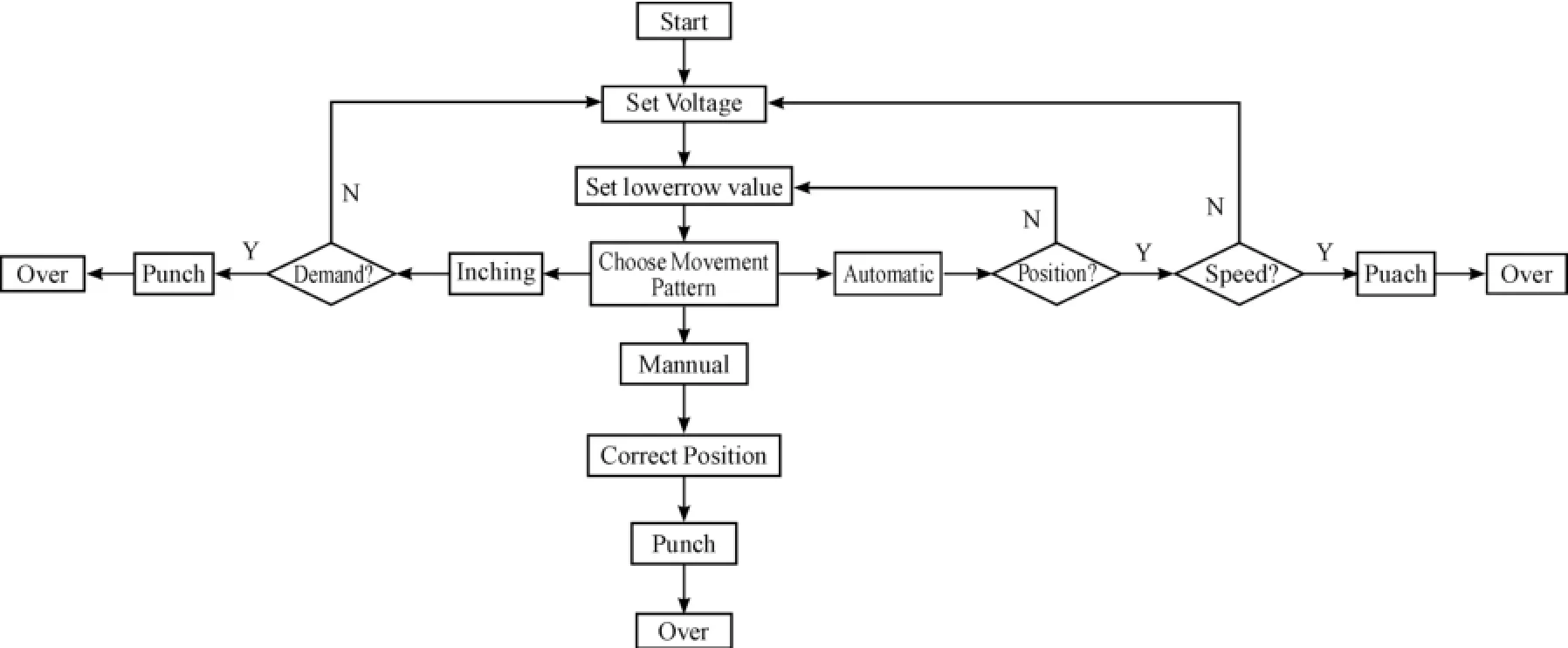
Fig.10 was a flowchart of the downward stroke control,the setting voltage value in flowchart corresponded to the operating speed of linear motor,and the lower row values corresponded to the downstream position of linear motor,mutually combination of both can effectively ensure pumping quality.Voltage value and the lower row values were set by the PLC program. The electrical connection of downward PLC control system was as shown in Fig.11 and Fig.12.In order to ensure the safety of the operation process,emergency stop switch was designed,when there was an emergency,pressing the emergency stop switch can stop punching machine immediately.The upward stroke of the control system can be obtained similarly.

Fig.10 DownIoad stroke controI fIowchart

Fig.11 PLC controI of eIectricaI connection

Fig.12 EIectricaI connection of Iinear motor drives
6 Conclusions
1)Working principle of punching machine driven by linear motor was elaborated,and some of its parameters were described;
2)Three-dimensional model of punching machine was established by UG,dynamics simulation analysis for the simplified punching machine work process was carried out by using ADAMS software,and then the moving parts’displacement-time,speed-time,acceleration-time and pressforce-time curves were obtained. These four curves were consistent with the theoretical value,namely the design punching machine could meet the dynamic design requirements.
3)The punching machine direct carrying membermold stiffness was analyzed by using HyperMesh finite element analysis software.Through analyzing,the obtained mold stiffness deformation nephogram and the designed mold structure can meet the requirements of stiffness.
4)On the basis of the theoretical analysis calculation of pumping process and motion simulation using ADAMS,the punching machine control system was designed.
Acknowledgements
This paper is supported by Scientific and Technological Research Program of Chongqing Municipal Education Commission(No.KJ130806).
[1]WANG Huiyong,MAN Zhonglei,LI Xiangnan,etal.Development tendency and application of linear motor in manufacturing industry[J].Machines&Control Application,2013,40(3):1-4.
[2]Zhang Qian,Wan libin,Zhao Tong.Application of Linear Motor in High-End NC Machine Tool[J].Aeronautical Manufacturing Technology,2013(05):52-54.
[3]Tang Lichan,Qi Liang,Wang Qingdong.Application of domestic linear motor in the machine tool[J].Machinery and equipment,2010(1):8-14.
[4]JIANG Chaoxia.Application of linear motor in CNC lathe[J].Manufacturing Technology&Machine,2008(4):62-64.
[5]YANG Jian-fei,HU Yu-wen,HUANG Wen-xin,etal.Application of direct driving technology in press[J].Micromotor,2008,41(10):65-72.
[6]Zhang Chunliang,Chen Zichen,Mei Deqing.Present Status and Developing Trend of Linear Motor Direct Drives[J]. Agricultural Machinery,2002,33(05):119-123.
[7]Chen Lesheng,Wang Yilun.Multi-body dynamics foundation[M].Harbin:Harbin Engineering University Press,1995.
[8]Yang Binjiu.Study on some problems in constraint chain of no-full DOF parallel machine tool[D].Shenyang:Northeastern University,2006.
[9]HOU Hongling,ZHAO Yongqiang.Kinematics analysis based on ADAMS&ANSYS[J].Mechanical Design&Manufacturing,2010(5):75-77.
直线电机驱动的冲压机床仿真、分析与控制研究
罗 静1*,肖铁忠2,黄 娟2
1.重庆理工大学机械工程学院,重庆 400054
2.四川工程职业技术学院车辆工程系,四川德阳 618000
直线电机直接驱动的冲压机床具有“零传动”、无机械磨损、响应快、结构简单等特点,是精密冲压机床的重要发展方向之一。在设计直线电机驱动的冲压机床结构的基础上,利用ADAMS软件对简化后的冲床的工作过程进行了动力学仿真分析,得到了运动部件位移-时间、速度-时间、加速度-时间及冲压力-时间等曲线,其结果均与设计要求吻合;然后利用HyperMesh有限元软件分析了冲床直接承载部件-模架的刚度,通过分析可知:设计的模架结构满足刚度使用要求;最后设计了冲压机床的控制系统。
直线电机;冲床;动力学仿真;刚度分析;控制系统
10.3969/j.issn.1001-3881.2015.12.017Document code:A
TH122
1 August 2014;revised 2 December 2014;accepted 1 March 2015
*Corresponding author:Jing LUO,Professor.
E-mail:luojing@cqut.edu.cn
- 机床与液压的其它文章
- Research of numerical simulation on the spatial distribution of plasma antenna radiation field based on MATLAB
- Failure analysis for spindle system of CNC machine tools based on FMECA
- A valve can be designed to stabilize the gas-liquid flows
- The CNC transformation of CA6140 lathe based on motion controller
- Application of improved PSO-based to neural network control system of parallel mechanism
- Dynamic parameters identification withconsidering hyper-viscoelasticof rubber bushing

