Thrust producing mechanisms in ray-inspired underwater vehicle propulsion
Geng Liu,Yan Ren,Jianzhong Zhu,Hilary Bart-Smith,Haibo Dong
Department of Mechanical and Aerospace Engineering,University of Virginia,Charlottesville,VA 22904,USA
Thrust producing mechanisms in ray-inspired underwater vehicle propulsion
Geng Liu,Yan Ren,Jianzhong Zhu,Hilary Bart-Smith,Haibo Dong∗
Department of Mechanical and Aerospace Engineering,University of Virginia,Charlottesville,VA 22904,USA
A R T I C L E I N F O
Article history:
Received 24 November 2014
Accepted 26 November 2014
Available online 6 January 2015
Hydrodynamics
Bio-inspired autonomous underwater vehicle
Computational fluid dynamics
Vortex dynamics
This paper describes a computational study of the hydrodynamics of a ray-inspired underwater vehicle conducted concurrently with experimental measurements.High-resolution stereo-videos of the vehicle's fin motions during steady swimming are obtained and used as a foundation for developing a high fidelity geometrical model of the oscillatory fin.A Cartesian grid based immersed boundary solver is used to examine the flow fields produced due to these complex artificial pectoral fin kinematics.Simulations are carried out at a smaller Reynolds number in order to examine the hydrodynamic performance and understand the resultant wake topology.Results show that the vehicle's fins experience large spanwise inflexion of the distal part as well as moderate chordwise pitching during the oscillatory motion.Most thrustforce is generated by the distalpartofthe fin,and it is highly correlated with the spanwise inflexion. Two sets ofinter-connected vortex rings are observed in the wake rightbehind each fin.Those vortex rings induce strong backward flow jets which are mainly responsible for the fin thrust generation.
©2015 The Authors.Published by Elsevier Ltd on behalf of The Chinese Society of Theoretical and Applied Mechanics.This is an open access article under the CC BY-NC-ND license(http:// creativecommons.org/licenses/by-nc-nd/4.0/).
A bio-inspired autonomous underwater vehicle(AUV)has been designed as a scientific platform to understand the superior swimming characteristics of batoid fish.Batoid fish such as manta rays(Manta birostris)and cownose rays(Rhinoptera bonasus)are notable for their fast,efficient swimming and high maneuverability.These swimming capabilities arise from flapping of the dorsally flattened pectoral fins,which are also used as control surfaces for depth control and maneuvering.Recent observations in animal propulsion suggest that high efficiency in animal locomotion can be attributed to the stiffness characteristics at the fin tip[1].In rays'swimming,the large bending of the distal part of the pectoral fin can allow them to actively resist hydrodynamic bending forces while producing propulsion forces.To assess this contribution,the current effort is specifically focused on understanding the hydrodynamics of a ray-inspired underwater vehicle -the MantaBot-where biology is the basis for the design.
The MantaBot consists of two parts:a rigid body rendered from a computer tomography scanning image of a cownose ray and a pair of soft fins driven by tensegrity-based actuators[2](Fig.1(a)). The soft fins of this vehicle are highly flexible,have complex planforms,and undergo an oscillatory motion.Specific to this vehicle's body length(L~43 cm)and free-swimming velocity(0.35 m·s-1),the Reynolds number(Re=UL/ν)is approximately 1.5×10⁵. At this Reynolds number,the attached flow over the body is most likely laminar but transition to turbulence is expected to occur rapidly in the downstream of MantaBot fins.The flow over the fins can be characterized in terms of a Stokes frequency parameter(S=ωAc/ν)whereω,A and c are the fin angular frequency,amplitude and length of the mid-chord,respectively.Typical fin beat frequency of about 2 Hz and fin amplitude and size of about 5 cm and 6 cm,respectively,give S≈3.5×10⁴,which is again in the range where transition from laminar attached flow to turbulence will occur quickly.
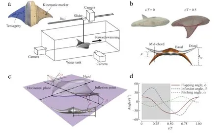
Figure 1(a)shows the MantaBot body with kinematic markers(red dots)drawn on its fins,which are used for tracking and performing 3D surface reconstruction later in the process and a schematic of the experimental setup.To measure the fin kinematics of MantaBot in steady swimming,the vehicle is placed in a 5 m long,1.5 m wide,and 0.6 m deep water tank.Its locomotion is restricted to one degree of freedom(forward translation)using a steel bar,which is connected to a low-friction ball bearing slider on a linear rail.
The MantaBot swimming motion is then recorded by three well calibrated and synchronized video cameras(rear,side,and top)that are operated at 60 Hz with 512×512 pixel resolutions.These cameras are aligned orthogonalto each other and positioned about 0.75 maway from the Mantabot,giving a depth offield of3-4 body lengths in all directions.The cameras are triggered by a flashing lightsystemto minimize the recording delay ofeach camera.When the MantaBotis in the optimumrange,this camera systemisable to collect data that is consistently in focus.Usable segments of videos from all sides are identified for kinematics reconstruction based on the quality of images.Among all three cameras,the camera set at the rear is for recording the fin flapping motion and spanwise bending.The videos from this camera are used to measure both the flapping angles and inflexion angles shown in Fig.1(c).The side camera,along with the top camera,is used to track the motions of all kinematic markers in Fig.1(a).They are used to accurately measure the chordwise flexibility including the mid-chord pitching angles in Fig.1(c).
Once these videos are identified,a marker-based 3D surface reconstruction method[3]will then be used to obtain the instantaneous control surfaces of the flapping MantaBot during the steady swimming.These reconstructed 3D surfaces will be meshed using triangular grids and used as inputs for later computationalfluid dynamics(CFD)simulations.Details about this method can be found in Ref.[3].
A number of combinations of driving frequency and amplitude of the MantaBot were tested,and the case that achieved the maximum speed was selected for this study.Key quantities of the body shape and locomotion are summarized in Table 1,where L is the body length,l is the fin span length,U is the swimming speed,A is the flapping amplitude of the fin mid-chord,f is the flapping frequency,St is the Strouhal number defined as St=fA/U,and Re is the Reynolds number.
The reconstruction model is shown in Fig.1(b).Upper two plots are the side view of the original MantaBot and the meshed model in 3D reconstruction at the beginning of downstroke and upstroke,respectively.The lower plot is the front view of the model showing the maximum fin bending.The most apparent feature from the fin kinematic reconstruction is the spanwise flapping with large bending at distal part.As shown in Fig.1(c),the flapping angleφ is the angle between the base-to-tip line and the horizontal plane,where the fin base is 0.33l away from middle section of the body. The spanwise bending can be quantified by inflexion angle(β)[1]. The maximum bending happens mostly at 0.67l from the fin base. This location is defined as the inflexion pointshown in Fig.1(c).βis the angle between the lines ofbase-to-inflexionpoint and inflexion point-to-tip.The pitching angleαin Fig.1(c)is defined as the angle between the chord at inflexion point and the horizontal plane.
Figure 1(d)shows the time course ofφ,β,andα,which are averaged over four consecutive flapping strokes from meshed fin models.The time variation ofφindicates that the basic fin flapping motion is not symmetric.The downward excursion is more than twice the upward excursion.Spanwise bending is prominent because the inflexion angleβhas larger peak-to-peak amplitude values among all three angles.The maximum amplitude ofβis about 45°,which is slightly larger than the average inflexion angle observed in most swimming and flying animals[1].This indicates that the MantaBot fins can achieve large amplitude of bending of the distal parts.The chordwise pitching is observed varying in between±16°during this steady swimming motion.It is worth noting that the tensegrity actuation structures in the MantaBot cannot generate chordwise pitching directly.The fin pitching is passively generated by the interaction between the surrounding flows and the soft fins.It is also found that this pitching motion can only be clearly observed in the distal part of the fin.

Fig.1.(a)MantaBot with tensegrity actuator and kinematic markers and experimental measurement setup.(b)Side views of original MantaBot(upper left)and meshed model(upper right)and a front view of the MantaBot model(lower)at t/T=0 and t/T=0.5.(c)Definition for flapping,inflexion and pitching angles(φ,βandα,respectively).(d)The time course of the measured kinematics in one typical flapping cycle.

Table 1Key quantities of the body shape and swimming motion.
The hydrodynamic mechanism of the ray-inspired underwater vehicle propulsion is then explored using an immersed boundary method[4]based high fidelity CFD simulation.In particular,the solver is time-accurate and non-dissipative,and allows body motion.The details of the solver can be found elsewhere[5-7].To study the long-term hydrodynamic performance of the flapping fins in steady swimming,a uniform flow of speed U passing the MantaBot modelis utilized to save on computation cost.The goalof current simulations is to capture the key features ofthe wake structures for addressing the fundamental hydrodynamic mechanisms ofthe flapping swimming.To this end,the actual Reynolds number is reduced to 1200 for meeting the requirement ofthe mesh resolution and computation costby directnumericalsimulation ofswimming objects[8-12].This is equivalentto either a smaller size bodyperforming a similar motion or using the same body performing a slower motion[12].The nominal grid size employed in the simulations is 264×178×264,which gives approximately 12.4 million grid points in total.Comprehensive studies have been carried out to assess the effectofgrid resolution and domain size on the salient features of the flow,and to demonstrate the accuracy of nominal grid size.According to the stability requirements of the flow solver,time step is chosen to be T/480,where T is the period ofthe flapping motion.For a completed simulation of the MantaBot flow reaching to the steady state using a 10-6convergence criteria for velocity,92 CPU hours on a single Intel(R)Core(TM)i7-3770 CPU @3.4 GHz computer node are generally needed.Results presented here have been obtained by simulating the flow over six fin strokes. The hydrodynamic forces producedby the fin during the stroke will be discussed first,followed by a description of the instantaneous vortex structures formed during the fin strokes in order to elucidate the flow mechanisms responsible for force production.

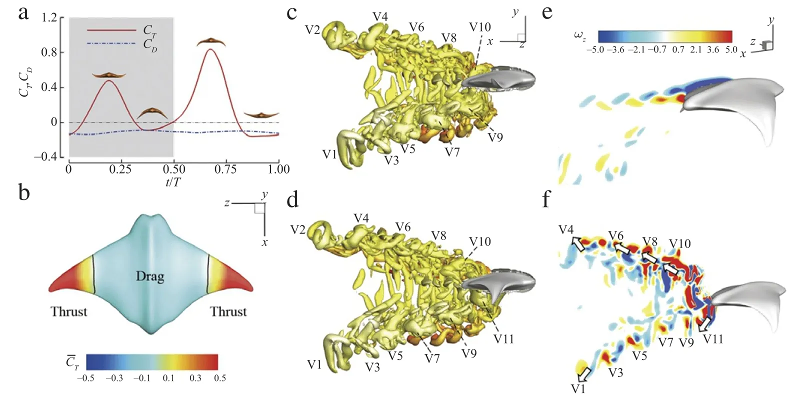
First,it is noted that both downstroke and upstroke produces peaks in thrust force.The peak in the upstroke is about 0.84,which is 1.75 times the peak in the downstroke.This matches with the findings in real ray swimming by Heine[14]that upstrokes should play a more important role in thrust producing than that in downstrokes.This may be attributed to both geometric and kinematic asymmetry between the dorsal and the ventral side of the fin.
Second,the thrust is highly correlated with the inflexion by comparing Fig.1(d)with Fig.2(a).The peaks in CTappear at the same moments asβandαexhibit peak/trough values.Moreover,a negative CTwhich means pressure drag always located at/near the time of zeroβandα.Noting that pitching motion is purely passive and is dependent on the inflexion angle in this case,the thrust production is mainly correlated with the inflexion angle.
The cycle-averaged value of CTis 0.15,which is slightly higher than the absolute value of cycle-averaged CD(0.11).This is reasonable even though the MantaBot was observed performing steady swimming.The MantaBot only has one degree of freedom while the other five degrees are restrained by the rail(shown in Fig.1(a)).Therefore,the MantaBot has to generate extra thrust to overcome the friction force between the slider and the rail.


Fig.2.Simulation results ofthe modeled MantaBotatReynolds number1200.(a)The time history ofthrustand drag coefficients atthe fifth flapping cycle.(b)Distribution of cycle-averaged thrust coefficients on the body surface.(c),(d)Side views of the iso-surface contours of the wake topology at t/T=0.19(c)and t/T=0.63(d)(performance peaks in(a)).The vortex structure is identified by Q-criterion at Q=1.0,and colored by the distance from the mid-plane of the body,where yellow represents near the body and red represents away from the body.(e),(f)Contours of the instantaneous spanwise vorticityωzon the sectional slices at 0.30l(e)and 0.95l(f)from the fin root when t/T=0.63.(For interpretation of the references to color in this figure legend,the reader is referred to the web version of this article.)

Table 2Mean values and root-mean-square deviations of thrust and drag coefficients.

To further understand the thrust producing mechanism of the MantaBot fins,wake topology and vortex dynamics are investigated.Figures 2(c)and 2(d)highlight two snapshots of the 3D flow fields when fins reach to peak thrust in the downstroke and the upstroke respectively.The isosurfaces of Q-criteria are used to identify the wake topologies.During each downstroke or upstroke,there is a vortex ring shed from the trailing edge of the fin.These vortex rings are labeled from V1 to V11 following the shedding order.For instance,V1 is the earliest shed vortex ring in the plots while V11 is the latest.In addition,some smaller vortex structures(in red),which are further away from the bodythan those labeled vortex rings,can also be observed.In the sixth flapping cycle,the downstream wake mainly consists of two sets ofcomplex shaped vortex rings,which convect at oblique angles to the wake centerline.Those vortex rings are inclined with respectto the free stream.It is also noted that there are a number of vortex contrails that extend towards the two adjacent counter-rotating rings.As the vortices convect downstream,these contrails become weaker and ultimately disappear(as for vortex ring V1),leaving only fairly well-defined vortex rings.The overall characteristics of the wake structure are similar to that of a pitching-plunging plate[15].
The time instance shown in Fig.2(d)is half a cycle later than that shown in Fig.2(c).It is worth noting that the shapes of vortex rings far away from the body(V1-V6)do not change much during the half cycle,while the shapes of vortex rings near the body(V9 and V10)change significantly.For instance,V9 has a groove on the surface in Fig.2(c).After half a cycle,the groove stretches and separates away from V9,further forming a hairpin-like vortex structure with the two legs still connecting with V9(see Fig.2(d)). This hairpin-like vortex structure will be totally detached from V9 and forms a new vortex ring as the one near V7 shown in Fig.2(d).
To better understand the flow induced by the 3D vortex structures,two vertical slices are used to show the contour of spanwise vorticityωzat the basal part and distal part of the fin,respectively.Avon Kármán vortex street,which is a drag producing vortex structure,is found on the slice at the basal part(0.3l away from the fin base,see Fig.2(e)).However,due to the large flapping amplitude in the distal parts,effective Strouhal number is increased to 1.1 based on Atip.This is about four times of the mid-chord Strouhal number,which is measured 0.27 based on the flapping amplitude of the fin mid-chord,A.Thus,at 0.95l(Fig.2(f)),there are two sets of vortex pairs aligned at oblique angles to the wake centerline.This is the same as the wake topology of vortex rings shown in Fig.2(c).Each vortex pair will induce a strong local jet.The orientation of the jets induced by some of the vortex pairs is identified by arrows in Fig.2(f).These jets are mainly responsible for the thrust producing of the fins.It should be noted that the upper set of vortex pairs are much stronger than corresponding lower vortex pairs.This explains why the thrust generated during upstroke is larger than that generated during downstroke.
In summary,the double vortex ring loops shed from the distal part of the MantaBot fins are responsible for thrust production of the propulsors.The large inflexion angle of the oscillatory fin not only helps the fin distal parts to achieve a higher effective Strouhal number for thrust production but also allows the fin basal parts to maintain minimum flapping amplitude,which results in a small amount of drag during the MantaBot's steady swimming.
Acknowledgment
This work was supported by the Office of Naval Research(ONR)(N00014-14-1-0533 and N00014-08-1-0642).H.Bart-Smith would like to acknowledge The David and Lucille Packard Foundation.
[1]K.N.Lucas,N.Johnson,W.T.Beaulieu,E.Cathcart,G.Tirrell,S.P.Colin,B.J. Gemmell,J.O.Dabiri,J.H.Costello,Bending rules for animal propulsion,Nature Commun.5(2014)3293.
[2]K.Moored,T.Kemp,N.Houle,H.Bart-Smith,Analytical predictions,optimization,and design of a tensegrity-based artificial pectoral fin,Int.J. Solids Struct.48(2011)3142-3159.
[3]C.Koehler,Z.Liang,Z.Gaston,H.Wan,H.Dong,3D reconstruction and analysis of wing deformation in free-flying dragonflies,J.Exp.Biol.215(2012)3018-3027.
[4]M.Bozkurttas,R.Mittal,H.Dong,G.Lauder,P.Madden,Low-dimensional models and performance scaling of a highly deformable fish pectoral fin,J.Fluid Mech.631(2009)311-342.
[5]H.Dong,M.Bozkurttas,R.Mittal,P.Madden,G.Lauder,Computational modelling and analysis of the hydrodynamics of a highly deformable fish pectoral fin,J.Fluid Mech.645(2010)345-373.
[6]H.Dong,C.Koehler,Z.Liang,H.Wan,Z.Gaston,An integrated analysis of a dragonfly in free flight,in:40th AIAA Fluid Dynamics Conference and Exhibit,AIAA,Chicago,Illinois,2010,pp.2010-4390.
[7]Z.Liang,H.Dong,M.Wei,Computational analysis of hovering hummingbird flight,in:48th AIAA Aerospace Sciences Meeting Including the New Horizons Forumand Aerospace Exposition,AIAA,Orlando,Florida,2010,pp.2010-2555.
[8]J.Carling,T.Williams,G.Bowtell,Self-propelled anguilliform swimming: simultaneous solution of the two-dimensional Navier-Stokes equations and Newton's laws of motion,J.Exp.Biol.201(1998)3143-3166.
[9]S.Kern,P.Koumoutsakos,Simulations of optimized anguilliform swimming,J.Exp.Biol.209(2006)4841-4857.
[10]G.J.Dong,X.Y.Lu,Characteristics of flow over traveling wavy foils in a side-byside arrangement,Phys.Fluids 19(2007)057107.1994-present.
[11]S.Wang,X.Zhang,G.He,Numerical simulation of a three-dimensional fishlike body swimming with finlets,Commun.Comput.Phys.11(4)(2012)1323-1333.
[12]I.Borazjani,F.Sotiropoulos,E.D.Tytell,G.V.Lauder,Hydrodynamics of the bluegill sunfish C-start escape response:three-dimensional simulations and comparison with experimental data,J.Exp.Biol.215(2012)671-684.
[13]R.Ghias,R.Mittal,H.Dong,A sharp interface immersed boundary method for compressible viscous flows,J.Comput.Phys.225(2007)528-553.
[14]C.Heine,Mechanics of flapping fin locomotion in the cownose ray(Ph.D. dissertation),Duke University,Durham,1992.
[15]H.Dong,R.Mittal,F.Najjar,Wake topology and hydrodynamic performance of low-aspect-ratio flapping foils,J.Fluid Mech.566(2006)309-344.
∗Corresponding author.
E-mail address:haibo.dong@virginia.edu(H.Dong).
*This article belongs to the Fluid Mechanics
 Theoretical & Applied Mechanics Letters2015年1期
- Theoretical & Applied Mechanics Letters的其它文章
- Adjoint-based optimization of flapping plates hinged with a trailing-edge flap
- Numerical simulation of unsteady flows over a slow-flying bat
- Propulsive performance of two-and three-dimensional flapping flexible plates
- Learning from bat:Aerodynamics of actively morphing wing
- A coupled immersed boundary-lattice Boltzmann method and its simulation for biomimetic problems
- A modified criterion for wave-induced momentary liquefaction of sandy seabed
