
Enhanced heat transfer in a heat exchanger square-duct with discrete V- finned tape inserts☆
2015-11-13 02:32WatcharinNoothongSupattarachaiSuwannapanChinarukThianpongPongjetPromvonge
Watcharin Noothong,Supattarachai Suwannapan,Chinaruk Thianpong,Pongjet Promvonge*
Department of Mechanical Engineering,Faculty of Engineering,King Mongkut's Institute of Technology Ladkrabang,Bangkok 10520,Thailand
Keywords:
A B S T R A C T
1.Introduction
Many engineering techniques have been devised for enhancing the rate of convective heat transfer from the wall surface in order to increase heat transfer rate so that compact heat exchangers with high efficiency can be developed.The uses of turbulators such as fin,baffle,rib,twisted tape,wire coil,etc.,are proved effective due to the increased turbulence degree and pressure loss.Therefore,to achieve optimal thermal performance,the pertinent con figuration parameters of the turbulator are to be considered.
Several efforts have been made to study the effect of the parameters of turbulators on heat transfer and friction factor behaviors.Promvonge et al.[1,2]investigated experimentally and numerically the turbulent flowover30°angle- finned tapes inserted in a square channel.Promvonge et al.[3-6]and Kwankaomeng and Promvonge[7]studied numerically the heat transfer of laminar and turbulent flows in a square channel and found that a pair of counter-rotating vortices(P-vortex)created by the baffles/ribs placed on the channel walls can help induce impingement/reattachment flows on the wall resulting in greater increase in heat transfer due to vortex-induced impingement(VI)effect.Eiamsaard et al.[8]reported the effects of insertion of tandem wire coil elements used as a turbulator in a square duct and found that the full-length wire coil provides higher heat transfer and friction factor than the tandem wire coil elements.Eiamsa-ard et al.[9]investigated the influence of combined circular-ring and twisted tape inserts on thermal characteristics in a round tube and reported that the combined devices provided considerably higher thermal performance than the ring acting alone.Eiamsa-ard et al.[10,11]again examined heat transfer characteristics in a circular tube with helical and twisted tapes inserted.They observed that the enhancement efficiency of the short-length tape insert was lower than the full-length one and the Nusselt number values of the loose- fit,helical tape with and without core-rod were a bout 230%and340%,respectively,over the smooth tube.Eiamsa-ard and Promvonge[12]studied experimentally thermal behaviors of turbulent tube flow through a straight tape with double-sided delta wings.They found that the delta-winged tape yielded Nusselt number and friction factor up to 165%and 14.8 times above the plain tube.Promvonge et al.[13],Chompookham etal.[14]and Thianpong et al.[15]examined the effects of ribs and winglet type vortex generators(WVGs)on heat transfer in a channel and reported that the Nusselt number and the friction factor for utilizing both the rib and the WVGs are found to be considerably higher than those for using the rib or the WVGs alone.Skullong and Promvonge[16]investigated the heat transfer and flow friction characteristics in a solar air heater channel fitted with delta-winglet type vortex generators.Sri Harsha et al.[17]and Gupta et al.[18]studied the local heat transfer distribution and pressure drop in a square channel and found that the 60°V-broken rib gives the heat transfer higher than the 90°continuous and pro filed ones.Tanda[19]investigated the effect of transverse,angled ribs,discrete,angled discrete ribs,V-shaped,V-shaped broken and parallel broken ribs on heat transfer and flow friction.Chandra et al.[20]carried out measurements on heat transfer and pressure loss in a square channel with continuous ribs on four walls and reported that the heat transfer augmentation increased with the rise in the number of ribbed walls.Murata and Mochizuki[21]studied numerically the heat transfer distribution in a rib-roughened duct with transverse or angled ribs.The comparison between the laminar and turbulent results showed clear differences in heat transfer distribution because the higher momentum fluid of the turbulent case was more disturbed by the ribs as compared to the laminar case.Han et al.[22,23]examined experimentally the heat transfer in a square channel with ribs on two walls for nine different rib con figurations.Lau et al.[24]presented the effects of V-shaped rib arrays on turbulent heat transfer and flow friction in a square channel.
Most of the literature review reports both turbulator and vortex generator in different shapes and arrangements placed only on the test section wall.The study on thermal performance of a heat exchanger square-duct with diagonal discrete V- finned tapes(DFT)inserts has never been reported.Therefore,a new DFT insert is proposed to provide higher thermal performance than wire-coil/twisted-tape inserts.The concept of this work came from another work of the authors[3]that the discrete ribs/ fins were repeatedly placed on two opposite walls of a square duct while in the present work,the discrete V- fins were mounted periodically on a straight tape for ease of insertion.Thus,the main aim of the present work is to investigate the heat transfer and flow friction characteristics in a square duct heat exchanger fitted with the DFT.The experimental data are presented for turbulent duct flows over the DFT.The use of DFT inserts is expected to create vortex flows throughout the test duct to higher mixing of flows between the central core and wall regimes leading to greater heat transfer rate and lower pressure drop than the previous other turbulators.
2.Experimental Setup
A schematic diagram of the experimental apparatus is presented in Fig.1 while the detail of the DFT inserted diagonally into a square duct is shown in Fig.2.In Fig.1,a circular pipe was connected between a high-pressure blower and settling tank where an orifice flow-meter to measure the flow rate was placed in this pipeline.The overall length of the duct was 3000 mm.The tested square duct made of 3 mm thick aluminum has a cross section of 45×45 mm2and 1000 mm length(L).The diagonal straight tape was made of aluminum with its dimension of 63×1200×0.5 mm3.The fins made of 0.3 mm aluminum strip were attached on both sides of the straight tape.The four fin sizes were 3.375,4.5,6.75and9.0mm high(e)with0.3mm thickness(t),equivalent to fin to duct-height ratios,RB=e/H=0.075,0.10,0.15 and 0.20 respectively,while there were four fin-pitch to duct-height ratios(RP=P/H=0.5,1.0,1.5 and 2.0)with the fin attack angle(α)of 45°.
The AC power supply provided energy for heating all walls of the test section and maintains a uniform surface heat flux.Air as the test fluid was directed into the systems by a 1.45 kW high-pressure blower.The operating speed of the blower was controlled by using an inverter to provide the desired air flow rate,which was measured by using an orifice plate system.The pressure drop across the orifice was measured using an inclined manometer.The temperature distributions along the test section were measured by twenty-eight thermocouples fixed into the 2 mm centered grooves drilled from the outer duct surfaces.To measure the inlet and outlet bulk temperatures,two thermocouples were positioned at the entrance and exit of the test duct.All thermocouples were type-K,1.5 mm diameter wire.All measured temperature values were fed into a data logger(Fluke 2650A)and then recorded via a personal computer.Two static pressure taps were located at the top walls to measure axial pressure drops across the test section to calculate the friction factor.The pressure drop was measured by a digital differential pressure.The uncertainty in the data calculation was based on Ref.[25].The maximum uncertainties of non-dimensional parameters were±5%for Reynolds number,±7%for Nusselt number and±7%for friction.The uncertainty in the axial velocity measurement was estimated to be less than±7%,and pressure has a corresponding estimated uncertainty of±5%,whereas the uncertainty in temperature measurement at the duct wall was about±0.5%.
3.Data Reduction
The experiment is conducted to investigate the thermal performance of a heat exchanger square duct with DFT inserts.The experimental results of the heat transfer and pressure drop are presented in dimensionless terms of Nusselt number and friction factor.In thermal equilibrium test,the heat supplied by electrical heater plates in the test duct is around 3%to 8%higher than the heat absorbed by the fluid due to convection and radiation heat losses from the test duct to the surrounding.However,in the present work,only the heat transfer rate absorbed by the fluid is taken for internal convective heat transfer coefficient calculation.The average heat transfer coefficients are evaluated from the measured temperatures and heat in puts,with heat added uniformly touid(Qair)and the temperature difference of surface and fluid,the average heat transfer coefficient is evaluated from the experimental data via the following equations:

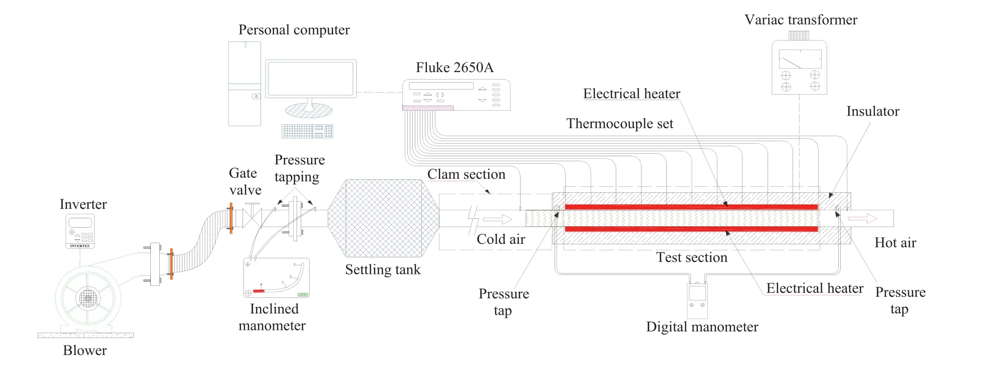
Fig.1.Schematic diagram of experimental apparatus.

Fig.2.Test section with DFT.

Here term A is the convective heat transfer area of the heated duct wall whereas˜Tsis the average surface temperature obtained from local surface temperatures along the axial length of the heated duct.
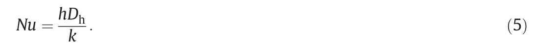
Then,the average Nusselt number is written as
The Reynolds number based on the duct hydraulic diameter(Dh)is given by

where ΔP is the pressure drop across the test section and,U is the mean air velocity of the duct.All thermo-physical properties of air are determined at the overall bulk air temperature from Eq.(3).
The thermal enhancement factor(η)de fined as the ratio of the heat transfer coefficient of an augmented surface,h to that of a smooth surface,h0,at a constant pumping power[26]is given by

4.Flow Structure Simulation of DFT Insert
The system of interest is a uniform heat- fluxed square duct inserted diagonally with the DFT as depicted in Fig.3.The full-length duct is divided into three sections:entry(10H long),test section(14H),and exit(2H).Also the computational domain and grid arrangement used are shown.The physical properties of air have been assumed constant at initial air temperature and no-slip wall conditions were applied to all surfaces.All duct walls are heated with a constant heat- flux(600 W·m-2)while the finned tape is assumed at adiabatic wall conditions.The duct height,H,is 50 mm with the fin-to duct-height ratio,RB=e/H=0.1.Four pitch ratios,RP=P/H=0.5,1.0,1.5 and 2.0,are employed for validation in the current investigation.The numerical model for fluid flow and heat transfer in the duct was developed under the following assumptions:steady,three-dimensional,turbulent and incompressible flow;constant fluid properties;and ignored body forces,viscous dissipation and radiation heat transfer.Based on these assumptions,the duct flow model is governed by the Reynolds averaged Navier-Stokes equations with the realizable k-ε turbulence model and the energy equation.More detail on boundary conditions can be found in Ref.[3].
5.Results and Discussion
5.1.Validation of smooth square duct
The present experimental results of the Nusselt number(Nu)and friction factor(f)obtained from the present smooth duct are compared with the correlations of Dittus-Boelter,Gnielinski,Blasius and Petukhov found in the literature[27]for turbulent flow in ducts:
Correlation of Dittus-Boelter,

Correlation of Gnielinski,


Fig.3.Computational domain and grid.
Correlation of Blasius,
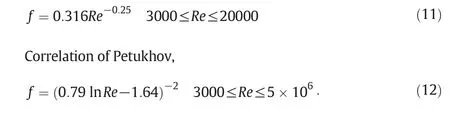
Fig.4 shows a comparison of Nusselt number and friction factor obtained from the present work with those from correlations of Eqs.(9)-(12).In the figure,both the present results reasonably agree well within±5%with the correlations.

Fig.4.Validation of Nu0and f0for smooth duct.Dittus-Boelter correlation;Gnielinski correlation;Nu,Present smooth duct;Blasius correlation;Petukhov correlation;f,Present smooth duct.
5.2.Effect of RBand RPon heat transfer rate
The present experimental result on the heat transfer rate in a uniform heat- fluxed square-duct with DFT inserts presented in the form of Nusselt number ratio,Nu/Nu0against RBand RPat different Re values is displayed in Fig.5a.It is visible in the figure that at a given Re,the Nu/Nu0ratio increases with the increment of RBbut with the decreasing RP.This is because the higher RBand lower RPvalues provide stronger turbulence intensity and vortex strength,that helps to transport the central core flow to the near-wall region.It is noted that for similar operating conditions,the RB=0.2 and RP=0.5 provide the highest Nu/Nu0and are,respectively,about 10%,13%and 27%above the RB=0.15,0.1 and 0.075 and about 9%,14%and 22%over the RP=1.0,1.5 and 2.0.
5.3.Effect of RBand RPon pressure drop
The effect of RBand RPon isothermal pressure drop in terms of friction factor ratio f/f0is depicted in Fig.5b.It is observed that apart from showing a decreasing trend with the fall of Re,the f/f0tends to increase with increasing RBbut shows an opposite trend with RPand is maximized at RB=0.2 and RP=0.5.This is because the DFT gives rise to higher flow blockage and larger surface area.The f/f0values of the RB=0.2 and RP=0.5 are,respectively,about 32%,50%and 66%above that of RB=0.15,0.1 and 0.075;and about 32%,49%and 60%higher than that of RP=1.0,1.5 and 2.0.It is also observed that Nu/Nu0has a slight increase for RB>0.1 while f/f0is increased continuously for the rise of RB.
5.4.Performance evaluation
Nu/Nu0,f/f0and the thermal enhancement factor(η)for the DFT plotted against Re are displayed in Fig.6(a),(b)and(c),respectively.

Fig.5.Variation of(a)Nu/Nu0(b)f/f0with RBand RP.RP=0.5/RB=0.075,Re=4130,Re=13570,Re=23010;RP=1.0/RB=0.10,Re=4130,Re=13570,Re=23010;RP=1.5/RB=0.15,Re=4130,Re=13570,Re=23010;RP=2.0/RB=0.20,Re=4130,Re=13570,Re=23010.
For brevity,only three RBand RPare introduced by neglecting the RB=0.075 and RP=0.5.Nu/Nu0and η tend to decrease with the rise of Re while f/f0shows an opposite trend.In Fig.6(a),it is seen that Nu/Nu0of the DFT is,respectively,around 15%-36%and 32%-49%higher than the wire coil and twisted tape.Over the RBand RPrange investigated,Nu/Nu0is between 2.8-3.6.In Fig.6(b),f/f0of the DFT is maximum at RP=1.0 andRB=0.2 and is about 55%-59%and 80%-82%above that of the wire coil and the twisted tape.The f/f0value of the DFT is found in a range of 5.117.3.
In Fig.6(c),-is decreased as Re increases for all cases.The maximum η is found with RB=0.1 and RP=1.5.Thus,the optimum parameter of the present work is atRB=0.1 because at this point,the highest is obtained no matter whatever RPis.The highest values for the RP=1.5 fined tapes are,respectively,around 1.50 ,1.55,1.69 and 1.60 at RB=0.2,0.15,0.1 and 0.075.Also,the DFT provides the highest,about 26%34%and 21%30%higher than the wire coil and the twisted tape,respectively.Therefore,the newly in vented DFT is expected to be a most promising enhancement device in engineering practice.

Fig.6.Variation of(a)Nu/Nu0,(b)f/f0and(c)η with Refor DFT.RB=0.10,RP=1.0,RP=1.5,RP=2.0;RB=0.15,RP=1.0,RP=1.5,RP=2.0;RB=0.20,RP=1.0,RP=1.5,RP=2.0;Twisted tape,y/W=4;Wire coil,RC=8,Ref.[8].
The Nusselt number and friction factor values for the DFT inserts are correlated as functions of Re,Pr,RBand RP,and they are for mulated as in Eqs.(13)and(14).Correlations for Nusselt number and friction factor of the DFTatRB=0.075,0.1,0.15and0.2;andRP=0.5,1.0,1.5and2.0for Re ranging from 4000 to 25000 are written as
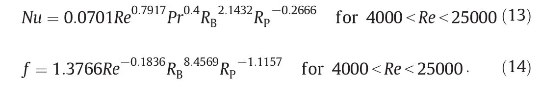
The plots of the Nusselt number and friction factor of the DFT insert,predicted by Eqs.(13)and(14)and measured data are depicted in Fig.7(a)and(b),respectively.In the figure,the majority of the measured data falls within±10%for both of the predicted Nu and f.
5.5.Simulation
The simulated Nu and f of the square duct fitted with the DFTatRB=0.1 are validated by comparison with measurements under similar operating conditions as shown in Fig.8(a)and(b),respectively.The comparison is made for the DFTatRP=0.5,1.0,1.5and2.0.The average discrepancies for both the Nu and f values are less than±10%.
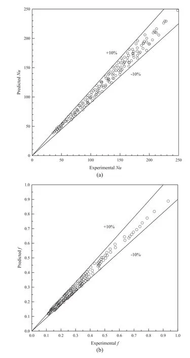
Fig.7.Predicted data of(a)Nu and(b)f versus experimental data for DFT.

Fig.8.Comparison between measurement and simulation of(a)Nu/Nu0and(b)f/f0with Re for using DFT.RB=0.1;RP=0.5,RP=1.0,RP=1.5,RP=2.0 for experimental.RB=0.1;RP=0.5,RP=1.0,RP=1.5,RP=2.0 for simulated.
Fig.9(a)and(b),respectively,displays the streamlines and temperature contours in longitudinal and transverse planes for the DFT with RB=0.1 and RP=1.0 at Re=10000.It is observed clearly in Fig.9(a)that the DFT provides better flow mixing between the central core and the near-wall regions in all directions as can be seen from the longitudinal streamline plot.In Fig.9(b),it is visible that there are two counter-rotating vortices pairs or four longitudinal vortex flows created by DFT along the test duct,leading to higher turbulence intensity.In other words,the DFT enhances the exchange of the cold fluid in the core with that at the near wall regime,which yields a significant effect on the increase of the temperature gradient.
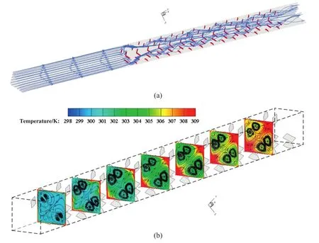
Fig.9.(a)Longitudinal streamlines and(b)Streamlines and temperature contours in transverse planes with DFT at Re=10000,RB=0.1 and RP=1.0.
The local Nusselt number(Nux)contours and streamlines based on Re=10000 for the DFT with RB=0.1,RP=1.0;RB=0.1,RP=2.0 and RB=0.2,RP=1.0 are presented in Fig.10(a),(b)and(c)respectively.In the figure,it is apparent that the higher local Nusselt number values are observed at the impingement/reattachment flow areas on the wall behind the discrete fins.In scrutiny of the DFT with RB=0.2,it is visible that the higher local Nusselt number values appear to be in a larger region than those of the one with lower RB.This is because the DFT with RB=0.2 can induce larger recirculation or stronger vortex flow appearing behind the fins than the one with lower RB.It is seen that the DFT with RP=1.0(Fig.10(a))displays the reattachment of flow or the helical flow pitch shorter than the DFT with RP=2.0(Fig.10(b)),effecting to the increase of heat transfer rate.
6.Conclusions
An experimental and numerical work has been done to investigate air flow friction and heat transfer characteristics in a square duct inserted diagonally with a DFT at different RBand RPfor the turbulent flow,Re from 4000 to 25000.The DFT parameters mentioned above have a significant effect to the change of flow in duct leading to the increment of both the heat transfer rate and pressure drop.It is observed that the maximum of heat transfer and pressure drop from the DFT insert is found at the highest RBbut at the lowest RP.For thermal performance comparison,the DFT at RP=1.5 and RB=0.1 yields the highest thermal enhancement factor of about 1.69 at the lowest Re.In numerical study,the DFT gives rise to two longitudinal counterrotating vortices along the duct that help increase turbulence intensity.The mechanism of heat transfer enhancement is the impingement/reattachment flow of the longitudinal vortex flows.
Nomenclature
A convection heat transfer area of duct,m2
Cpspecific heat capacity of air,J·kg-1·K-1
Dhhydraulic diameter of square duct(=H),m
w wire thickness,m
e fin height,m
f friction factor
H duct height,m
h average heat transfer coefficient,W·m-2·K-1
k thermal conductivity of air,W·m-1·K-1
L length of test duct,m
m mass flow rate of air,kg·s-1
Nu Nusselt number(=hD/k)
P fin pitch spacing,m
Δp pressure drop,Pa
Pr Prandtl number(=Cpμ/k)
Q heat transfer,W
RBfin blockage ratio(=e/H)
RCcoil pitch ratio(=S/w)
Re Reynolds number(=UD/ν)
RPfin pitch ratio(=P/H)
S spring pitch spacing,m
T temperature,K
t thickness of fin,m
U mean velocity,m·s-1
W tape width,m
y pitch length of twisted tape(180°rotation),m
α attack angle of fin,(°)
η thermal enhancement factor(=(Nu/Nu0)/(f/f0)1/3)
μ viscosity of air,kg·ms-1
ν kinematics viscosity,m2·s-1
ρ density of air,kg·m-3
Subscripts
b bulk
conv convection

Fig.10.Nuxcontour and streamlines at Re=10000 for DFT with(a)RB=0.1,RP=1.0;(b)RB=0.1,RP=2.0;and(c)RB=0.2,RP=1.0.
i inlet
o outlet
pp pumping power
s duct surface
0 smooth duct
 Chinese Journal of Chemical Engineering2015年3期
- Chinese Journal of Chemical Engineering的其它文章
- Micromixing characteristics in a gas-liquid-solid stirred tank with settling particles☆
- An experimental study of drag reduction by nanofluids in slug two-phase flow of air and water through horizontal pipes☆
- Effect of surfactant type on interfacial area and liquid mass transfer for CO2absorption in a bubble column☆
- Effects of bubbly flow on bending moment acting on the shaft of a gas sparged vessel stirred by a Rushton turbine☆
- A novel purification process for dodecanedioic acid by molecular distillation
- Purification and separation of durene by static melt crystallization☆