
Decoupling Trajectory Tracking for Gliding Reentry Vehicles
2015-08-11 11:57ZixuanLiangZhangRenandXingyueShao
Zixuan Liang,Zhang Ren,and Xingyue Shao
Decoupling Trajectory Tracking for Gliding Reentry Vehicles
Zixuan Liang,Zhang Ren,and Xingyue Shao
—A decoupling trajectory tracking method for gliding reentry vehicles is presented to improve the reliability of the guidance system.Function relations between state variables and control variables are analyzed.To reduce the coupling between control channels,the multiple-input multiple-output(MIMO) tracking system is separated into a series of two single-input single-output(SISO)subsystems.Tracking laws for both velocity and altitude are designed based on the sliding mode control (SMC).The decoupling approach is verified by the Monte Carlo simulations,and compared with the linear quadratic regulator (LQR)approach in some specific conditions.Simulation results indicate that the decoupling approach owns a fast convergence speed and a strong anti-interference ability in the trajectory tracking.
Index Terms—Hypersonic,reentry vehicle,decoupling control, trajectory tracking,sliding mode control(SMC).
I.INTRODUCTION
H YPERSONIC vehicles are aircrafts with a speed of Mach 5 or higher.The two typical hypersonic vehicles are the air-breathing cruise vehicle[1−2]and the un-powered gliding reentry vehicle[3].The latter can remotely maneuver in the near space(from about100 km to 20 km in altitude[4])without any power.Since the flight environment of the near space is terrible,an advanced guidance,navigation and control(GNC) system has become one of the key technologies for the reentry flight[5].
The reentry guidance method based on a reference trajectory is a common approach that has been successfully used in the Shuttle[6−7].The basic idea of this approach is tracking a predesigned reference trajectory onboard during the reentry flight. However,the tracking law design is usually complex mainly due to the following reasons:
1)Strong nonlinear terms exist in the reentry dynamic model;
2)Parameters in the aerodynamic model are with high uncertainty;
3)The number of state variables(altitude,range-to-go, velocity,heading angle,etc.)is greater than that of control variables(only the angle of attack and the bank angle).
To solve this tracking problem,[8]proposed an approximate receding-horizon control law based on the linearized timevarying model with six state variables.Under this control law,the three-dimensional trajectory can be tracked well when the flight initial condition is dispersed.But for large aerodynamic dispersions,it is sometimes hard for this law to own a good performance.In[9],the longitudinal trajectory consisting of three state variables was analyzed and a tracking law based on the linear quadratic regulator(LQR)was developed. Though the guidance algorithm in this approach is much more simplified,its anti-interference ability is not always perfect as the feedback matrix is designed off-line.To improve the performance of trajectory tracking,[10]investigated an adaptive control method,[11]used a prediction control approach,[12] introduced the predictive controllerinto the drag tracking,[13] studied a tracking law based on the inversion control,[14] proposed an adaptive optimal sliding mode controller,and [15]presented a flatness approach.However,most of these approaches are designed based on the multiple-inputmultipleoutput(MIMO)system where couplings exist among control channels,and significantly complex algorithm is required to overcome the couplings.
In fact,to ensure the reliability of the control and guidance system,the trajectory tracking law should be designed under the following two principles:
1)The tracking law is robust to any dispersion;
2)The algorithm is simple to be employed.
In this paper,a decoupling approach is proposed for the design of the trajectory tracking law.Different from those complex approaches mainly focusing on the first principle, this study pays attention to both principles.
In the longitudinalplane,to simplify the tracking algorithm, the MIMO system for the multi-objective tracking is separated into a series of two single-input single-output(SISO)subsystems.The former is for velocity tracking,and the latter is for altitude tracking.In each subsystem,to overcome the model uncertainty,sliding mode control(SMC)is used in the tracking law.Finally,simulations on a gliding reentry vehicle modelare carried out to validate the proposed approach.
II.REENTRY GUIDANCE PROBLEM
A.Reentry Dynamics
The three-degree-of-freedom(3 DOF)point-mass equations of an un-powered reentry vehicle over a spherical rotating Earth are as follows[16−17]:


Here,r is the radial distance from the center of the Earth to the vehicle.θandφare longitude and latitude,respectively. v is the Earth-relative velocity.γandψare the flight path angle and the velocity heading angle,respectively.σis the bank angle.g is the gravitational acceleration,andωis the angular rate of Earth rotation.L and D are the aerodynamic lift and drag accelerations,i.e.,
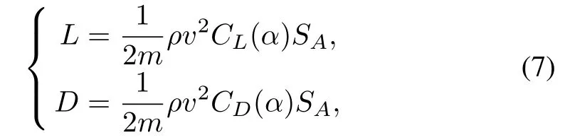
where m is the mass of the vehicle,SAis the reference area, CLand CDare the liftand drag coefficients thatdepend on the angle of attackα,andρis the atmospheric density calculated by
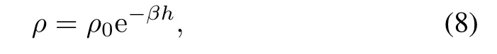
whereρ0is the atmospheric density on the surface ofthe Earth, andβis a constant.h is the altitude and has the relationship with r as in(9),where R0is the radius of the Earth.

B.Guidance Strategy
The guidance system's mission is to provide commands with which the vehicle can travel from the initial interface to the terminal interface and the flight constraints are well satisfi ed. To simplify this system,we can design it separately in the longitudinal and lateral planes.
In the lateral plane,the control variable is the sign of the bank angle.With a conventional heading error corridor,the bank reversal logic is designed as
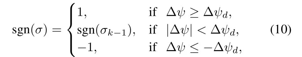
whereσk−1is the bank angle command in the previous guidance cycle,Δψ is the heading error andΔψdis the boundary of the heading error corridor.
In the longitudinal plane,the control variables include the magnitude of the bank angle and the angle of attack.The task for longitudinal guidance is tracking the reference trajectory with the flight constraints satisfied.The three typical reentry constraints are expressed as follows[17−18]:
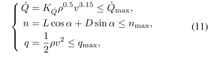
where˙Q is the heating rate,n the normal aerodynamic load, q the dynamic pressure,and K˙Qis a constant.
Generally,a reference longitudinal trajectory is planned by the off-line optimization to satisfy reentry constraints,and then a reliable tracking law is employed onboard to track this reference trajectory.
III.DECOUPLING TRAJECTORY TRACKING
A.Decoupling Design for Guidance System
The main state variables in the longitudinal plane are altitude,velocity,flight path angle and range-to-go stogo.As the flightpath angle can be controlled by the stable tracking of altitude,the task for control can be simplified to tracking the altitude and velocity trajectories with stogoas the independent variable.
Considering thatω2≈ 0 andγ≈ 0 in(4),the derivative of velocity is controlled directly by the aerodynamic drag D. Similarly,from(1)and(5),the derivative of altitude(which equals to the rate of r)is found to be controlled by L cosσ. Furthermore,L and D in(7)mainly depend onρ,v andα. Therefore,the function relations among controlvariables(the bank angle and the angle of attack)and state variables(altitude and velocity)are obtained as in Fig.1.

Fig.1. Function relations for control variables.
From Fig.1,itis found thatthe angle of attack has a direct effect on velocity,but the bank angle affects the velocity indirectly through flight path angle,altitude and the atmospheric density.After neglecting effects of the bank angle on velocity, the simplified relations are given by Fig.2.The velocity and the altitude are controlled by the angle of attack and bank angle,respectively,since the function from the angle of attack to the altitude can be supposed as dispersion in the lift model.
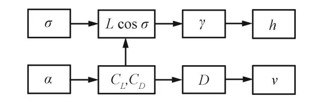
Fig.2. Simplified function relations for control variables.
Hence,the MIMO system for longitudinaltrajectory control can be separated into two SISO subsystems:the velocity control and the altitude control.Considering that the angle of attack has an effect on altitude,a series connection for the two controllers is employed.The control diagram is designed as in Fig.3.

Fig.3.Diagram for decoupling tracking approach.
In Fig.3,the reference trajectory is given by the off-line optimization and saved as several discrete sequences, i.e., [v0,v1,v2,···,vn], [h0,h1,h2,···,hn], and [s togo,0,s togo,1,s togo,2,···,s togo,n]. Given s togo ∈
[stogo,i+1,stogo,i],the reference velocity and altitude are calculated by(12)and(13).The first or second derivatives for vrefand hrefused in the trajectory tracking law can be calculated by the numericaldifferentiation,since the optimized reference trajectory is usually smooth.

B.Velocity Tracking Law
The task for the velocity tracking is to track the reference velocity trajectory vrefwith the angle of attack as the control variable.First,neglecting the second order term ofω,the differential equation for the velocity in(4)can be expressed as
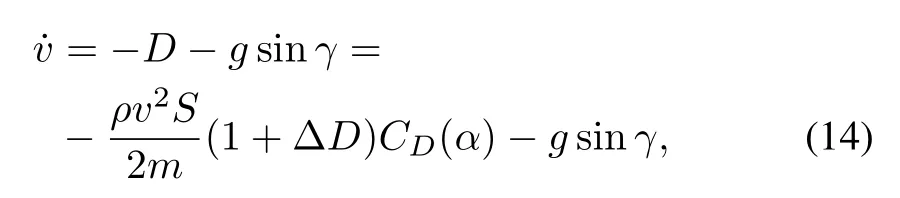
whereΔD is the uncertainty in the drag model including errors ofthe atmospheric density,the liftand drag coefficients, and the vehicle mass.With the state variable x=v and the control variable u=CD(α),a first order SISO system for the velocity is obtained,which is

Though an uncertain term exists in Bv,it is supposed to be bounded by
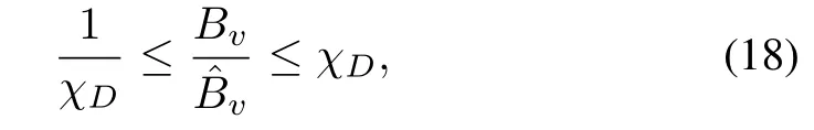
whereˆBvis the estimation of Bvand computed by setting ΔD to be zero in(16).
To overcome the uncertainty,the SMC theory is to be used in the tracking law design.Define the sliding surface

Combining with(15),we have

Hence,the control law based on SMC is given by

Substituting(21)into(20),we have

where kvis designed as

By substituting(23)into(22),it can be proved that the sliding condition is satisfied as
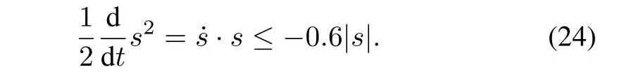
To reduce the chattering,the saturation function is employed and the control law is replaced by(25),whereΩvis the boundary layer thickness for the velocity tracking,and is set in a time varying formΩv=0.01v.

At last,the guidance command for the angle of attack can be computed from CD(α)=u.
C.Altitude Tracking Law
The task for the altitude tracking is to track the reference altitude trajectory hrefwith the bank angle as the control variable.From(1),the differential equation for the altitude is

By a further derivation and combining with(4)and(5),the second order differential of altitude is expressed as

whereΔL andΔD are the uncertainties in the lift and drag models,respectively.
Equation(27)establishes the relation between bank angle and altitude.With the state variable x=h and the control variable u=cosσ,a second order SISO system forthe altitude is obtained,i.e.,
where Bhand Fhare supposed to be bounded by

whereˆBhandˆFhare estimations of Bhand Fh,and can be calculated by settingΔL andΔD to be zero in(28)and(29), respectively.
Then,define the sliding surface

Combining with(30),we have
Similar to the velocity tracking law,the SMC theory and the saturation function are employed,and the tracking law for the altitude is given by

whereΩhis the boundary layer thickness for the altitude tracking and set in a time varying formΩh=0.012v,and khis designed as

Finally,the guidance command for bank angle is given by σ=arccos u.
IV.SIMULATIONS AND ANALYSIS
A model for the gliding reentry vehicle is used in simulations to test the decoupling trajectory tracking method presented in this study.The reentry initial conditions are as fell h0=75 km,v0=7 200 m/s,θ0=10 deg,φ0=0 deg,γ0=−0.5 deg,ψ0=49 deg,stogo,0=11 127 km.The terminal conditions are:hf=40 km,vf=2 950 m/s,|Δψf|≤5 deg, and stogo,f=150 km.The flight constraints are:Qmax= 3 MW/m2,nmax=3 g,qmax=100 kPa.Other parameters in the trajectory tracking laws are configured asχL=χD=1.6, δh=0.5.
A.Simulations for Robustness
Simulations of reentry flight in dispersed cases are performed to testthe robustness ofthe trajectory tracking method. Typical dispersions for reentry initial conditions and aerodynamic parameters are configured in Table I.With these dispersions,the Monte Carlo simulations are employed for a totalof 1 000 cases ofreentry flight.The altitude and velocity histories with stogoas the independent variable are shown in Figs.4 and 5,respectively.It is seen that the decoupling method is effective on both tracking speed and tracking accuracy forboth altitude and velocity trajectories.

Fig.4.Altitude histories for 1 000 dispersed cases.
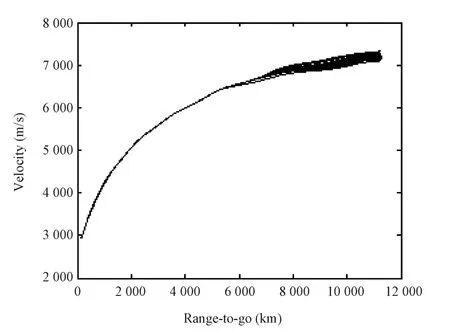
Fig.5. Velocity histories for 1 000 dispersed cases.
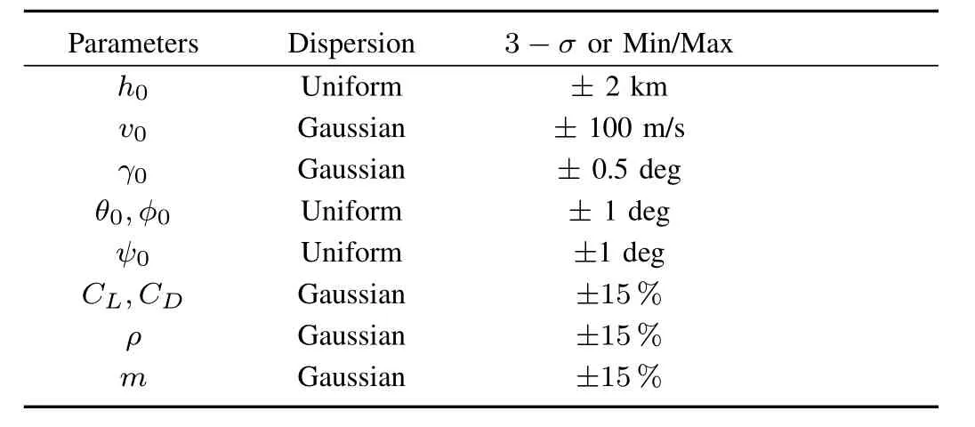
TABLE I DISPERSIONS IN MONTE CARLO SIMULATIONS
Fig.6 expresses the distribution for the terminal velocityaltitude errors in the 1 000 dispersed cases.The altitude errors are kept in 0.3 km,and the velocity errors are kept in 10 m/s. The ground tracks for the 1 000 dispersed cases are shown in Fig.7,which indicates that the lateral guidance performs well.The distribution for the terminal heading errors is shown in Fig.8.It is seen that the heading errors are kept within ±5 deg,which indicates that the terminal constraint is well satisfied.

Fig.6. Terminal h−v errors for 1 000 dispersed cases.
B.Comparison of Different Methods
The trajectory tracking law based on LQR is another simply designed method and has been used in many studies[9,19−21]. Simulations in the same specific conditions are performed tocompare the decoupling guidance method based on SMC with the conventional guidance method based on LQR.

Fig.7. Ground tracks for 1 000 dispersed cases.

Fig.8.Terminal heading errors for 1 000 dispersed cases.
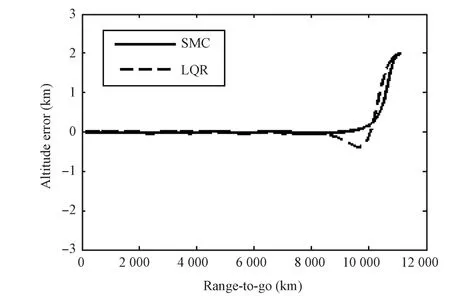
Fig.9.Comparison of the altitude errors for two methods.
First,the two methods are simulated with dispersions forthe flightinitialconditionΔh0=2 km andΔv0=50 m/s.Figs.9 and 10 record the altitude error histories for the two methods. Although both methods can reduce the altitude error and the velocity errorto zero atthe reentry terminal,the SMC method has an advantage in the convergence speed.
Secondly,the two methods are simulated in four conditions with different dispersions for the lift and drag coefficients. Simulation results are shown in Tables II and III.For the decoupling SMC method,the terminal altitude errors are within 0.2 km and the terminal velocity errors are in within 5 m/s.However,for the conventional LQR method,the terminal errors in the first three conditions are acceptable,but divergence appears in the last condition.Hence,compared with the conventional LQR method,the proposed decoupling approach based on SMC has the better anti-interference ability for the aerodynamic dispersions.
In summary,the new decoupling SMC approach is more effective than the conventional LQR approach.
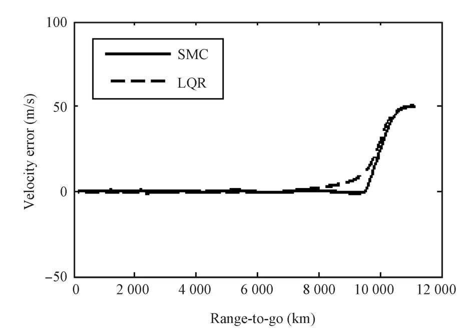
Fig.10.Comparison of the velocity errors for two methods.
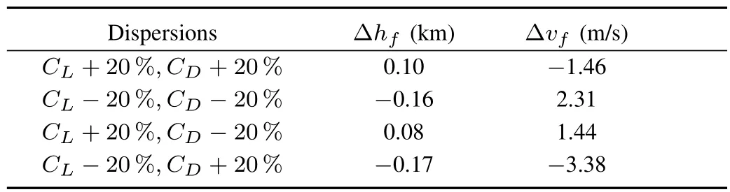
TABLE II SIMULATION RESULTS FOR THE DECOUPLING SMC METHOD
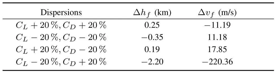
TABLE III SIMULATION RESULTS FOR THE CONVENTIONAL LQR METHOD
V.CONCLUSION
In this paper,the traditional multi-objective tracking problem for the reentry trajectory is separated into the altitude tracking and the velocity tracking,and both of the tracking laws are designed with the SMC theory.From Monte Carlo simulations of 1 000 dispersed cases,the decoupling tracking method is shown to be robust to the uncertain reentry conditions.From the comparison with the conventional LQR method,itis indicated that the decoupling tracking law owns better performance in the convergence speed and the antiinterference ability for large dispersions.
With the decoupling strategy presented in this paper,the trajectory tracking algorithm for the reentry vehicle is significantly simplified.In future works,other control theories for a SISO system can be applied to the altitude tracking law and the velocity tracking law based on this decoupling strategy.
REFERENCES
[1]Xu B,Sun F,Liu H,Ren J.Adaptive Kriging controller design for hypersonic flight vehicle via back-stepping.IET Control Theory and Applications,2012,6(4):487−497
[2]Yang J,Li S H,Sun C Y,Guo L.Nonlinear-disturbance-observer-based robust flight control for airbreathing hypersonic vehicles.IEEE Transactions onAerospace and Electronic Systems,2013,49(2):1263−1275
[3]Stewart J D,Greenshields D H.Entry vehicles for space programs. Journal of Spacecraft and Rockets,1969,6(10):1089−1102
[4]Sun Chang-Yin,Mu Chao-Xu,Yu Yao.Some control problems for near space hypersonic vehicles.Acta Automatica Sinica,2013,39(11): 1901−1913(in Chinese)
[5]Bao Wei-Min.Presentsituation and developmenttendency of aerospace control techniques.Acta Automatica Sinica,2013,39(6):697−702(in Chinese)
[6]Harpold J C,Graves C A.Shuttle entry guidance.Journal of the Astronautical Sciences,1979,27(3):239−268
[7]Lu P.Entry guidance and trajectory controlfor reusable launch vehicle. Journal of Guidance,Control,and Dynamics,1997,20(1):143−149
[8]Lu P.Regulation about time-varying trajectories:precision entry guidance illustrated.Journal of Guidance,Control,and Dynamics,1999, 22(6):784−790
[9]Dukeman G A.Profile-following entry guidance using linear quadratic regulator theory.In:Proceedings of the 2002 AIAA Guidance,Navigation,and Control Conference and Exhibit.Monterey,USA:AIAA, 2002.2002-4457
[10]Mooij E.Model reference adaptive guidance for re-entry trajectory tracking.In:Proceedings of the 2004 AIAA Guidance,Navigation,and Control Conference and Exhibit.Providence,USA:AIAA,2004.2004-4900
[11]Zhang Jun,Xiao Yu-Zhi,Bi Zhen-Fa.Guidance method based on multimodel prediction for re-entry vehicles.Acta Aeronautica et Astronautic Sinica,2008,29(Sup):S20−S25(in Chinese)
[12]Benito J,Mease K D.Nonlinearpredictive controllerfordrag tracking in entry guidance.In:Proceedings of the 2008 AIAA/AAS Astrodynamics Specialist Conference and Exhibit.Honolulu,USA:AIAA,2008.2008-7350
[13]Pu Z Q,Tan X M,Fan G L,Yi J Q.Design of entry trajectory tracking law for a hypersonic vehicle via inversion control.In:Proceedings ofthe 10th World Congress on Intelligent Control and Automation.Beijing, China:IEEE,2012.1092−1097
[14]Zhu Kai.Study of Reentry Guidance and Control Algorithm for Glide Missile[Ph.D.dissertation],Harbin Institute of Technology,China, 2011.(in Chinese)
[15]Desiderio D,Lovera M.Guidance and control for planetary landing: flatness-based approach.IEEE Transactions on Control Systems Technology,2013,21(4):1280−1294
[16]Vinh N X,Busemann A,Culp R D.Hypersonic and Planetary Entry Flight Mechanics.Ann Arbor,MI:University of Michigan Press,1980. 26−28
[17]Xue S B,Lu P.Constrained predictor-corrector entry guidance.Journal of Guidance,Control,and Dynamics,2010,33(4):1273−1281
[18]Li H F,Zhang R,Li Z Y,Zhang R.New method to enforce inequality constraints of entry trajectory.Journalof Guidance,Control,and Dynamics,2012,35(5):1662−1667
[19]Li Yu.Study of Trajectory Optimization and Guidance Algorithm for Boost-Glide Missile[Ph.D.dissertation],Harbin Institute of Technology, China,2009(in Chinese)
[20]Liang Z X,Ren Z,Bai C.Lateral reentry guidance for maneuver glide vehicles with geographic constraints.In:Proceedings of the 32nd Chinese Control Conference.Xi'an,China:IEEE,2013.5187−5192
[21]Zhou W,Tan S,Chen H.A simple reentry trajectory generation and tracking scheme for common aero vehicle.In:Proceedings of the 2012 AIAA Guidance,Navigation,and Control Conference.Minneapolis, USA:AIAA,2012.2012-4709
Zixuan Liang Ph.D.candidate at the Science and Technology on Aircraft Control Laboratory,Beihang University.His research interests include guidance and control technology for the reentry vehicles.Corresponding author of this paper.
Zhang Ren Professoratthe Science and Technology on Aircraft Control Laboratory,Beihang University.His research interests include precision guidance, optimal control,adaptive control,computer control and simulation.
Xingyue Shao Ph.D.candidate at the Science and Technology on Aircraft Control Laboratory,Beihang University.His research interests include guidance and control technology for the reentry vehicles.
t
September 9,2013;accepted May 28,2014.This work was supported by National Natural Science Foundation of China(91116002, 91216034,61333011,61121003).Recommended by Associate Editor Bin Xian
:Zixuan Liang,Zhang Ren,Xingyue Shao.Decoupling trajectory tracking for gliding reentry vehicles.IEEE/CAAJournalofAutomaticaSinica, 2015,2(1):115−120
Zixuan Liang,Zhang Ren,and Xingyue Shao are with the Science and Technology on Aircraft Control Laboratory,Beihang University,Beijing 100191,China(e-mail:aliang@buaa.edu.cn;renzhang@buaa.edu.cn; shao86830@163.com).
 IEEE/CAA Journal of Automatica Sinica2015年1期
- IEEE/CAA Journal of Automatica Sinica的其它文章
- Guest Editorial for Special Issue on Autonomous Control of Unmanned Aerial Vehicles
- Continuous Sliding Mode Controller with Disturbance Observer for Hypersonic Vehicles
- Adaptive Backstepping Tracking Control of a 6-DOF Unmanned Helicopter
- A Predator-prey Particle Swarm Optimization Approach to Multiple UCAV Air Combat Modeled by Dynamic Game Theory
- Finite-time Attitude Control:A Finite-time Passivity Approach
- Autonomous Landing of Small Unmanned Aerial Rotorcraft Based on Monocular Vision in GPS-denied Area