
Autonomous Landing of Small Unmanned Aerial Rotorcraft Based on Monocular Vision in GPS-denied Area
2015-08-11 11:57CunxiaoMiaoandJingjingLi
Cunxiao Miao and Jingjing Li
Autonomous Landing of Small Unmanned Aerial Rotorcraft Based on Monocular Vision in GPS-denied Area
Cunxiao Miao and Jingjing Li
—Focusing on the low-precision attitude of a current smallunmanned aerialrotorcraftat the landing stage,the present paper proposes a new attitude controlmethod for the GPS-denied scenario based on the monocular vision.Primarily,a robust landmark detection technique is developed which leverages the well-documented merits of supporting vector machines(SVMs) to enable landmark detection.Then an algorithm of nonlinear optimization based on Newton iteration method for the attitude and position of camera is put forward to reduce the projection error and get an optimized solution.By introducing the wavelet analysis into the adaptive Kalman filter,the high frequency noise of vision is filtered out successfully.At last,automatic landing tests are performed to verify the method's feasibility and effectiveness.
Index Terms—Automatic landing,monocular vision,attitude, wavelet filter.
I.INTRODUCTION
W ITH the ability to take off and land vertically,along with hovering ability,the smallunmanned aerialrotorcraft(SUAR)has an irreplaceable role in civilapplications[1]. Thus,it has been widely used in many regions,such as road traffic monitoring,data acquisition,mapping and surveillance, etc[2−4].And it allows us to easily access environments to which no humans or other vehicles can get access.
Now most navigation systems for SUAR are based on inertial sensors(gyroscopes and accelerometer)and GPS[5−6]. However,buildings and other obstacles in urban environments can easily disturb the GPS signal and even cause the signal to get lost due to electromagnetic noise from active emitters and multi-path effects.And it directly leads to the poor performance of SUAR as a result of the inertial navigation errors generated by the gyroscope drifts and accelerometer biases without GPS.So there is a requirementthatthe vehicle is able to navigate without using GPS to guarantee the safety of operations in unknown,unstructured and GPS-denied environments.
Considering the problem mentioned above,a feasible solution is to navigate the vehicle using a system based on vision.Small cameras which are low-lost,light-weight and passive are attractive sensors for SUAR.Furthermore,a vision system is self-suffi cient,and provides position values which are much more accurate than the standard GPS's(cm accuracy).Off-board cameras for motion capture systems are well studied[7−8].However,the cameras can be used only in small environments that are accessible physically by humans,and the cameras's field of view directly constrains the operation of the helicopter.Therefore,it is necessary to install the camera onboard.Saripalli used vision for the precise target detection and recognition and the navigation successfully in combination with GPS[9].Moreover,Hermansson established an EKF model to fuse the measurements of vision,GPS and compass,and realized a landing within 0.5 m in the horizontal direction[10].Obviously,these systems still relies on the GPS signal.The stereo vision is also used to detectthe safe landing area and to achieve soft landing[11−12].However,the range data become inaccurate when the distance to the scene is much larger than the baseline[13].
In this paper,we propose an autonomous landing method for SUAR to tackle the problem of poor navigation in GPS-denied environment by using a single camera and onboard inertial sensors.The position and attitude of the SUAR are estimated by the vision system using a specially designed landmark firstly.Then a wavelet-adaptive KF is developed by fusing the position estimated by the vision system with inertial data to improve the performance of SUAR.
The paper is organized as follows:The image processing algorithm is described in Section II.In Section III,an adaptive-KF based on wavelet filter is proposed to get high-precision estimated values.Simulation and test results confirm the effectiveness of the proposed method in Section IV.Finally, conclusions are drawn in Section V.
II.THE DESCRIPTION OF VISION SYSTEM
To land successfully,two basic stages are required by the visual navigation system for SUAR:the landmark detection and the accurate estimation of position and attitude for SUAR.
A.Landmark Detection Based on SVM
As a basic step of a visualnavigation system,usually there are three methods for landmark detection.Special landmarksare identified easily,but this approach cannot be applied commonly.Besides,pattern matching[14]is a mostly used way, too.However,the main shortcomings are the large calculation and vast experiments are needed when dividing the similarity threshold.Machine learning[15−16]is recognized as the most intelligent method,and can be used commonly to detect any landmark.
In order to significantly improve the effect of landmark detection,an innovative landmark detection technique was studied and finally specified.Its support vector machine (SVM)takes advantage of the Hu invariant moments[17].
A series of Hu invariant moments of several images of landmark are used as inputto the SVM,which now is widely used for detection purposes and is based on a training set of elements.Basically,the SVM technique aims to geometrically separate the training set represented in a n space,with n standing for the number of criteria taken into account for classification,using a hyper-plane or some more complex surface if necessary.The SVM training algorithm finds out the best frontier in order to maximize the margin,defined as a symmetric zone centered on the frontierwith no training points included,and to minimize the number of wrong classification occurrences,as which can be shown in Fig.1.
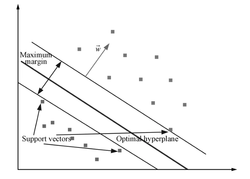
Fig.1.SVM detection in the two-dimensional space.
The output of SVM training stage is thus the hyper-plane equation[18]
where→x is the n components vector representing the image to be classified.It should be noted that the normal vector→w is a linear combination of a reduced setof training vectors→x, located nearby the two parallelhyper-planes defining the margin:points located far from the margin have no contribution in the hyper-plane definition.
Then the classification algorithm is straight forward:if→yi(〈→w,→xi〉+b)−1≥ 0,then the corresponding mark is classified as landmark-free.
When the linear separation is not efficient,it often proves to become linear when applying some non-linear transform on the coordinate,and SVM technique would be applied to achieve efficiently this non-linear transform using kernels.
In addition,the SVM convex programming problem can be converted to a dual problem using Lagrange method. That is,a conditional extremum can be constructed as min‖w‖2/2,s.t. →yi(〈→w,→xi〉+b)−1≥0.Here,we use thedefined as minw,bmaxαi≥0L(w,b,αi).Then,the expression above can be transformed through dualistic transformation as maxαi≥0minw,bL(w,b,αi).Then the problem can be resolved using a series of numerical method[19].
As the input to SVM,the first,second and third moments of inertia are testified to be sufficient to distinguish between the landing target and other objects presented in the image. The moments of inertia can be shown as

whereφ1,φ2,φ3are the three lower order invariantmoments, andηpqis the normalized central moment which can be defined as
whereγ=p+2q+1,p+q=2,3,···andµpqrepresents the central moment of an object,which is given by
where(¯x,¯y)represents the center of the gravity of the object, f(x,y)represents a two-dimensional object as a continuous function with p,q=0,1,2,···.
B.State Estimation Based on Vision
We have chosen black triangles on white background as they are fast to detect and provide accurate image features. When the landmark is detected in the current image,corners are extracted by the Kitchen and Rosenfild algorithm.Then from the projection ofthe cornerpoints ofthe targetlandmark, the attitude and position of the SUAR is uniquely determined through the following equations,if allintrinsic camera parameters are known.

Suppose that the landmark is detected,and the normalized coordinates of the corner in the navigation system can be represented as qqqi(i=1,2,···,12)(12 points are used in this research),and the corresponding coordinates in the image plane is xxxi=[u v 1]T(i=1,2,···,12);then the simplified form of(5)can be expressed as follows

whereλiis equal to zc,and thus we can obtain thatλi=where eeeT3=0 0 1.
If yyyi=AAA−1xxxi,then we can define Formula(6)as


and rrr3=rrr1×rrr2.Finally,the attitude of the SUAR can be obtained from RRR.
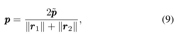
Through the linear algorithm above, 9 variables (rrr1,rrr2,ppp)composed of attitude and position parameters ϕ,θ,ψ,p1,p2,p3can be estimated.It is clear that the 9 variables contain much noise,but they can be used as initial values of the non-linear algorithm below.
The estimation from the non-linear algorithm is optimized by minimizing the reprojection error G as below
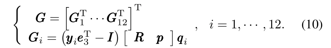

Therefore,the attitude and position parameters based on Newton method can be expressed as

III.SENSOR FUSION
The attitude and position information from the vision system cannot be fed back to the controller directly because of their lack of robustness.
Therefore,a filter based on Kalman filter(KF)is developed to fuse highly accurate position estimated from vision system with inertial data from the inertial measurement unit(IMU, including angular rate gyroscope and accelerometers).Not only can the filter filter out most of the noise,but it can also provide sufficient information to complete the task when the vision system is disturbed.
A.The State and Observation Model of SUAR
The KF is done using the error state space as follows
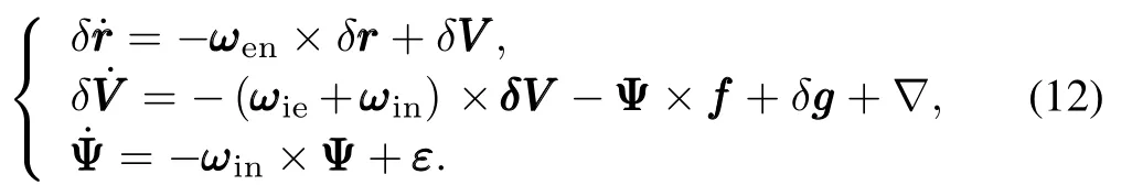
We can conclude the discrete state equation XXXk= Φk,k−1XXXk−1+WWWk−1.In(12),δrrr,δVVV andΨare the error vectors of the position,velocity and attitude,ωieis the Earth rotation rate,fff is the accelerometers outputs,▽is the bias of accelerometer,εis the zero driftof gyroscope,XXXkis the state vector,Φk,k−1is the state transition matrix and WWWkrepresents the system noise.
The three observations are obtained by the difference between the position from vision system and the position from INS.Then the observational equation can be given as

where ZZZkis the observation vector and VVVkis the observation noise.
B.The Wavelet-adaptive KF
1)The wavelet filter method
Sensor noises are always treated as zero mean Gaussian white noise in traditional Kalman filter.However,to get high precision position and attitude information,it's necessary to get rid of high frequency noises in the sensors(SINS and vision system).The common ways to deal with the high frequency noises include the data smoothing filter,infinite impulse response(IIR)filter,finite impulse response(FIR) filter and wavelet filter.The data smoothing can eliminate the measurement outlier and noise for the high frequency data, but it has high requirement for the sensor data collection system.Although the IIR can eliminate the high frequency noise,itcan cause a phase delay.The FIR can reduce the noise signal energy,but it has limitation in the high frequency noise suppression.Wavelet filter is a time domain and frequency domain method,having good representation for the partial signal characteristic.In the low frequency region,it has a higher frequency resolution and lower time resolution.On the other hand,ithas higher time resolution and a lower frequency resolution in the high frequency region.Therefore,wavelet filter is used as a tool to reduce high frequency noises in the sensor information.
We can suppose the data with noise as

where f(t)and g(t)represent the real signal and noise respectively.Besides,they are independent of each other,and ε(t)∈N¡0,σ2¢.
The process of wavelet decomposition and reconstruction scheme includes three steps:
a)Wavelet decomposition
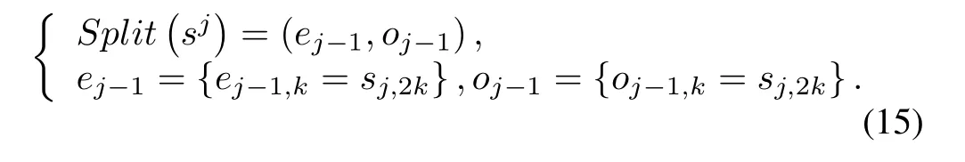
b)Prediction:defining the detailed representation characteristics by choosing a predictor.

c)Update:averaging the signal of rough representation against the original signal.

2)AKF description
The Kalman filter is a setof mathematicalequations thatuse an underlying process model to estimate the current system state and correct the estimated value.Using this predictorcorrectormechanism,itcan approximate an optimalestimation from the linearization ofthe process and measurementmodels.
Then the filter consists of the following stages:
a)State prediction

b)Measurement prediction

c)Updated state estimation

d)Gain of the filter

e)Error covariance

f)Variance matrix of the observation noise
Considering that the noise structure has changed after wavelet filtering,we cannot simply use experiential value or the statistics of partialnoise as the observation noise variance; here the observation noise variance is estimated using the maximum by a posteriori adaptive method.

IV.SIMULATION AND EXPERIMENT
A.System Description
To test the effectiveness of the proposed method,an autopilot with embedded system based on 2 pieces of highspeed DSPs and microcontroller were developed,to realize the complex algorithms of image processing,navigation and control,as shown in Fig.2.In addition,it consists of a horizontal main board,housing 3-axis rate gyroscopes,3-axis accelerometers and a barometer.The gyro employs the LCG50 produced by System Donner Inertial Company in British.The accelerometer is the Model 1221 manufactured by Silicon Designs Company in Japan.Besides,the camera used here is a RICOR aerial camera,which is light(about 188 g),with a fixed focal length about 6 mm.In view of the time limit, we set the frame frequency at 5 f/s.For flight stability,the navigation and control cycle are set at 50 Hz.Besides,the data fusion method is conducted in 1 Hz of data frequency and the coefficient w is determined by a series of images of the landmark before landing.
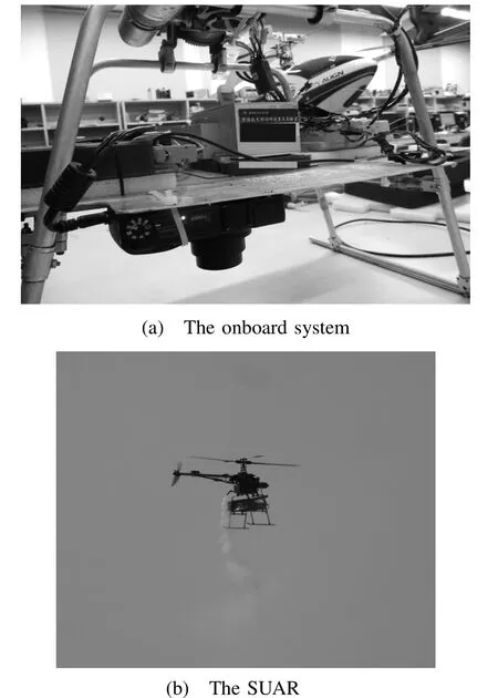
Fig.2.The onboard system and the SUAR used in the experiment.
B.Autonomous Landing Test
The landing pad used here is a 1.2 m×1.2 m specially made landmark.The flight trajectory of the SUAR in the landing process is shown in Fig.3.When the SUAR arrives above the landing area,it starts to search for the landmark and begin to land.With the constant adjustment for the planed hovering altitude,the SUAR descends the altitude with hovering station. When the altitude is less than 2 m,the system reaches to the land disturbance region.Since there exists land disturbance,the pilot control model[20]is used to control the collective motor.The pilot control model provides a safe control mode for the SUAR.When the altitude is less than 0.5 m shown in Fig.4,the gun is decreased with constantspeed.Thus,the lift force has been decreased correspondingly.Finally,the SUAR lands the ground at the(0.26,0.42,0).Figs.5 and 6 show the attitude and horizontal velocity in the landing process, respectively.

Fig.3.The 3D trajectory of the SUAR.
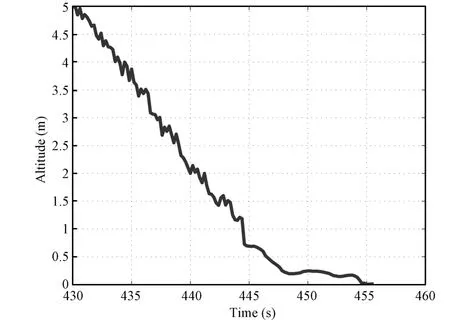
Fig.4.The vertical positioning results.
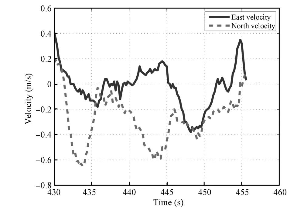
Fig.5.The attitude estimated during the landing process.

Fig.6.The velocities in two directions.
To furtherdemonstrate the proposed method,severallanding experiments have been conducted using the wavelet-adaptive KF and the EKF method used before.
Fig.7 shows the landing results using the wavelet-adaptive KF and the EKF,separately.The SUAR enters the landing mode roughly ten meters above the landing platform and then slowly descends until it has landed.The average Euclidean distances from the landing target are 63 cm and 101 cm, respectively.

Fig.7.The result of landing tests.
V.CONCLUSION
Focusing on the low measurementperformance of the sensor for the low cost SUAR,a navigation method based on vision was proposed to improve the accuracy and reliability of the measurement information.The nonlinear optimization based on Newton iteration method for camera attitude and position was put forward to reduce the projection error and get an optimized solution.With the wavelet filter method,the high frequency noises in the SINS and vision have been eliminated effectively.By using the adaptive Kalman filter,the system fuses the output from SINS and vision to get high precision navigation information.Finally,the landing tests show thatthe compound navigation system based on the proposed method can provide high performance navigation information.With the high performance position and attitude information,theSUAR can realize stable autonomous landing based on the altitude information.
REFERENCES
[1]Zhong Li-Na,Wang Jun-Hao,Wang Rong.Auto flight algorithm of quad-rotor helicopter based on magnetic sensor.Journal of Chongqing University of Technology(Natural Science),2013,27(12):86−90(in Chinese)
[2]Jiang Bin,Sun Zhi-Feng.The realization of autonomous navigation for quadrotor aircraft.Electronic Technology,2012,39(2):10−12,9(in Chinese)
[3]Najib M,Tarek H.A UAR for bridge inspection:visualservoing control law with attitude limits.AutomationinConstruction,2007,17(1):3−10
[4]Weiss S,Scaramuzza D,Siegwart R.Monocular-SLAM-based navigation for autonomous micro helicopters in GPS-denied environments. Journal of Field Robotics,2011,28(6):854−874
[5]Wendel J,Meister O,Schlaile C,Trommer G F.An integrated GPS/MEMS-IMU navigation system for an autonomous helicopter. Aerospace Science and Technology,2006,10(6):527−533
[6]Shin E H,El-Sheimy N.Accuracy improvement of low cost INS/GPS for land applications.In:Proceedings of the 2002 U.S.Inst.Navigation, National Technical Meeting.San Diego,CA USA:ION NTM,2002. 146−158
[7]Michael N,Fink J,Kumar V.Cooperative manipulation and transportation with aerial robots.Autonomous Robots,2011,30(1):73−86
[8]How J P,Bethke B,Frank A,Dale D,Vian J.Real-time indoor autonomous vehicle test environment.IEEE Control Systems Magazine, 2008,28(2):51−64
[9]Saripalli S,Sukhatme G S,Montgomery J F.AnExperimental Study of the Autonomous Helicopter Landing Problem—Experimental Robotics VIII.Berlin:Springer-Verlag,2003.466−475
[10]Hermansson J,Gising A,Skoglund M,Sch¨on.Autonomous Landing of an Unmanned Aerial Vehicle,Technical Report,Automatic Control, Linkopings Universitet,Sweden,2010.
[11]Johnson A E,Montgomery J F,Matthies L.Vision guided landing of an autonomous helicopter in hazardous terrain.In:Proceedings of the 2005 IEEE International Conference on Robotics and Automation.Barcelona, Spain:IEEE,2005.3966−3971
[12]Yu Z Y,NonamiK,Shin J,Demian C.3D vision based landing controlof a small scale autonomous helicopter.International Journal of Advanced Robotic Systems,2007,4(1):51−56
[13]Press W H,Teukolsky S A,Vetterling W T,Flannery B P.Numerical Recipes in C:the Art of Scientifi c Computing(Second edition).Cambridge:Cambridge University Press,1992.
[14]Sun Yan-Yue,He Xiao-Hai,Song Hai-Ying,Chen Wei-Long.A blockmatching image registration algorithm for video super-resolution reconstruction.Acta Automatica Sinica,2011,37(1):37−43(in Chinese)
[15]Wan Yu-Chai,Liu Xia-Bi,Han Fei-Fei,Tong Kun-Qi,Liu Yu.Online learning of binary classifiers for improving google image search results. ActaAutomatica Sinica,2014,40(8):1699−1708
[16]Chong Yan-Wen,Kuang Hu-Lin,Li Qing-Quan.Two-stage pedestrian detection based on multiple features and machine learning.Acta AutomaticaSinica,2012,38(3):375−381(in Chinese)
[17]Hu M K.Visual pattern recognition by moment invariants.IRE Transactions onInformationTheory,1962,8(2):179−187
[18]Latry C,Panem C,Dejean P.Cloud detection with SVM technique. In:Proceedings of the 2007 IEEE International Conference on Geoscience and Remote Sensing Symposium.Barcelona,Spain:IEEE,2007. 448−451
[19]Cristiani N,Shawe-Taylor J.AnIntroductiontoSupportVectorMachines and Other Kernel-based LearningMethods.Cambridge:Cambridge University Press,2000.
[20]Lei Xu-Sheng,Fang Jian-Cheng,Bai Lang,etc.Autonomous Taking Off and Landing Technology for the Small Unmanned Rotorcraft Vehicle Based on the Pilot Model,C.N.Patent 102289714B,December 2011. (in Chinese)

Cunxiao Miao Lecturer at the School of Mechanical Engineering,University of Science and Technology Beijing.He received the B.S.degree from Northeast University,China in 2006 and the Ph.D.degree from Beihang University,China in 2013.His research interests include navigation,identification,and control of unmanned aerial vehicles. Corresponding author of this paper.
Jingjing Li Assistant engineer at Beijing Aerospace Times Optical-electronic Technology Co., Ltd..She received her master degree from Beihang University in 2013.Her research interests include inertial navigation and visual navigation of unmanned aerial vehicles.
t
October 10,2013;accepted July 18,2014.This work was supported by China Postdoctoral Science Foundation(2013M540857) and Fundamental Research Funds for the Central Universities(FRF-TP-14-019A1).Recommended by Associate Editor Bin Xian
:Cunxiao Miao,Jingjing Li.Autonomous landing of small unmanned aerial rotorcraft based on monocular vision in GPS-denied area. IEEE/CAA Journal of AutomaticaSinica,2015,2(1):109−114
Cunxiao Miao is with the School of Mechanical Engineering,University of Science and Technology Beijing,Beijing 100083,China(e-mail: miao cunxiao@163.com).
Jingjing Li is with Beijing Aerospace Times Optical-electronic Technology Co.,Ltd(ATOT),Beijing 100094,China(e-mail:001rose001@sina.com).
 IEEE/CAA Journal of Automatica Sinica2015年1期
- IEEE/CAA Journal of Automatica Sinica的其它文章
- Guest Editorial for Special Issue on Autonomous Control of Unmanned Aerial Vehicles
- Continuous Sliding Mode Controller with Disturbance Observer for Hypersonic Vehicles
- Adaptive Backstepping Tracking Control of a 6-DOF Unmanned Helicopter
- A Predator-prey Particle Swarm Optimization Approach to Multiple UCAV Air Combat Modeled by Dynamic Game Theory
- Finite-time Attitude Control:A Finite-time Passivity Approach
- Decoupling Trajectory Tracking for Gliding Reentry Vehicles