Influence of tool pin profile on microstructure and corrosion behaviour of AA2219 Al
—Cu alloy friction stir weld nuggets Ch. VENKATA RAOa, G. MADHUSUDHAN REDDYb, K. SRINIVASA RAOa,*
Deprtment of Metllurgicl Engineering, Andhr University, Viskhptnm, IndiDefence Metllurgicl Reserch Lortory, Hyderd, IndiReceived 18 Mrch 2015; revised 21 April 2015; ccepted 21 April 2015 Aville online 29 My 2015
Influence of tool pin profile on microstructure and corrosion behaviour of AA2219 Al
—Cu alloy friction stir weld nuggets Ch. VENKATA RAOa, G. MADHUSUDHAN REDDYb, K. SRINIVASA RAOa,*
aDepartment of Metallurgical Engineering, Andhra University, Visakhapatnam, IndiabDefence Metallurgical Research Laboratory, Hyderabad, India
Received 18 March 2015; revised 21 April 2015; accepted 21 April 2015 Available online 29 May 2015
Abstract
To overcome the problems of fusion welding of aluminium alloys, the friction stir welding (FSW) is recognized as an alternative joining method to improve the mechanical and corrosion properties. Tool profile is one of the important variables which affect the performance of the FS weld. In the present work, the effect of tool profile on the weld nugget microstructure and pitting corrosion of AA2219 aluminium—copper alloy was studied. FSWof AA2219 alloy was carried out using five profiles, namely conical, square, triangle, pentagon and hexagon. The temperature measurements were made in the region adjacent to the rotating pin. It was observed that the peak temperature is more in hexagonal tool pin compared to the welds produced with other tool pin profiles. It is observed that the extensive deformation experienced at the nugget zone and the evolved microstructure strongly influences the hardness and corrosion properties of the joint during FSW. It was found that the microstructure changes like grain size, misorientation and precipitate dissolution during FSW influence the hardness and corrosion behaviour. Pitting corrosion resistance of friction stir welds of AA2219 was found to be better for hexagon profile tool compared to other profiles, which was attributed to material flow and strengthening precipitate morphology in nugget zone. Higher amount of heat generation in FS welds made with hexagonal profile tool may be the reason for greater dissolution of strengthening precipitates in nugget zone.
Copyright©2015, China Ordnance Society. Production and hosting by Elsevier B.V. All rights reserved.
Keywords:AA2219 Al—Cu alloy; Friction stir welding; Nugget zone; Microstructure; Electron backscattered diffraction; Pitting corrosion; Grain boundary misorientation
E-mail addresses: venkat.auce@gmail.com (Ch. VENKATA RAO), gmreddy_dmrl@yahoo.com (G. MADHUSUDHAN REDDY), arunaraok@ yahoo.com (K. SRINIVASA RAO).
Peer review under responsibility of China Ordnance Society
http://dx.doi.org/10.1016/j.dt.2015.04.004
2214-9147/Copyright©2015, China Ordnance Society. Production and hosting by Elsevier B.V. All rights reserved.
1. Introduction
Friction stir welding (FSW), an innovative solid state welding technique, has found a wide use in defence and aerospace applications [1]. This environment-friendly and energy-efficient technique can be used to join high strength aluminium alloys and other metallic materials that are difficult to be joined using conventional welding processes. In FSW, a rotating tool generates frictional heat, resulting in local plastic deformation [2]. Functions of two main parts of the tool; shoulder and the pin are generation of heat for material softening and material flow control for defect free weld. Generally of microstructure in a given zone of friction stir weld is strongly influenced by the peak temperature and material flow. It is also known that age hardenable AA2219 Al—Cu alloy is sensitive to microstructural changes during welding. Understanding of effect of material flow on the microstructural changes is very limited with respect to aluminium alloys [3—6]. Tool pin profile strongly influences the microstructure changes in weld nugget of friction stir welds and thus plays an important role in corrosion behaviour. The microstructure heterogeneity of friction stir welds is significant in determining the corrosion properties of AA2219 alloy owing to the galvanic coupling between the noble CuAl2precipitate and thesurrounding matrix [7—10]. Most of the previous investigations on the design of tool geometry were focused on optimizing the tool pin profile with respect to microstructure and mechanical properties [11—14]. A detailed review of tool design was reported on the geometrical features of the tool pin (including threads,flutes,flats, whorls,flares and skew on cylindrical or cone-frustum-shaped pins with rounded or flat bottom) and shoulder (including ridges, grooves, knurling and scrolls) [3,15]. However the studies related to the effect of tool profile on weld nugget microstructure and corrosion behaviour of welds are scarce. Keeping in view of the above facts, the present investigation is aimed at studying the microstructure changes in nugget zones and pitting corrosion behaviour of AA2219 alloy FS welds made with five tool profiles which are combination of smooth type conical and flat type triangle, square, pentagon and hexagon.
2. Material and methods
Inthepresentinvestigation,240mm×160mm×7mmrolled platesofhigh-strengthaluminium—copperalloy AA2219—T87 were used for friction stir welding experiments. The chemical composition of the parent metal is given in Table 1. The plates were welded in single pass, normal to the rolling direction, with square-butt joint configuration employing a position controlled FSW machine (ETA make). The initial joint configuration is obtained by securing the plates in position using the mechanical clamps. The tool material used in this study is hot worked die steel (AISI-H13). Experiments were conducted with different tool pin profiles, namely conical, triangular, square, pentagon and hexagon cross-sections (Fig. 1). The shoulder diameter was kept constant at 12 mm for all tools, thereby ensuring that the pin profile was only variation from tool-to-tool. Tool geometry details are given in Table 2.

Table 2Details of tool.

Fig. 1. Geometries of five tool profiles and weld joints made with five tools.
For FSW joints produced by different tool pin profiles, was identified through trial experiments. The geometries of the nugget and TMAZ were consistent for each pin profile. Based on the trial experiments, three thermocouples spaced 20 mm apart were embedded in the plates to be welded, so as to place the tip of the thermocouple at the nugget/TMAZ interface. A GRAPHTECH data logger GL900 was used to record the temperatures at the rate of 50 readings per second during welding. The average of the three temperature measurements is considered in this study. However, it is very difficult to measure the temperature directly in the stirred zone due to the severe plastic deformation produced by the rotation and translation of the tool. AA2219 FS-welded specimens were made for optical microscopy and scanning electron microscopy. Keller's reagent is used for etching the polished surfaces, and the optical micrographs are recorded. Specimens were sliced in 10 mm×10 mm size by using hacksaw, and these specimens were subjected to SEM studies. SEM micrographs were taken with secondary electron image mode at 15 kV and 30 kV. Scanning electron microscopy (SEM) was done for transverse section of the welds for five different tool profiles. Studies on strengthening precipitates were carried out using a 120 kV Tecnai-G2 transmission electron microscope. 10 mm×6 mm×0.5 mm slices were cut using low speeddiamond cutting machine. These slices were mechanically thinned to about 50 microns using emery papers. Subsequent electrolytic thinning was carried out by twin-jet electro-polishing in which an electrolyte consisting of a mixture of 10% perchloric acid and 90% methanol was used. During electrolytic thinning, the electrolyte temperature was maintained at about -40°C using liquid nitrogen. Electron backscattered diffraction (EBSD) is used to understand the microstructural evolution. Fei™Quanta-3D FEG (field emission gun) SEM (scanning electron microscope) with TSL-OIM™system was used for EBSD. EBSD was operated at an accelerating voltage of 20 kV, and imaging was performed at a step size of 0—1.0 μm. Line intercept method was employed for measurement of grain size. EBSD data were analysed to estimate grain size and in-grain misorientation. A grain was defined as an area bound by >5°misorientation. The hardnesses of the weld joints, which were carried with 0.2 kgf load along the mid-thickness of the joint perpendicular to the welding direction, were test using Vickers hardness tester. The indents were spaced at distance of 0.3 mm in accordance with ASTM E 384. Differential scanning calorimetry (DSC) was used to investigate the welds produced by each of the tool pin profiles, and 10 mg of metal was extracted from the stirred region. The extracted metal/specimen was heated at a heating rate of 40°C/min, from ambient temperature (35°C) to 550°C. The fraction of precipitates dissolved during friction stir welding was estimated. Software-based PAR basic electrochemical system was used for potentio-dynamic polarization test to study the pitting corrosion behaviour of weld nuggets of AA2219 FS welds. The test was carried out to determine the critical pitting corrosion potential Epitfrom the recorded polarization curve.
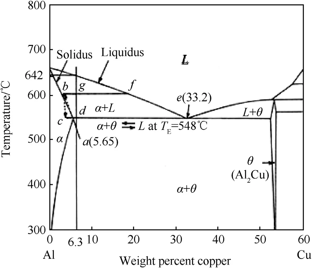
Fig. 2. Al—Cu phase diagram.

Fig. 3. Optical micrographs of AA2219 FS welds of nugget zone. a) Base metal; b) Conical; c) Triangle d) Square; e) Pentagon; and f) Hexagon.
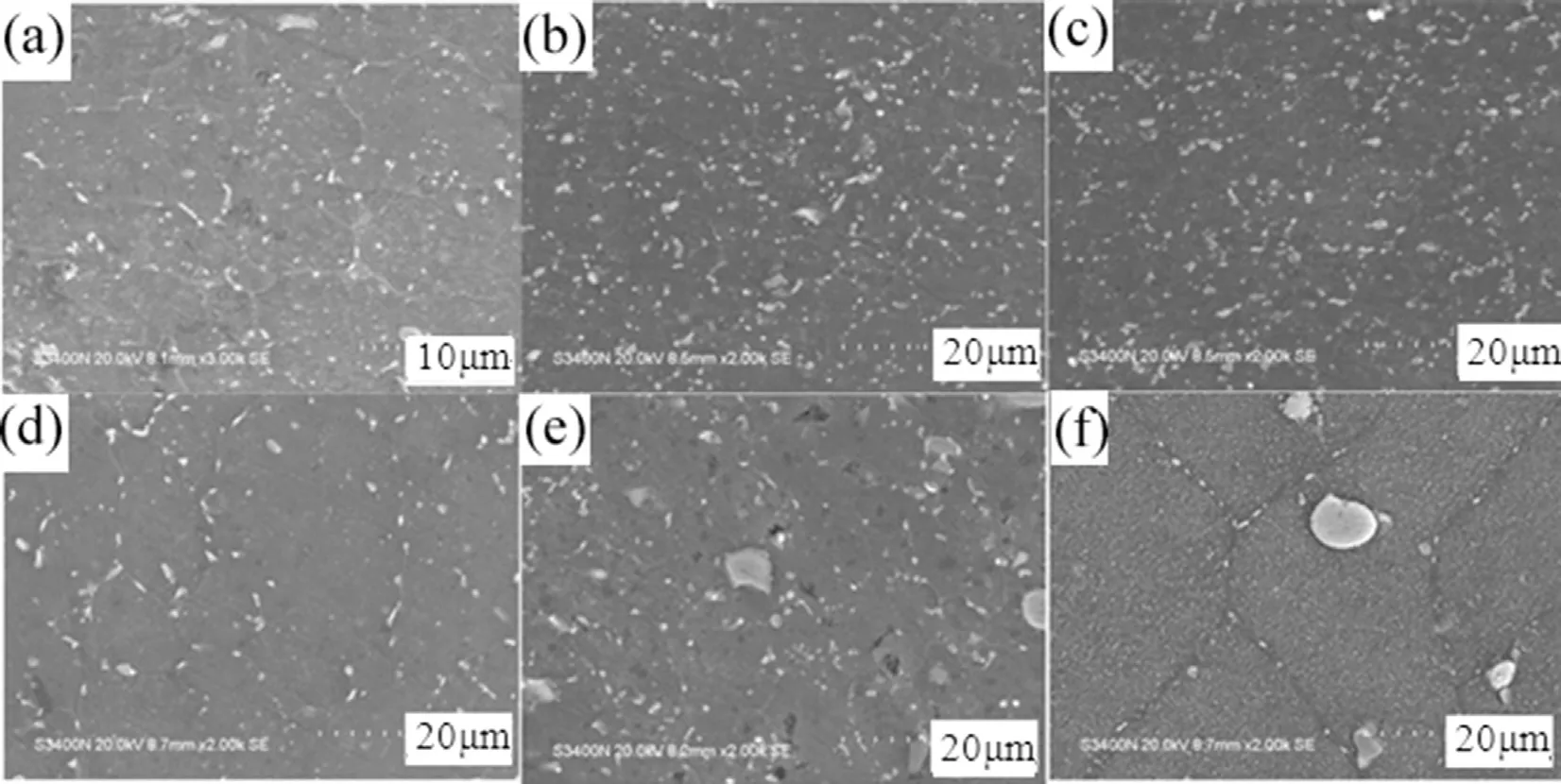
Fig. 4. Scanning electron micrographs of AA2219 FS welds of nugget zone. a) Base metal; b) Conical; c) Triangle; d) Square; e) Pentagon; and f) Hexagon.

Fig. 5. Transmission electron micrographs of AA2219 FS welds in nugget zone a) Base metal b) Conical c) Triangle d) Square e) Pentagon and f) Hexagon.
3. Results and discussion
3.1. Microstructure
Aluminium-rich portion of the Al—Cu phase diagram is shown in Fig. 2 The big gap between the solidus line and liquidus line indicates the Cu content of α phase (Al-rich solid) is much lower than that of the liquid. Since %Cu content is about 20 times higher or more than the content of any other alloying element, alloy AA2219 can be considered as a binary alloy of Al-6.3% Cu as an approximation. From the phase diagram the base metal is expected to consist of a α-matrix plus additional undissolved θ(CuAl2) particles [16]. During solution treating of the ingot, the large eutectic islands decompose into large θ particles and α. During rolling some of the large θ particles are displaced or even fractured.
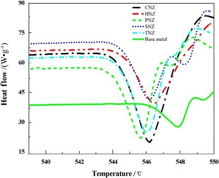
Fig. 6. DSC traces for weld nuggets of various tools.

Table 3Percentage of precipitates dissolved in FSW.
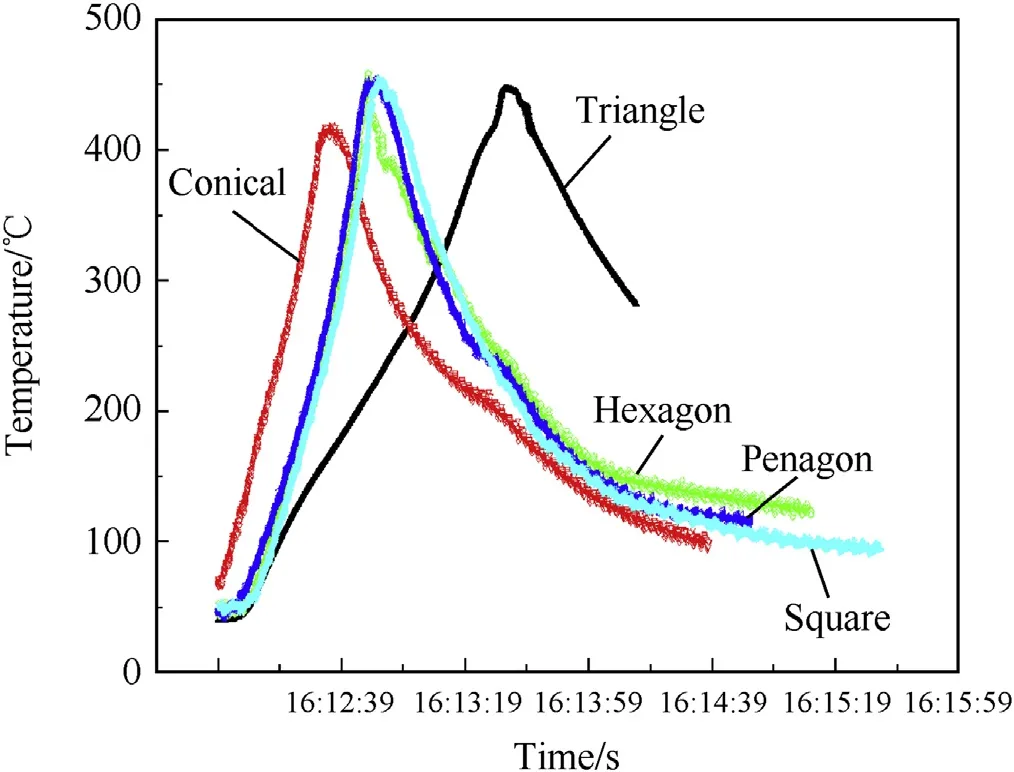
Fig. 7. Transient temperatures sensed by the thermocouples for different tool pin profiles.

Table 4Average peak temperatures for different tool profiles.
Optical micrographs of weld nugget made with five different tool profiles along with base metal are given in Fig. 3, where the grain boundaries are darkly etched and the primary strengthening precipitates are the metastable θ phase. Base metal microstructure reveals elongated grain characteristic of the rolled plate with some dark intermetallic particles. The prior thermal temper of the alloy affects the size and distribution of the phase microstructure consisting of white matrix of α-solid solution grains and second phase appearing black in colour. The nugget region has experienced high temperatures and extensive plastic deformation and is characterized by dynamically recrystallized grains. The deformation extent of the plastic material and the flow of the material affect the microstructure and the properties of the nugget. The pin geometry affects the weld nugget microstructure significantly. Specifically the weld made with hexagon tool profile (Fig. 3f) shows very fine grain distribution compared to other tool profiles, Very fine grains are formed in nugget zone of welds made with hexagon tool due to dynamic recrystallization compared to weld nugget made with other tools (Fig. 3b—f). Therefore, the shape of the weld nugget zone is only dependent on the shape and the geometry of welding tool, but not on the welding parameters.
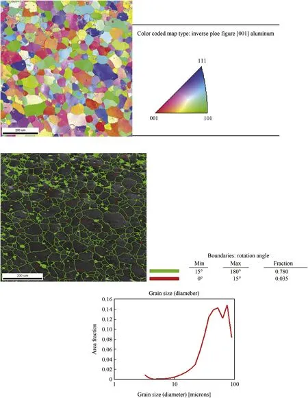
Fig. 8. Base metal EBSD and grain boundary misorientation.
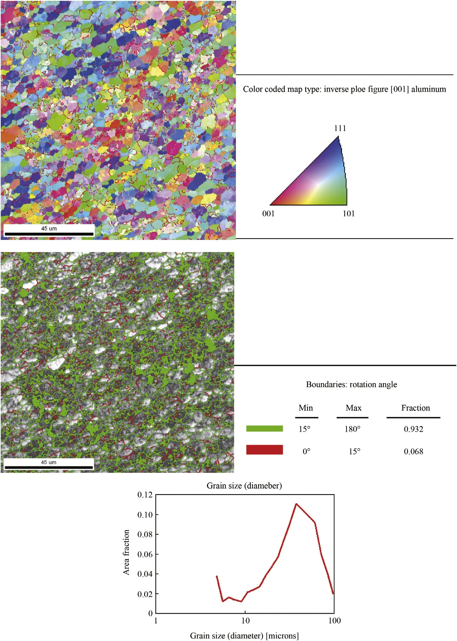
Fig. 9. Conical weld nugget EBSD and grain boundary misorientation.
The scanning electron micrographs of weld nugget zones of friction stir welds of AA2219-T87 alloy made with different profile tools are shown in Fig. 4. The large particles (2—10 μm) were present both within grains and at grain boundaries. From the phase diagram (Fig. 2.), the base metal is expected to consist of a α-matrix plus additional undissolved θ(CuAl2), particles [17]. As an approximation, these particles will be considered as the θ phase even though they may contain very small amounts of other elements as well. The optical and SEM photographs in the present study clearly reveals that the density of second phase particles is higher in cold worked (T87) condition. The grains and distribution of second phase particles were seen it was found that grain sizes are decreased from conical to hexagonal tool profiles. The second phase particles θ(CuAl2) in all tool profiles are more uniform and very small in the nugget zone made with hexagonal tool profile. The more the number of flats in tool are, the more the heat generates which may cause more degree of deformation than other tools low degree of deformation was found in case of smooth type conical tool.
The increase in degree of deformation during FSW results in the reduction in the recrystallized grain size according to the general principles of recrystallization the generalprinciples of recrystallization and contributes to the large brokening of bigger second phase particles. Disintegration of eutectic network in weld nugget clearly observed may be attributed to relatively more heat available in hexagon tool profile compared to other tool profiles. Several small particles within grains and along grain boundaries (GBs) were believed to be θ and θ′phase, as they were too small to be analysed by SEM. So further characterization tools like TEM and EBSD were employed to understand the microstructural changes and grain orientation.
The morphology of the precipitates is clearly visible in base metal. Transmission electron micrographs of weld nugget zones of friction stir welds of AA2219-T87 alloy made with smooth and flat type profile tools are shown in Fig. 5. The densely distributed plate-like semi-coherent and coherent strengthening precipitates θ′and θ′phases are observed in TEM micrographs of base metal. The TEM images of nugget zones are marked by the absence of well aligned disc shaped precipitates unlike the base material. This indicates the dissolution of second phase precipitates during the weld thermal cycle. TEM studies clearly revealed the morphology of precipitates (CuAl2) in weld nugget. Similarly relative higher rate of dissolution of precipitates was observed in the nugget zone of weld made with hexagon tool compared to that of other tools, which is due to higher amount of heat generation during FS welds using hexagon profile. This is strengthened by DSC and thermal studies.
3.2. Differential scanning calorimetry (DSC)
DSC studies were carried out to quantify the amount of precipitates dissolved in nugget zone during friction stirwelding. The DSC traces are shown in Fig. 6 for the five tool pin profile welds and the base metal. The graph clearly reveals that the endothermic peaks are obtained at temperatures between 542°C and 544°C, which corresponds to the complete dissolution of precipitates as observed from phase diagram. The amount of precipitates dissolved was estimated from DSC traces by considering the area within the endothermic peak corresponding to the precipitate dissolution for the particular tool pin profiled weld. The amount of precipitates dissolved during FSW is presented in Table 3. The calculation shows that the dissolution is relatively higher in the case of hexagon tool pin welds as compared to other tool pin profiled welds. This may be due to relatively higher peak temperature. These results in correlation with TEM.
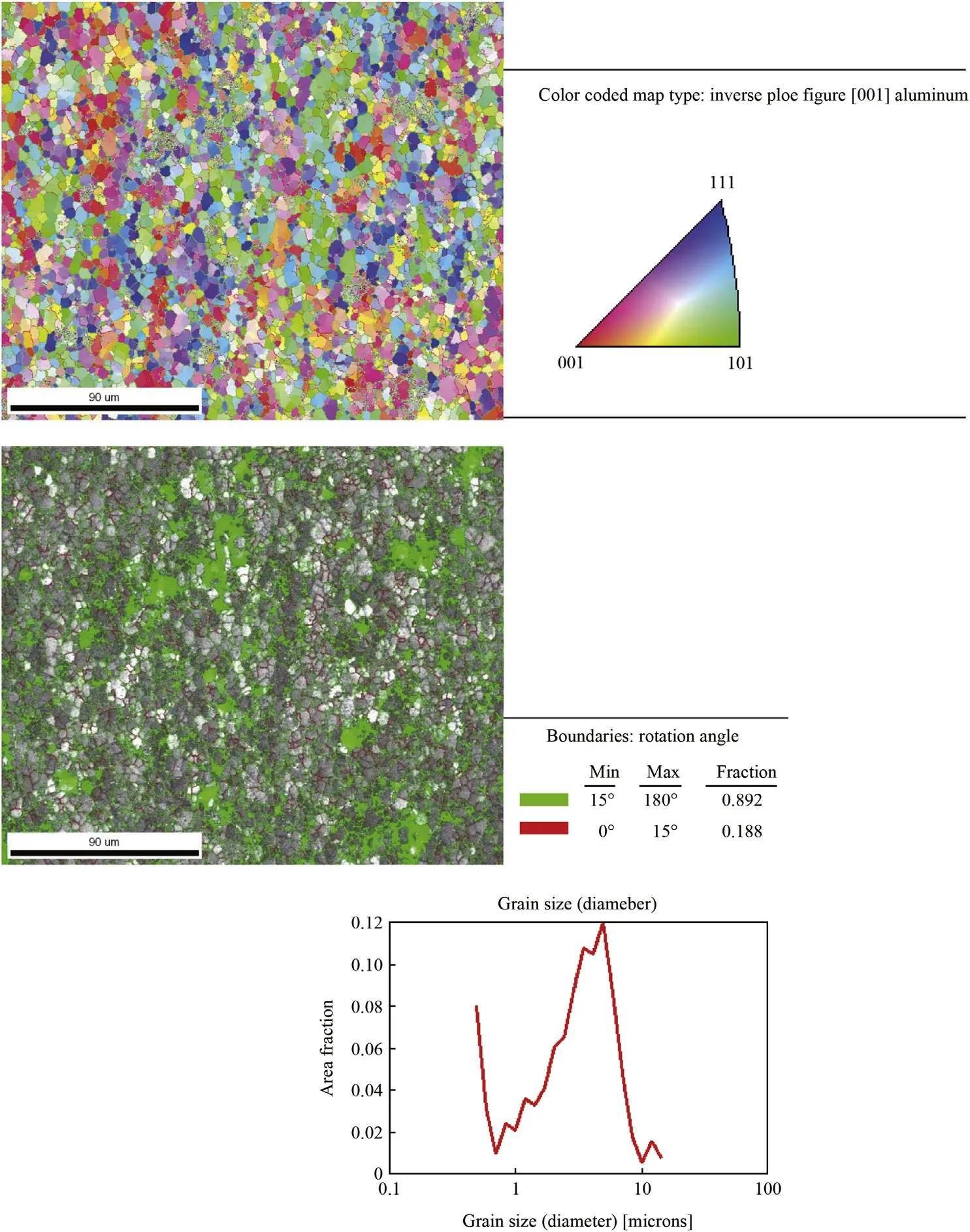
Fig. 11. Square weld nugget EBSD and grain boundary misorientation.
3.3. Temperature measurements
Average temperature measurements, with scatter of±4°C, are listed in Table 4. The typical transient temperatures sensed by the thermocouples were recorded for different tool pin profiles and are shown in Fig. 7, represents the variation in the measured temperatures with time. Peak temperature becomes higher by changing the tool pin profile from conical profile to hexagonal profile. It has been observed that the peak temperature is relatively more and the measured temperature rises at a rapid rate in the case of hexagonal tool pin profile compared to the welds produced using other tool pin profiles. In contrast, the conical pin profile displayed the slowest rate of temperature build-up with time.
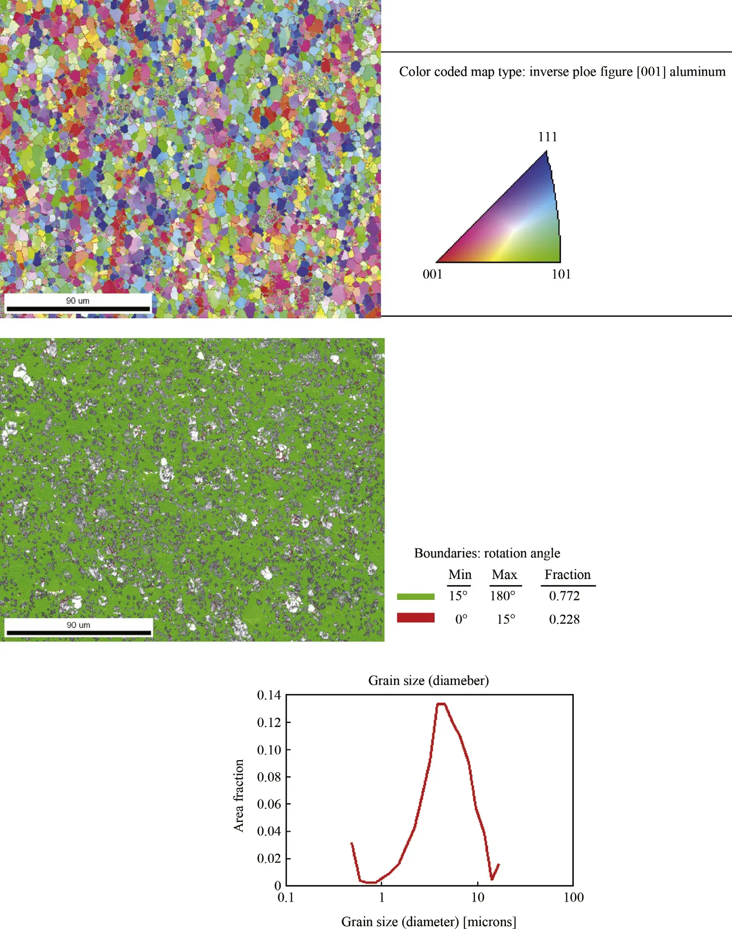
Fig. 12. Pentagon weld nugget EBSD and grain boundary misorientation.
3.4. Electron back scattered diffraction studies
EBSD analysisof microstructureclearly showed the different processeslikerecoveryorrecrystallizationofweldnuggetzones. Thesizesofgrainsinthewelds producedbyfivetoolpinprofiles weremeasuredusing EBSDthroughthelineinterceptmethod,as shown in Figs. 8—13. The grain size of weld nugget of hexagon profile was found to be very fine (0.67 μm) compared to that of other tool profiles. This may be attributed to higher amount of heat produced in hexagon tool profile. The grain sizes of weld nugget of various tool profiles are given in Table 5. High stackingfaultenergymaterials,suchasaluminiumalloy,undergo continuous dynamic recrystallization during high temperature deformation. Figs. 8—13 show the SEM/EBSD images of grain boundary misorientation in the five tool profiled weld nuggets of conical square, triangle, pentagon and hexagon, respectively. Dynamic recrystallization is caused by local frictional heating and severe plastic strain. Grain boundary misorientation has been divided into two classes, namely LAGBs (misorientation < 15deg.) and HAGBs,(misoriented>15deg.), and the values for different zones are given in Figs. 8—13. It is very clear that there is a substantial increase in the number of LAGBsofhexagontoolprofilecomparedtotheconicalandother toolprofiles.TheincreaseinLAGBscanbeattributedtodynamic recovery, whereby a large number of subgrains with low angle intergranular boundaries are formed.
3.5. Hardness studies
Several authors reported the hardness variations of weld nugget on different processing parameters [18—23]. In the present study, the hardness values in the weld nugget region wererecorded by Vicker hardness tester. The hardness values of weld nugget zones of various profiles are given in Tables 5 and 6. An examination of the data clearly demonstrates that the hardness valuesareconsiderablyaffectedbythegeometryoftoolpin.This may be attributed to fine grain microstructure in hexagonal tool profile due to sufficient heat and material flow available comparedtothatofweldmadewithothertoolprofiles.Thisresult isinagreementwiththegrainsizeandorientationmeasuredusing EBSD.
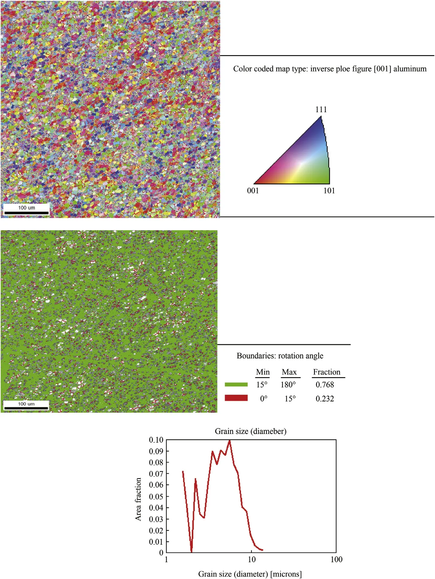
Fig. 13. Hexagon weld nugget EBSD and grain boundary misorientation.

Table 5Average grain sizes (microns) of weld nugget regions of AA2219 FS welds.
3.6. Pitting corrosion studies
The corrosion behaviour is attributed to the galvanic effect that could be understood from the polarization plots of the weld nugget. The potentio-dynamic polarization curves of the various tools of the weld nugget zones are shown in Fig. 14. The intermetallics are the initiation sites for pitting in Al—Cu alloys. The pitting is due to the local dissolution of the matrixas a result of galvanic coupling between intermetallics and surroundings matrix. The intermetallics containing Cu and Fe are cathodic with respect to the matrix, and promote the dissolution of the matrix. Better corrosion resistance of the weld nugget regions in 2xxx series aluminium alloys was reported earlier [24—26]. The dissolution of precipitates in the weld nugget seems to be the responsible factors for the improved corrosion resistance as well as the nobler corrosion potentials of this region. The pitting potential values of stir zones of AA2219 friction stir welds made with tool profiles of conical, triangle, square, pentagon and hexagon are given in Table 7. The weld nugget seems to have turned into a cathode and was completely protected from corrosion damage. It was clearly noticed that the relatively higher positive values Epitwere recorded in the nugget zone of the friction stir weld of hexagon tool profile. Clear demarcations in pitting corrosion resistance in weld nugget regions were observed. This is attributed to the dissolution of the strengthening precipitates in the nugget region. Pitting potential data clearly revealed the influence of tool profile on the correlation of microstructure changes to the pitting corrosion behaviour. As evident from the TEM and DSC observations, the percentage of precipitate formed was found to vary with tool profile which affected the peak temperature in the stir zone. An increased peak temperature (Fig. 7) in the stir zone resulted in the higher dissolution rate of precipitates and the retention of larger amount of solute in the matrix. Pitting potential value for stir zone made with hexagon tool is more positive compared to those of other tool profiles. Typical optical micrograph of the FSW specimens in Fig. 15 shows the extent of corrosion damage on the different tool profiles of the weldment. Pit density of weld nugget is more for conical profile compared to those of other profiles, which is in agreement with the observed pit potential values. Pit density of nugget zone of hexagon tool profile is relatively very low compared to those of other tool profiles. Hence it can be concluded that the improvement in pitting corrosion resistance can be achieved in the stir zones of friction stir welds of AA2219 alloy made with hexagonal tool.

Table 6Vickers hardness values (VHN) of 2219 Al -T87 alloys FS welds.
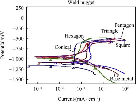
Fig. 14. Potentio-dynamic polarization curves of weld nugget AA2219 FS welds made with different profiles.

Table 7Pitting potential values of stir zones of AA2219 FS welds made with different tool profiles.
4. Conclusions
1) Tool geometry plays an important role in the weld nugget microstructure of AA2219 alloy FS welds. SEM studies revealed that the eutectic network disintegration and uniform distribution were obtained with hexagonal tool profile due to relatively higher heat generation.
2) DSC studies on FS welds of AA2219 alloy established that the rate of heat generation as well as the peak temperature and dissolution of precipitates were relatively higher in thecase of hexagon tool pin profile compared to other profiles. TEM studies also confirmed the higher dissolution of precipitates for hexagon tool.

Fig. 15. Micrographs of AA2219 FS welds in nugget zone after pitting corrosion (a) Base metal (b) Conical (c) Triangle (d) Square (e) Pentagon and (f) Hexagon.
3) EBSD analysis indicated that a continuous dynamic recrystallization process led to the formation of equiaxed grain structure in the weld nugget zone. Relatively more fine grain structure was found in hexagon tool profiled welds this may be lead to formation more LAGBs in the weld region.
4) The pitting corrosion resistance of the weld nugget was better than that of the parent AA2219 alloy in 3.5% NaCl solution and was attributed to the dissolution of the strengthening precipitates in the nugget region and the consequent reduction in the galvanic coupling.
5) Selection of tool profile is important in achieving the optimum combination of microstructure, hardness and corrosion properties of AA2219 aluminium—copper alloy friction stir welds. Hexagon profiled tool was found to be better option.
Acknowledgements
The authors would like to thank Dr.A.Ghokale, Director, Defence Metallurgical Research Laboratory, and Hyderabad, India for his continued encouragement and permission to publish this work.
References
[1] Thomas WM, Nicholas ED, Needham JC, Murch MG, Temple smith P, Dawas CJ. InternationalPatentApplication No. PCT/GB92/02203 and GB Patent Application No.9125978.8, Dec. 1991, U.S Oct. 1995: Patent Appl.No.5460317.
[2] Nandan R, DebRoy T, Bhadeshia HKDH. Recent advances in friction-stir welding process weldment structure and properties. Prog Mat Sci 2008;53:980—1023.
[3] Mishra RS, Ma ZY. Friction stir welding and processing. Mater Sci Eng R 2005;50:1—78.
[4] Thomas WM, Nicholas ED. Friction stir welding for the transportation industries. Mater Des 1997;18:269—73.
[5] Threadgill PL, Leonard AJ, Shercliff HR, Withers PJ. Friction stir welding of aluminium alloys. Int Mater Rev 2009;54(2):49—93.
[6] Chao YJ, Qi X, Tang W. Heat transfer in friction stir welding: experimental and numerical studies. ASME J Manufact Sci 2003;125:138—45.
[7] Thomas WM, Johnson KI, Wiesner CS. Friction stir welding—recent developments in tool and process technologies. Adv Eng Mat 2003;5:485—90.
[8] Zhao Yan-hua, Lin San-bao, Wu Lin, Qu Fu-xing. The influence of pin geometry on bonding and mechanical properties in friction stir weld 2014 Al alloys. Mat Let 2005;59(23):2948—52.
[9] Junhui Yan M, Sutton A, Reynolds AP. Process—structure—property relationships for nugget and heat affected zone regions of AA2524—T351 friction stir welds. Sci Technol Weld Join 2005;10(6):725—36.
[10] K. Surekha, Murty BS, Prasad Rao K. Effect of processing parameters on the corrosion behaviour of friction stir processed AA 2219 aluminium alloy. Solid State Sci 2009;11:907.
[11] Huang C, Kou S. Partially melted zone in aluminum welds-liquation mechanism and directional solidification. Weld J 2000;79:113s—20s.
[12] Hattingh DG, Blignault C, Van Niekerk TI, James MN. Characterization of the influences of FSW tool geometry on welding forces and weld tensile strength using an instrumented tool. J Mater Process Technol 2008;203(1—3):46—57.
[13] Ramanjaneyulu K, MadhusudhanReddy G, VenugopalRao A, Markandeya R. Structure-property correlation of AA2014 friction stir welds—role of tool pin profile. J Mater Eng Perform 2013;22:2224—40.
[14] Midling OT, Oosterkamp LD, Bersaas J. Friction stir welding aluminum—processandapplications.In:Proceedingsofthe7thinternationalconference joints in aluminium (INALCO'98), Cambridge, England, vol. 2, 161—171.
[15] Fuller CB. Friction stir tooling-tool materials and design. In: Mishra Rajiv S, Mahoney Murray W, editors. Friction stir welding and processing. Materials park, Ohio: ASM International; 2007. p. 7—36.
[16] Ringer’SP, Sakurap T, Polmear IJ. Origins of hardening in aged al-cumg-(ag)alloys. Acta Materilia 1997;45(No. 9):3731—44.
[17] Polmear IJ. Control of precipitation processes and properties in aged aluminum alloys by trace element additions. In: Proc.6th Int. Conf. on Aluminum Alloys (ICAA6), Toyohashi; 1998. p. 75—86.
[18] Zhang Huijie, Liu Huijie, Yu Lei. Thermal modeling of underwater friction stir welding of high strength aluminum alloy. Trans Nonferrous Metals Soc China 2013;23(4):1114—22.
[19] Liu Huijie, Zhang Huijie, Pan Qing, Yu Lei. Effect of friction stir welding parameters on microstructural characteristics and mechanical properties of 2219-T6 aluminum alloy joints. Int J Mater Form 2012;5(3):235—41.
[20] Feng Xiuli, Liu Huijie, Babu Sudarsanam Suresh. Effect of grain size refinement and precipitation reactions on strengthening in friction stir processed Al-Cu alloys. Scr Mater 2011;65(12):1057—60.
[21] Zhang HJ, Liu HJ, Yu L. Microstructure and mechanical properties as a function of rotation speed in underwater friction stir welded aluminum alloy joints. Mater Des 2011;32(8—9):4402—7.
[22] Zhang HJ, Liu HJ, Yu L. Microstructural evolution and its effect on mechanical performance of the joint in underwater friction stir welded 2219-T6 aluminumalloy. Sci Technol Weld Join 2011;16(5):459—64.
[23] Liu HJ, Zhang HJ, L. Yu. Effect of welding speed on microstructures and mechanical properties of underwater friction stir welded 2219 aluminum alloy. Mater Des 2011;32(3):1548—53.
[24] SrinivasaRaoand K, PrasadRao K. Pitting corrosion of heat-treatable aluminium alloys and welds: a review. Trans Indian Inst Metals 2004;576:5593—610.
[25] Koteswara Rao SR, Madhusudhana Reddy G, Srinivasa Rao K, Kamaraj M, Prasad Rao K. Reasons for superior mechanical and corrosion properties of 2219 aluminum alloy electron beamwelds. Mater Charact 2006;40(4-5):236—48.
[26] SrinivasaRao K, Madhusudan Reddy G, Prasad Rao K. Studies on partially melted zone in aluminium—copper alloy welds—effect of techniques and prior thermal temper. Mater Sci Eng (A) 2005;403:69—76.
* Corresponding author.
- Defence Technology的其它文章
- Gas tungsten arc welding of ZrB2
—SiC based ultra high temperature ceramic composites R.V. KRISHNARAO*, G. MADHUSUDHAN REDDY - Optimization of process parameters of aluminum alloy AA 2014-T6 friction stir welds by response surface methodology Ramanjaneyulu KADAGANCHIa, Madhusudhan Reddy GANKIDIb,*, Hina GOKHALEb
- Effect of hot-humid exposure on static strength of adhesive-bonded aluminum alloys
- Numerical modeling of friction stir welding using the tools with polygonal pins M. MEHTAa, G.M. REDDYb, A.V. RAOb, A. DEc,*
- Microstructure and pitting corrosion of shielded metal arc welded highnitrogen stainless steelRAFFI MOHAMMEDa, G. MADHUSUDHAN REDDYb, K. SRINIVASA RAOa,*
- Characterization of magnetically impelled arc butt welded T11 tubes for high pressure applications R. SIVASANKARIa, V. BALUSAMYa, P.R. VENKATESWARANb,*, G. BUVANASHEKARANb, K. GANESH KUMARb

