
Optimization of process parameters of aluminum alloy AA 2014-T6 friction stir welds by response surface methodology Ramanjaneyulu KADAGANCHIa, Madhusudhan Reddy GANKIDIb,*, Hina GOKHALEb
2015-07-02 06:14:02MhtmGndhiInstituteofTechnologyHyderdIndiDefenceMetllurgiclReserchLortoryHyderdIndiReceived22Ferury2015revised29Mrch2015ccepted30Mrch2015AvilleonlineMy2015
Defence Technology 2015年3期
Mhtm Gndhi Institute of Technology, Hyderd, IndiDefence Metllurgicl Reserch Lortory, Hyderd, IndiReceived 22 Ferury 2015; revised 29 Mrch 2015; ccepted 30 Mrch 2015 Aville online 1 My 2015
Optimization of process parameters of aluminum alloy AA 2014-T6 friction stir welds by response surface methodology Ramanjaneyulu KADAGANCHIa, Madhusudhan Reddy GANKIDIb,*, Hina GOKHALEb
aMahatma Gandhi Institute of Technology, Hyderabad, IndiabDefence Metallurgical Research Laboratory, Hyderabad, India
Received 22 February 2015; revised 29 March 2015; accepted 30 March 2015 Available online 1 May 2015
Abstract
The heat treatable aluminum—copper alloy AA2014 finds wide application in the aerospace and defence industry due to its high strength-toweight ratio and good ductility. Friction stir welding (FSW) process, an emerging solid state joining process, is suitable for joining this alloy compared to fusion welding processes. This work presents the formulation of a mathematical model with process parameters and tool geometry to predict the responses of friction stir welds of AA 2014-T6 aluminum alloy, viz yield strength, tensile strength and ductility. The most influential process parameters considered are spindle speed, welding speed, tilt angle and tool pin profile. A four-factor,five-level central composite design was used and a response surface methodology (RSM) was employed to develop the regression models to predict the responses. The mechanical properties, such as yield strength (YS), ultimate tensile strength (UTS) and percentage elongation (%El), are considered as responses. Method of analysis of variance was used to determine the important process parameters that affect the responses. Validation trials were carried out to validate these results. These results indicate that the friction stir welds of AA 2014-T6 aluminum alloy welded with hexagonal tool pin profile have the highest tensile strength and elongation, whereas the joints fabricated with conical tool pin profile have the lowest tensile strength and elongation.
Copyright©2015, China Ordnance Society. Production and hosting by Elsevier B.V. All rights reserved.
Keywords:Friction stir welding; Aluminum alloy AA 2014-T6; Mechanical properties; Optimization of process parameters; Response surface methodology
E-mail address: gmreddy_dmrl@yahoo.co.in (M.R. GANKIDI).
Peer review under responsibility of China Ordnance Society.
http://dx.doi.org/10.1016/j.dt.2015.03.003
2214-9147/Copyright©2015, China Ordnance Society. Production and hosting by Elsevier B.V. All rights reserved.
1. Introduction
The fusion welding of heat treatable aluminum alloys has always been a great challenge for designers and technologists. The difficulties associated with these joints are presence of a tenacious aluminum oxide, high thermal conductivity, high coefficient of thermal expansion, solidification shrinkage, and adsorbed gases in molten aluminum [1]. In fusion welding, formation of brittle inter dendritic structure occurs due to eutectic melting and resolidification of the fusion zone, which results in decreasing in the mechanical properties like lower strength, hardness and ductility [2,3]. In addition to the above, the high strength aluminum alloys AA 2014 are prone to solidification cracking. Therefore, the fusion welding processes are not suitable for joining these alloys.
Friction Stir Welding (FSW) is a solid state joining technique developed by TWI, Cambridge, in 1991 [4]. FSW is immune to the defects and property deteriorations such as melting, solidification, dissolution and or coarsening of precipitates and softening of heat affected zone. In addition, the extensive thermomechanical deformation induces dynamic recovery and dynamic recrystallization that refine the weld microstructure [5]. Therefore, FSW welds have shown the improved mechanical properties compared with fusion welds [6—8]. The present research work focuses on the development of mathematical models to predict the mechanical properties (yield strength, tensile strength and percentage elongation) of FSW joints of aluminum alloy AA2014 and to study theeffects of various process parameters, viz., tool rotational speed, welding speed, tilt angle and tool pin profile, on the mechanical properties of friction stir welded joints.
2. Experimental work
2.1. Identifying the important process parameters
The primary process parameters affecting the mechanical properties, yield strength, tensile strength and percentage elongation were chosen through literature search and several preliminary lab experimentations. These parameters were found as rotational speed (x1), welding speed (x2), tilt angle (x3) and tool pin profile (x4) [9—17] (see Fig. 1).

Fig. 1. Cause and effect diagram used for selection of process parameters for optimization.
2.2. Determining the working range of process
parameters
Several trial experiments were carried out on 5 mm thick AA 2014-T6aluminumalloytofindoutthefeasibleworkingrangeof process parameters. Different combinations of process parameters were used to carry out trial experiments for determining the working range of each process parameters. These ranges of processparametersweredeterminedinsuchawaythatthe joints were free from defects. The ranges were fixed using microstructure features of the weld cross sections. The following observations were made on the microstructure features:
a) When the rotational speed was less than 600 rpm, no sufficient heat was generated and the FSW tool got stuck in the material and it was not possible to carry out the welding. Warm hole at the retreating side of the weld nugget was observed, as shown in Fig. 2, which may be due to insufficient heat generation and correspondingly improper material flow. On the other hand, at rotational speed higher than 1400 rpm, an excess heat was generated during welding, resulting in the turbulence of material flow which leads to the formation of fine aluminum powder.

Fig. 2. Warm hole at the retreating side of the weld nugget during FSW with low rotational speed.
b) When the welding speed was less than 200 mm/min, at
constant rotational speed, the excess heat was generated, which resulted in turbulent material flow. When the welding speed was higher than 1000 mm/min, a warm hole at the retreating side was observed due to inadequate flow of material caused by insufficient heat input.
c) When the tilt angle was lower than 1.5°, the tunnel and crack like defects were observed in the middle of the cross section, due to the improper consolidation of the material and the insufficient downward force; When the tool tilt was increased above 3.5°, the excess flash and thinning of the weld due to excessive penetration of the shoulder into the weld were observed.
d) Tool profile is the secondary process parameter, which purely influences material flow during welding. The profiles of five different tools were chosen viz. conical, triangular, square, pentagon and hexagon with constant dynamic volume. The tools are made from H-13 tool steel. Appearance details are provided in Fig. 3. All these tool profiles produced sound welds. The cross sections of the welds produced by different tool profiles were subjected to metallographic examination to observe the microstructure. It is clear from the microstructure that the weld produced by conical profile was subjected to frictional force (material drag) exerted by the tool, and the friction dominated material flow was observed. Whereas the welds producedby hexagonal tool profile showed shear deformation, and the weld nugget was subjected to excessively worked microstructure due to the pulsating effect of the tool profile, which resulted in the better mechanical properties of the joint (Fig. 4).

Fig. 3. Geometry of various tool pin profiles.

Fig. 4. Microstructures showing the TMAZ/Weld Nugget inter face and weld nuggets.
AA2014-T6 with 5 mm thick aluminum alloy plates were cut into the required size (300 mm×80 mm) and the thickness side was machined to get square butt joint configuration for fabrication of FSW joints. The position controlled Friction stir welding machine (ETA make Bangalore) was used for welding, as shown in Fig. 5. The analyzed chemical composition and mechanical properties of the base metal are provided in Table 1. The welding direction is perpendicular to the rolling direction of the plate.
The process parameters and their working range are given in Table 2. Central composite design was chosen with four process parameters varying at five levels [18]. Based on the design matrix, 30 sets of experimental conditions and corresponding responses are presented in Table 3. First 16 experimental conditions are derived from full factorial design (24= 16). All the variables at the intermediate (0) level constitute the center points while the combination of each process variable at either their lowest (-2) or highest (+2)level with the other three variables at intermediate levels constitute the star points. Thus the 30 experimental conditions allowed the estimation of the linear, quadratic and two-way interactive effects of the process parameters on the responses (yield strength, tensile strength and elongation) of friction stir welded joints. Friction stir welding is carried out as per the design matrix at random to avoid any error creeping into the system. The macrographs of friction stir weld surfaces are shown in Fig. 6. The transverse tensile specimens were extracted from the weld joints by electro discharge machining (EDM), prepared and tested on Instron (Model No.1100) universal testing machine as per ASTM E8M-04 standards. The yield strength, ultimate tensile strength and percentage elongation are evaluated and the average of the three specimens is presented as the responses in Table 3.

Fig. 5. Friction stir welding machine.

Table 1Analyzed chemical composition and mechanical properties of AA 2014 aluminum alloy.

Table 2Process parameters and their working range.
3. Developing mathematical model
3.1. Response surface methodology
Response surface methodology (RSM) is a collection of mathematical and statistical techniques useful for analyzing the problems in which several independent variables influence a response. The objective of the response surface methodology is to find those settings of process parameters that give an optimum value of the response. In addition, it provides a regression model that establishes relationship between the process parameters and response. This relationship can be used to predict the response when the process parameters are varied within the selected ranges. The regression model geometrically represents surface, when plotted as response versus any two process parameters. Such plots make it possible to visualize the relation between the response and process parameters. Contour plots for corresponding response surface facilitate visually to locate the process parameter values that give optimum response.
The above-mentioned regression model or the response surface model is the form of

where y = either Y.S or UTS or Percentage elongation as case may be x1-tool rotational speed, x2-tool traverse speed, x3-tilt angle, x4-tool profile.

Table 3Design matrix with responses (mechanical properties of welds).

Fig. 6. Macrographs of friction stir weld surfaces of the welds carried out based on design matrix (rotational speed-travel speed-tilt angle—tool profile).
3.2. Checking for adequacy of model
The adequacy of the developed model is tested using the analysis of variance (ANOVA) technique and the results of second order response surface model fitting in the form of analysis of variance. ANOVA for yield strength, tensile strength and percentage elongation are shown in Tables 4—6 respectively. If the calculated value of Fratioof the developed model is less than the standard Fratio(from F-table) value at a desired level of confidence 95%, then the model is said to be adequate within the confidence level. The value of prob > F for three developed models is less than 0.05 (95% Confidence level), which indicates that the model is significant and lack of fit is not significant, as desired [9,15—19]. The normal percentage probability vs residual plots for yield strength, ultimate tensile strength percentage elongation are shown in Fig. 7 which reveals that the residuals are falling on straight line, which means the errors are distributed normally [20]. The experimental value vs predicted value of the responses from regression equations are presented in Fig. 8, which reveals that there is very good correlation between the experimental value and predicted value of the responses. All the above considerations indicate an excellent adequacy of the regression models.
All the coefficients were estimated and tested by applying ‘F-test’using trial version of Design-Expert software for their significance at a 95% confidence level. After determining the significant coefficients, the final model was developed to predict the yield strength (Eq (2)), ultimate tensile strength (Eq
(3)) and percentage elongation (Eq (4)) of FSW joints of AA2014 aluminum alloy as given below:


3.3. Optimizing the process parameters
In order to determine the process parameter values that give optimum response, contour plots were used. These are plotted for each response vs any of the two influential process parameters, while keeping other parameters as constant. These response contours can help in the prediction of the responses at any zone of the experimental domain. A contour plot is produced to visually display the region of optimal factor settings. Once the stationary point is found, it is usuallynecessary to characterize the response surface in the immediate vicinity of the point. Characterization is to identifying whether the stationary point found is maximum or minimum response or saddle point. Contour plots play very important role in the study of the response surface. Trial version of Design-Expert software is used to optimize the process parameters for obtaining the maximum responses (mechanical properties).
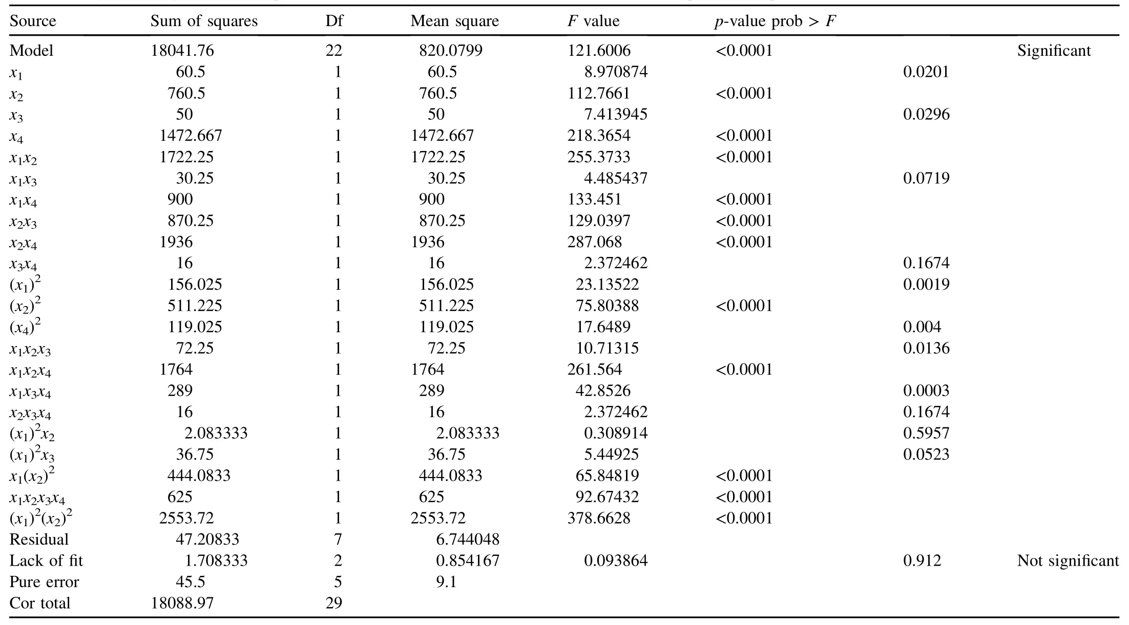
Table 4ANOVA for yield strength (Reduced quartic model). Analysis of variance table (Partial sum of squares—Type III).

Table 5ANOVA for ultimate tensile strength (Surface quadratic model).
3.4. Confirmation test
Confirmation experiments were conducted at the optimum settingofprocessparameters.Rotationalspeed (x1= 1000 rpm), traverse speed (x2= 800 mm/min), tilt angle (x3= 3.50) and Tool Profile (x4= Hexagon) were set, and the average tensile strength of friction stir welded AA 2014-T6 aluminum alloy was found to be 435 MPa, which was withinthe confidence interval of the predicted optimal tensile strength. Average yield strength and percentage elongation were also evaluated at their optimal conditions, and their values obtained were in the confidence interval.

Table 6ANOVA for percentage elongation (Quadratic model).
4. Results and discussion
From the regression models, the effects of friction stir welding process parameters viz. tool rotational speed, welding speed, tool tilt angle and tool profile on yield strength, ultimate tensile strength and percentage elongation of friction stir welded joints were evaluated. The four operating parameters considered directly affect on generation of frictional heat and causes the plastic flow of the material. It is observed that when the combinations of parameters create very low or very high frictional heat and material flow, then lower tensile strength is observed. The friction stir welding process leads to the clustering of the strengthening precipitates in the regions of TMAZ, HAZ and weld nugget. Therefore, the friction stir welded joints of aluminumalloys have lower tensileelongation than that of the base metal. The decrease in elongation is also due to localization of strain occurring in the regions softened by the welding process resulting in a comparatively low overall strain-to-failure, i.e. elongation [21]. When the combination of operating parameters increase the plastic flow of material and the frictional heat, then a corresponding decrease in the tensile elongation of the joints was observed. The possible causes for the effects of different welding parameters on tensile strength and tensile elongation are interpreted as follows.
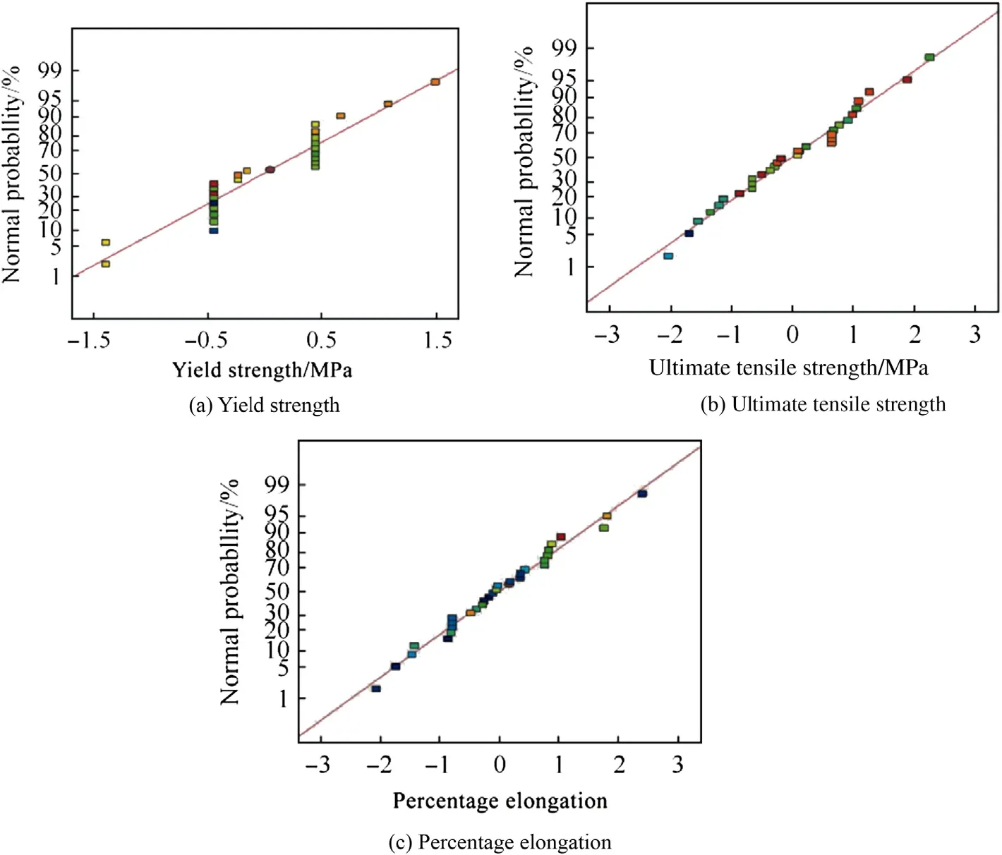
Fig. 7. Normal plots of residuals for the responses.

Fig. 8. Experimental vs predicted values of the responses.

Fig. 9. Effects of tool rotation speed and traverse speed on yield strength.

Fig. 10. Effects of traverse speed and tool profiles on yield strength.
4.1. Effect of process parameters on yield strength
The significant terms identified based on Eq. (2) are tool traverse speed (x2), tool profile (x4) interaction effect of tool rotational speed and traverse speed (x1x2), traverse speed and tilt angle (x2x3), traverse speed and tool profile (x2x4), tilt angle and tool profile (x3x4) etc. The negative co-efficient of tool rotational speed indicates that the yield strength decreases with increase in rotational speed, as shown in Fig. 9. Similarly as the traverse speed increases, the yield strength increases as shown in Fig. 10.
Arbegast explained a relationship between tool rotational speed and tool traverse speed at that heat index is proportional to tool rotational speed and inversely proportional to tool traverse speed [22].

where T is peak temperature, Tmis the melting point of the material,‘ω’is rotational speed in rpm,‘ϑ’is travel speed in inch/min,‘K’and‘α’are material constants and here are considered as 0.75 and 0.06, respectively. Increased heat index or heat input results in the metallurgical transformation, such as dissolution and coarsening of strengthening precipitates in the weld zone [23], and the lowering of dislocation density which decreases the yield strength of the friction stir welded joints [24—26]. The yield strength increase marginally with increase in tilt angle. As the tilt angle increases, the increase in consolidation of the material during welding results in the increased yield strength.
Pin profile plays a crucial role in material flow and in turn regulates the welding speed of the FSW process. Friction stir welds are characterized by well-defined weld nugget and flow contour. These contours are dependent on the tool design and welding parameters. Oosterkamp et al. identified the role of tool pin in the FSW, and the tool pin is to extrude the material from advancing side and forge at retreating side during translation of the tool [25]. The primary functions of the tool pin are to stir and plasticize the metal and move behind it to form sound joint. The joints fabricated by hexagon tool profile exhibit the highest yield strength irrespective of welding parameters. The tools with noncircular profiles are associated with eccentricity during friction stir welding (due to flat faces). This eccentricity allows hydro-mechanically incompressible plasticized material to flow more easily around the pin. Essentially it is the ratio of the static volume (physical volume) of the pin to dynamic volume (volume generated during rotation and it is strongly dependent on pin geometry) of the pin providing a path for the plasticized material to flow from the leading edge (Advancing side) to the trailing edge (retreating side). Moreover, the eccentricity of the lobes of noncircular pins assisting the breaking up of the oxides and fine grain structure in the nugget is the basis for better tensile properties. The tool pin profile with flat faces produces the pulsating effect and better plastic flow of material [15]. Therefore, the friction stir welding tools with 3, 4, 5 and 6 faces, viz. triangle, square, pentagon and hexagon produce the joints with increasing order of tensile properties [27]. There is no pulsating effect in the case of conical tool pin which produces the joints with lesser tensile properties. Ratio of pin volume to swept volume and number of pulses for each tool profile are shown in Table 7.

Table 7Ratio of pin volume to swept volume and no. of pulses for each tool profile.

Fig. 11. Effects of tool rotational speed and traverse speed on tensile strength.

Fig. 12. Effects of traverse speed and tilt angle on tensile strength.
4.2. Effect of process parameters on ultimate tensile strength
The significant terms identified based on Eq. (3), are tool traverse speed (x2), tool profile (x4), interaction effect of tool rotational speed & traverse speed (x1x2), traverse speed & tilt angle (x2x3), traverse speed & tool profile (x2x4), and tilt angle & tool profile (x3x4).
Based on Eq. (3) and Fig. 11, the effects of tool rotational speed and traverse speed on ultimate tensile strength can be analyzed, the increase in tool rotational speed with traverse speed resulted in the increased tensile strength of friction stirwelded joints. From Eq. (3), it can be noticed that lower the rotational speed the better is the UTS.
The effects of traverse speed and tilt angle on tensile strength are shown in Fig. 12. UTS is lower at 200 mm/min and reaches maximum at 600 mm/min and after that there is a decreasing trend in UTS. It may be due to higher heat input at lower traverse speed and reaches an optimum heat input at 600 mm/min. Further increase in traverse speed (above 600 mm/min) results in insufficient plastic flow of the material around the tool due to excess heat generated. The increased tensile strength was observed with increase in tilt angle (from 1.5°to 3.5°) and tool profile (from conical to hexagon). As the tilt angle increases, the frictional heat increases and the plasticized material under the shoulder is better consolidated. Tilt angle also improves the tool life by decreasing the thrust on the tool compared to 0°tilt and by increasing the tool tilt, and several welding defects can be eliminated, like pin-hole, formation of cavity, and tunnel type defects. The interactive effect of traverse speed and tool profile on tensile strength is shown in Fig. 13 and the interactive effect of tilt angle and tool profile on tensile strength is shown in Fig. 14. From Figs. 13 to 14 it can be concluded that, as the traverse speed and tilt angle increases above 600 mm/min and above 2.5°, respectively, without circular tool pin (hexagon), the tensile strength can reach to 420 MPa.

Fig. 13. Effects of traverse speed and tool profile on tensile strength.

Fig. 14. Effects of tilt angle and tool profile on tensile strength.
4.3. Effect of process parameters on percentage elongation
The significant terms identified based on Eq. (4), are tool tilt angle (x3), tool profile (x4), interaction effect of tool rotational speed & traverse speed (x1x2), tilt angle & tool profile (x3x4). From Eq. (4) it can be observed that the effects of tool rotational speed and tool traverse speed on percentage elongation are negligible. The interactive effect of tool rotational speed and traverse speed on percentage elongation is shown in Fig. 15. The interactive effect of tilt angle and tool profile on percentage elongation is shown in Fig. 16. Increase in tilt angle resulted in proper consolidation of the material under the shoulder and non circular (hexagon) tool profiles yielded worked microstructure which gives high ductility. The welds carried out using hexagon tool have the highest percentage elongation whereas the joint using conical tool profile showed the lowest percentage elongation.

Fig. 15. Effect of tool rotational speed and traverse speed on percentage elongation.
5. Conclusions
1) Regression equations were developed based on the experimental values of yield strength, ultimate tensile strength and percentage elongation of the friction stir welded joints of aluminum alloy AA 2014-T6. The developed models can be used to predict the responses within±10% of their experimental values at 95% confidence level.
2) Based on the regression models the effects of operating parameters on yield strength, ultimate tensile strength and percentage elongation of the friction stir welded joints were presented and interpreted in detail. The hexagon tool profile produces higher pulsating effect and smoothmaterial flow which resulted in the highest tensile strength and percentage elongation, whereas the conical tool profile produces the lowest tensile strength and percentage elongation.
3) The increase in the tool rotational speed or the decrease in welding speed leads to the increase in heat input to the weld, and the mechanical properties are affected severely.
4) The increase in the tool tilt angle leads to the better consolidation of the material under shoulder and the increased mechanical properties.
5) The joints fabricated using hexagon pin profile tool with a rotational speed of 1000 rpm, welding speed of 800 mm/ min, and tilt angle of 3.5°exhibited superior tensile properties compared to other joints.
6) The optimum mechanical properties obtained from the response surface model are predicted by using a rotational speed of 1000 rpm, traverse speed of 800 mm/min, tilt angle of 3.5°degrees and hexagon tool profile.

Fig. 16. Effects of tilt angle and tool profile on percentage elongation.
Acknowledgments
The authors would like to thank Dr. Amol A. Ghokale, Distinguished Scientist & Director, Defence Metallurgical Research laboratory (DMRL), Hyderabad for his constant encouragement and permission to publish this work. Mr. K. Ramanjaneyulu, one of the authors, expresses his gratitude to the management of MGIT, Hyderabad for their support in carrying out this work. Financial assistance from Defence Research and Development Organization (DRDO) is gratefully acknowledged.
References
[1] Matrukanitz RP. Selection and weldability of heat-treatable aluminium alloys. In: ASM Hand book—Wel Braz Sold, vol. 6; 1990. p. 528—36.
[2] Su JQ, Nelson TW, Mishra R, Mahoney M. Microstructural investigation of frictionstir welded7050-T651aluminium. ActaMater 2003;51:713—29.
[3] Rhodes CG, Mahoney MW, Bingel WH. Effect of friction stir welding on microstructure of 7075 aluminium. Scr Mater 1997;36:69—75.
[4] Thomas WM, Nicholas ED, Needham JC, Murch MG, Temple-Smith P, Dawes CJ. Friction stir butt welding. 1991: International patent no. PCT/ GB92/02203.
[5] Mahoney MW, Rhodes CG, Flintoff JG, Spurling RA, Bingel WH. Properties of friction-stir-welded 7075-T651 aluminium. Metall Mater Trans A 1998;29:1955—64.
[6] Berbon PB, Bingel WH, Mishra RS, Bampton CC, Mahoney MW. Friction stir processing: a tool to homogenize nanocomposites aluminium alloys. Scr Mater 2001;44:61—6.
[7] Lee WB, Yeon YM, Jung SB. The improvement of mechanical properties of friction-stir-welded A356 Al alloy. Mater Sci Eng 2003;A355:154—9.
[8] Sato YS, Urata M, Kokawa H, Ikeda K. Hall—petch relationship in friction stir welds of equal channel angular-pressed aluminium alloys. Mater Sci Eng A 2003;354:298—305.
[9] Shanmuga Sundaram N, Murugan N. Dependence of ultimate tensile strength of friction stir welded AA2024-T6 aluminium alloy on friction stir welding process parameters. Int Sci J Mech 2009;78(4):17—24.
[10] Shanmuga Sundaram N, Murugan N, Suresh S. Mathematical modeling of ductility of friction-stir-welded AA5083-H321. Int J Mech Eng 2009;2(2):141—6.
[11] Shanmuga Sundaram N, Murugan N. Tensile behavior of friction-stirwelded AA5083-H321. Int J Mech Intell Manuf 2010;2(1/2):81—95.
[12] Krishnan KN. The effect of post weld heat treatment on the properties of 6061 friction stir welded joints. J Mater Sci 2002;37:473—80.
[13] Lakshminarayanan AK, Balasubramanian V, Elangovan K. Effect of welding processes on tensile properties of AA6061 aluminium alloy joints. Int J Adv Manuf Technol 2009;40:286—96.
[14] Elangovan K, Balasubramanian V, Valliappan M. Influences of pin profile and axial force on the formation of friction stir processing zone in AA6061 aluminium alloy. Int J Adv Manuf Technol 2008;38(3—4).
[15] Elangovan K, Balasubramanian V, Babu S. Predicting tensile strength of friction stir welded AA 6061 aluminium alloy joints by mathematical model. Mater Des 2009;30:188—93.
[16] Gunaraj V, Murugan N. Prediction of heat-affected zone characteristics in SAW of structured steel pipes. Weld J 2002;81(1):94s—8s.
[17] Palani PK, Murugan N. Ferrite number optimization for stainless steel cladding by FCAW using Taguchi technique. Int J Mater Prod Technol 2007;33(4):404—20.
[18] Montgomery DC. Design and analysis of experiments. 5th ed. New York: John Wiley and Sons; 2001.
[19] Ramasamy S, Gould Workman D. Design of experiments study to examine the effect of polarityonstudwelding. WeldJ 2002;81(2):19s—26s.
[20] Colligan J, Paul J, Konkol, James J, Fisher, Pickens Joseph R. Friction stir welding demonstrated for combat vehicle construction. Weld J 2003;82(3):34—40.
[21] Lomolino S, Tovo R, Dos Santos J. On the fatigue behavior and design curves of friction stir butt welded Al alloys. Int J Fatigue 2005;27:305—16.
[22] Arbegast WJ. Modeling friction stir joining as a metalworking process, hot deformation of aluminium alloys III. In: Jin Z, editor. TMS (The minerals, metals, and materials Society); 2003.
[23] Benavides S, Li Y, Murr LE, Brown D, McClure JC. Low-temperature friction-stir welding of 2024 aluminium. Scr Mater 1999;41(8):809—15.
[24] Threadgill P. Friction stir welds in aluminium alloys preliminary microstructural assessment. Abington,UK: TWI Bulletin-The Welding Institute; 1997. Industrial report no: 513/2/97.
[25] Oostrekamp A, Djapic Oosterkamp L, Nordecide A. Kissing bond phenomena in solid state welding of aluminiumalloys. Weld J 2004:225s—31s. Supplement.
[26] Shanmuga Sundaram N, Murugan N. Mater Des 2010;31:4184—93.
[27] Ramanjaneyulu K, Reddy G Madhusudhan, Venugopal Rao A, Markandeya R. Structure-property correlation of AA2014 friction stir welds: role of tool pin profile. J Mater Eng Perform 2013;22(No. 8):2224—40.
* Corresponding author.
- Defence Technology的其它文章
- Effect of welding processes on mechanical and microstructural characteristics of high strength low alloy naval grade steel joints S. RAGU NATHANa,*, V. BALASUBRAMANIANb,1, S. MALARVIZHIb,2, A.G. RAOc,3
- Pitting corrosion resistance and bond strength of stainless steel overlay by friction surfacing on high strength low alloy steel Amit Kumar SINGHa,*, G. Madhusudhan REDDYa, K. Srinivas RAOb
- Friction welding of AA6061 to AISI 4340 using silver interlayer SURESH D. MESHRAM*, G. MADHUSUDHAN REDDY
- Stress corrosion cracking behaviour of gas tungsten arc welded super austenitic stainless steel joints M. VINOTH KUMARa,*, V. BALASUBRAMANIANb,1, S. RAJAKUMARb, SHAJU K. ALBERTc
- Influence of process parameters on physical dimensions of AA6063 aluminium alloy coating on mild steel in friction surfacing B. VIJAYA KUMARa,*, G. MADHUSUDHAN REDDYb, T. MOHANDASc
- Pulsed current and dual pulse gas metal arc welding of grade AISI: 310S austenitic stainless steel A. MATHIVANANa, A. SENTHILKUMARb, K. DEVAKUMARANc,*