Pulsed current and dual pulse gas metal arc welding of grade AISI: 310S austenitic stainless steel A. MATHIVANANa, A. SENTHILKUMARb, K. DEVAKUMARANc,*
Mehnil Engineering Deprtment, SRM University, Rmpurm, Chenni 600089, Tmilndu, IndiShool of Mehnil nd Building Sienes (SMBS), VIT University, Vellore 632014, Tmilndu, IndiWelding Reserh Institute, Bhrth Hevy Eletrils Limited (BHEL), Trihy 620014, Tmilndu, IndiReeived 18 Deemer 2014; revised 15 My 2015; epted 27 My 2015 Aville online 21 June 2015
Pulsed current and dual pulse gas metal arc welding of grade AISI: 310S austenitic stainless steel A. MATHIVANANa, A. SENTHILKUMARb, K. DEVAKUMARANc,*
aMechanical Engineering Department, SRM University, Ramapuram, Chennai 600089, Tamilnadu, IndiabSchool of Mechanical and Building Sciences (SMBS), VIT University, Vellore 632014, Tamilnadu, IndiacWelding Research Institute, Bharath Heavy Electricals Limited (BHEL), Trichy 620014, Tamilnadu, India
Received 18 December 2014; revised 15 May 2015; accepted 27 May 2015 Available online 21 June 2015
Abstract
The transverse shrinkage, mechanical and metallurgical properties of AISI: 310S ASS weld joints prepared by P-GMAW and DP-GMAW processes were investigated. It was observed that the use of the DP-GMAW process improves the aforementioned characteristics in comparison to that of the P-GMAW process. The enhanced quality of weld joints obtained with DP-GMAW process is primarily due to the combined effect of pulsed current and thermal pulsation (low frequency pulse). During the thermal pulsation period, there is a fluctuation of wire feed rate, which results in the further increase in welding current and the decrease in arc voltage. Because of this synchronization between welding current and arc voltage during the period of low frequency pulse, the DP-GMAW deposit introduces comparatively more thermal shock compared to the P-GMAW deposit, thereby reducing the heat input and improves the properties of weld joints.
Copyright©2015, China Ordnance Society. Production and hosting by Elsevier B.V. All rights reserved.
Keywords:Pulsed current; Dual pulse; Weld joint
E-mail addresses: mathivanana@gmail.com(A. MATHIVANAN), asenthilkumar@vit.ac.in (A. SENTHILKUMAR), devakumaran@bheltry.co. in (K. DEVAKUMARAN).
Peer review under responsibility of China Ordnance Society.
http://dx.doi.org/10.1016/j.dt.2015.05.006
2214-9147/Copyright©2015, China Ordnance Society. Production and hosting by Elsevier B.V. All rights reserved.
1. Introduction
The gas metal arc welding (GMAW) process has been widely investigated and reported since 1950s [1]. A number of variants of GMAW have been developed in an attempt to improve the performance and productivity of the process [2]. In this regard, John Norrish et al. [2,3] reported the evolution of the GMAW process starting from standard operating modes, such as surface tension, globular and spray, of metal transfer behavior to waveform control technology up to the various hybrid techniques. From these literatures, it is well understood that the conventional GMAW process can be modified to enhance productivity and quality by manipulating the operating parameters, such as the electrical extension of wire/ polarity, and the improved process control can be achieved by modifying the current waveform. Dual pulse is also introduced in the GMAW process to improve the energy transfer efficiency in comparison to the conventional and pulsed GMAW processes. Praveen et al. [4] reported that the dual pulse GMAW (DP-GMAW) process operates at low heat input. In the DP-GMAW process, the low frequency current pulsation is superimposed on high frequency pulsed current for better control of arc and metal transfer behavior as reported by Anhua Liu et al. [5] in the case of welding of AA5754 aluminum alloy. Celina Leal Mendes da Silva et al. [6] concluded that DP-GMAW technique maintains the capability of porosity minimization in aluminum weldment attributed to the pulsed current GMAW (P-GMAW) technique. The process characteristics of inverter type GMAW process under static and dynamic operating conditions were reported by Devakumaran et al. [7]. It was concluded that the DPGMAW process operates at low heat input compared to theconventional and pulsed GMAW processes, which is in agreement to the earlier work reported by Praveen et al. [4]. From the above literature, it is understood that very little work has been carried out with respect to the process characteristics of DP-GMAW process, but the utilization of DP-GMAW process for various applications is not well known to the users because of the limited understanding of the mechanism of DP-GMAWand its influence on weld joint quality. Hence, it is felt that a systematic understanding of the DP-GMAW process in welding of various ferrous and nonferrous materials are very much important.
In this context, the present investigation describes the superiority of DP-GMAW process in welding of AISI: 310S austenitic stainless steel in comparison to the conventional PGMAW process. The grade AISI: 310S austenitic stainless steel (ASS) is designed for high temperature service due to excellent high temperature properties and good ductility [8]. It resists oxidation in continuous service at the temperatures up to 1000°C [9]. However, it is reported that the welding of high chromium grade AISI: 310S material is critical since it is susceptible to Intergranular corrosion attack because of chromium depletion near the fusion line of HAZ [10]. It is generally known that the increase of heat input enhances the chromium depletion. Thus, special attention should be taken in welding of grade AISI: 310S ASS material. From the literature review, it is well understood that there is limited published literatures about welding of grade AISI: 310S ASS [11]. Hence, it is felt that the dual pulse GMAW process is one of the welding techniques which may improve the weld joint characteristics of grade AISI: 310S ASS material.
2. Experimental
2.1. Welding
10 mm-thick AISI: 310S austenitic stainless steel (ASS) plate having a chemical composition in Table 1 were used in this investigation. The plate was butt-welded using single V-groove with included angle of 60°. The plates were welded by using 1.2 mm-diameter filler wire in P-GMAW and DPGMAW processes. The chemical compositions of the filler wires used for AISI: 310S ASS materials are also given in Table 1. The shielding gas used for present investigation is commercial pure argon (99.97%) with a gas flow rate of 15 lpm, and the distance between the contact tip and work piece was maintained at 14—16 mm. The welding of the plates was carried out using mechanized torch travel at direct current electrode positive (DCEP) (Kemppi-ProMIG-530). The welding parameters used in the welding of AISI: 310S ASS plate are shown in Table 2. In order to ensure the quality of the weld joints, studies were carried out by keeping the different welding parameters with respect to the wire feed speed, mean current and arc voltage. To maintain the reliability in the study, three weld joints were made for each welding process.

Table 1Chemical compositions of base and filler materials.

Table 2Welding parameters used for preparation of weld joints.
2.2. Studies on the weld joints
During welding the transverse shrinkage of the weld joint per weld pass was measured using a Vernier caliper having least count of 0.01 mm at a given distance (straining length) of 100 mm from weld centerline (Fig. 1), which was referred to the center of the weld groove. After each pass of welding at a given heat input, the transverse shrinkage of the plate at its initial position was measured.
The metallurgical characteristics of weld joints prepared by P-GMAW and DP-GMAW processes were studied under optical microscope with respect to the microstructure of weld and heat affected zone (HAZ) as revealed in its metallographic polished and etched transverse section. The mechanical properties such as tensile, Cv impact toughness and hardness of both welds were studied as per ASTM: E8M, ASTM: E23 and ASTM: E384 standards, respectively.
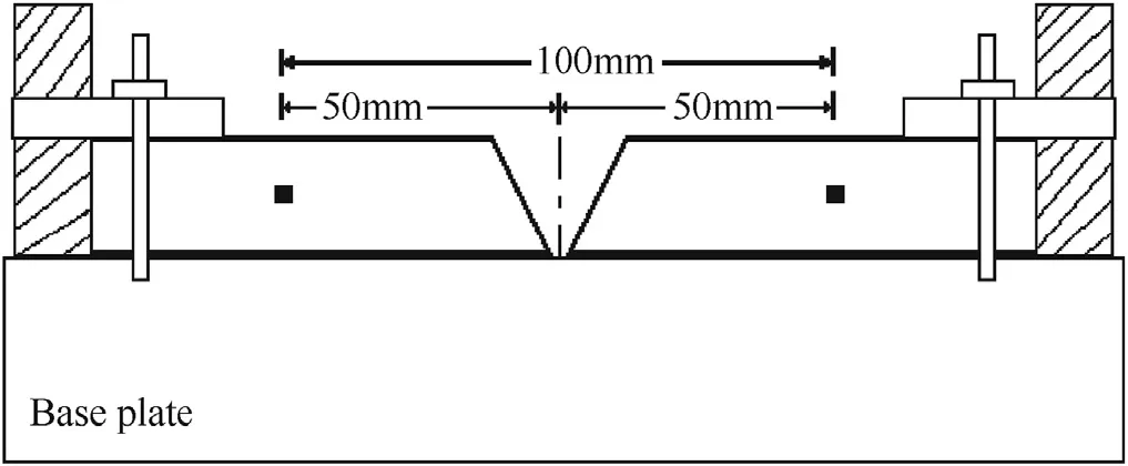
Fig. 1. Schematic diagram showing the technique of measurement of transverse shrinkage.
3. Results
The present section describes the advantage of DP-GMAW process over the P-GMAW process in welding of AISI 310S ASS in reference to the improved mechanical and metallurgical properties of the weld joint.
3.1. Macrograph of weld joint
The typical macrographs of the weld as revealed in a transverse section of P-GMAW and DP-GMAW joints are shown in Fig. 2(a) and (b), respectively which depicts the typical multi-pass deposition and desired sidewall fusion with respect to the absence of defect. In addition, it is also observed that the weld pool size per pass by DP-GMAW shows relatively smaller than that by P-GMAW. This may be considered as the advantage of DP-GMAW in reference to the reduction in stress generation of the weld joint.
3.2. Transverse shrinkage of weld joint
The effects of P-GMAW and DP-GMAW processes on transverse shrinkage of weld joint observed during welding are shown in Table 3. It can be seen from Table 3 that DP-GMAW process instead of P-GMAW process is used to minimize the transverse shrinkage of weld joint by 40% during welding.
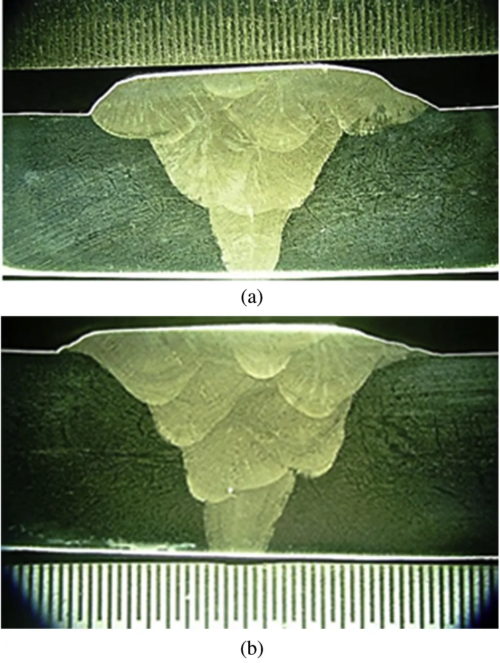
Fig. 2. Typical macrographs of weld joints. (a) P-GMAW and (b) DP-GMAW.

Table 3Effects of welding processes on transverse shrinkage generated in weld joint.
3.3. Microstructures of weld and HAZ
The microstructure of the multi-pass P-GMAW weld deposit has been found to consist of a mixture of dendrite and fine grain reheat-refined regions in the matrix, as shown in Fig. 3. This may happen due to partial heat treatment of matrix by multi-pass deposition. The typical morphology of dendrite observed in the central part of the weld is shown in Fig. 4. It is observed that the cast structure of P-GMAW deposit is found to be finer primarily due to the variation in thermal shock during solidification through interruption in metal deposition imparted by the pulsed current. However, it is further observed that the microstructure of the weld consists of a primary dendritic phase (brighter area) and secondary inter-dendritic phase (darker area) that is formed during the terminal stage of solidification.
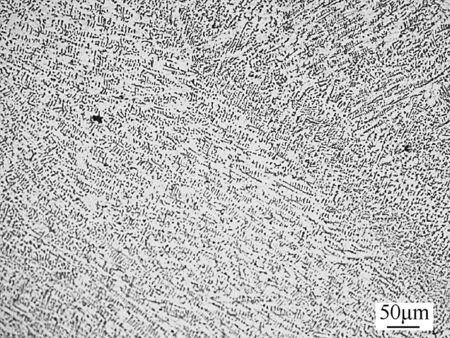
Fig. 3. Typical microstructure of multi-pass P-GMA weld deposition.
The typical microstructure of the heat affected zone (HAZ) of the weld joint prepared using P-GMAW process is shown in Fig. 5. The microstructure of HAZ adjacent to the fusion lineof the P-GMAW weld shows a certain extent of grain coarsening near to fusion line. This may happen primarily due to the considerable effect of weld isotherm arising out of the heat of weld deposition adjacent to the groove wall.
From Fig. 5, it is further analyzed that the inter-granular attack with respect to grain boundary thickening in HAZ away from the fusion line (0.5 mm) is present in the case of PGMA weld joint. The measured value of thickness is around 5±2 μm which is lesser than those of conventional ASS weld joints reported by Ghosh et al. [12].
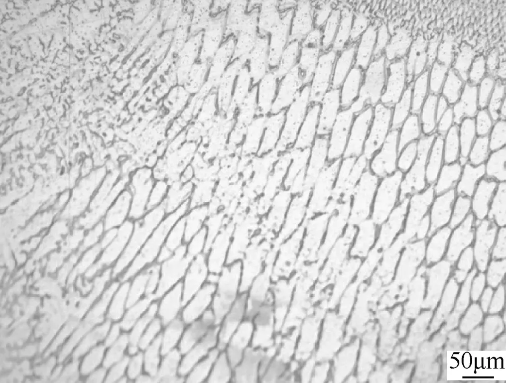
Fig. 5. Typical microstructure of HAZ near to fusion line in P-GMA weld.
The typical microstructure of the multi-pass DP-GMAW deposit is shown in Fig. 6. As in the case of P-GMAW deposit (Fig. 3) here also it is found to consist of a mixture of dendrite and fine grain reheat-refined regions in the matrix. However, the morphology of DP-GMAW weld is different from that of P-GMAW multi-pass weld deposit. The DP-GMAW deposit primarily shows a considerable refinement of microstructure along with scarcely distributed dendritic structure, whereas the P-GMAW weld (Fig. 3) shows the conventional pulsed behavior of multi-pass weld that significantly consists of both dendritic and reheat refined regions. Such variation of microstructure in DP-GMAW welds is primarily due to the variation in thermal shock during solidification through interruption in metal deposition imparted by the high frequency pulse current and low frequency thermal pulsation along with the usual reheat refinement by the subsequent weld pass. Thus, it is inferred that the use of DP-GMAW significantly reduces the dendritic region in the weld with respect to that observed in P-GMAW.
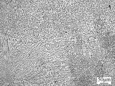
Fig. 6. Typical microstructure of multi-pass DP-GMA weld deposition.
The typical morphology of dendrite observed in central part of the weld deposit produced by DP-GMAW process is shown in Fig. 7. From Fig. 4, here also it is observed that the cast structure of DP-GMAW deposit is found to be finer primarily due to the combined effect of pulse current and thermal pulsation. However, it is further noticed that, because of thermal pulsation, the cast structure of DP-GMAW deposit is finer than that of the P-GMAW deposit.
The typical microstructure of the HAZ of the weld joint prepared using DP-GMAW process is shown in Fig. 8. Themicrostructure of HAZ adjacent to the fusion line of the DPGMAW weld shows a certain extent of grain coarsening. However, it is observed that DP-GMAW joint has comparatively less grain coarsening compared to P-GMA weld joint. This is due to thermal pulsation by DP-GMAW process as explained earlier.
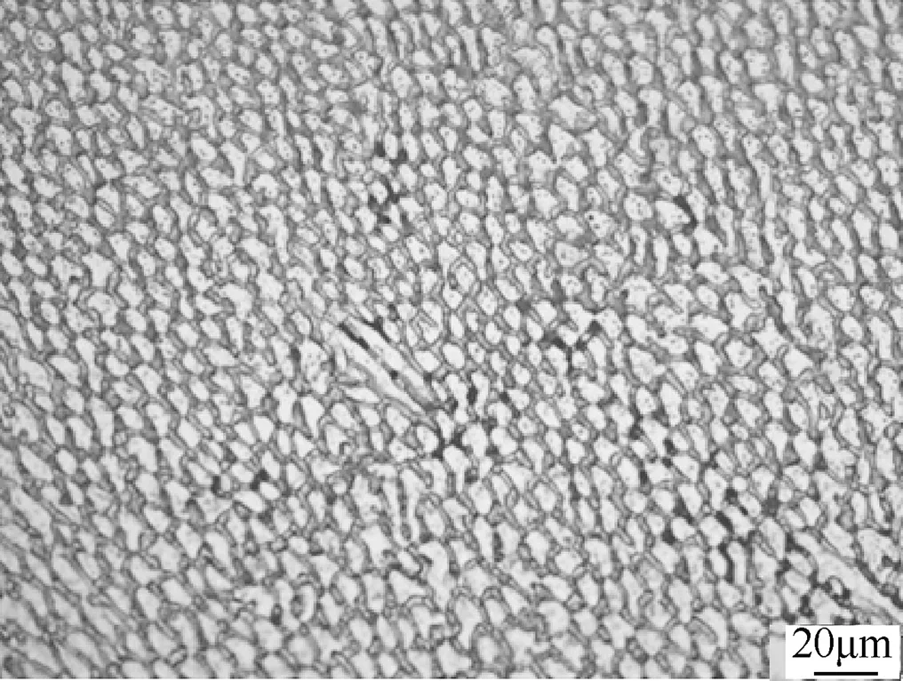
Fig. 7. Typical microstructure showing morphology of dendrite in DP-GMA weld.
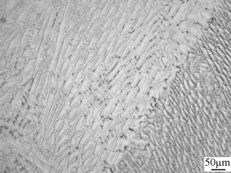
Fig. 8. Typical microstructure of HAZ near to the fusion line in DP-GMAW.
As in the case of P-GMA weldment, here also the intergranular attack with respect to grain boundary thickening in HAZ away from the fusion line (0.5 mm) of DP-GMAW joint was analyzed. The grain boundary thickening is not clearly visible from Fig. 8. Thus, it is understood that the severity of weld thermal cycle produced by DP-GMAW process is less due to dual pulse effect caused by superimposition of thermal pulse in comparison to that of the P-GMAW process.
3.4. Mechanical properties
The transverse tensile test of the weld joints prepared by PGMAW and DP-GMAW procedure is given in Table 4. The Cv-impact toughness and hardness of weld metal are also given in Table 4. It is observed that the mechanical properties of DP-GMA weld joint is higher than those of P-GMA weld joint due to thermal pulsation.

Table 4Mechanical properties of P-GMAW and DP-GMAW joints.
4. Discussion
In view of the results discussed above, it is clearly understood that the DP-GMAW process is used to improve the mechanical and metallurgical properties and minimize the transverse shrinkage of AISI: 310 ASS weld joints in comparison to the P-GMAW process. Further, it is noticed that, in the case of AISI: 310S ASS weld joint prepared by DP-GMAW process, the severity of inter-granular attack in the grain boundary of HAZ region of the weld joint is reduced. Such an improved property obtained by using DPGMAW is largely due to the combined effect of pulsed current and thermal pulsation of the process. The thermal pulsation effect primarily obtained in the DP-GMAW by varying wire feed rate (WFR) is shown in Fig. 9. It is observed that DP-GMAW shows the variation of WFR from the given WFR setting in the power source, but such variation is not observed in P-GMAW process. The variation ofWFR in DP-GMAW is to maintain a constant arc length because there is a chance to vary the arc length at a given WFR during the thermal pulsation period. This behavior reflects in the current and voltage waveforms (Figs. 10 and 11). The variation of WFR also confirms the synchronization between high frequency pulse and thermal pulse. This synchronization of pulses stirs the weld pool, reduces the heat input of DP-GMAW process accordingly and improves the properties of weld joints.

Fig. 9. Comparison of WFR between actual and variation observed during DPGMAW.
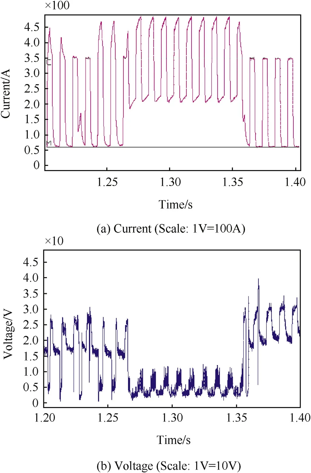
Fig. 10. At a given WFR of 4 m/min, typical waveform of DP-GMAW process.
In order to confirm the variation of WFR during DPGMAW under dynamic operating conditions, the waveforms of welding current and arc voltage were studied. The typical current and voltage waveforms at relatively low and high WFR of 4 and 9 m/min during DP-GMAW are shown in Figs. 10 and 11, respectively. From the figures it is observed that the arc voltage decreases during the thermal pulsation period, but the welding current increases due to the variation of WFR. These behaviors indicate that the DP-GMAW process introduces comparatively more thermal shock in the weld pool in comparison to the P-GMAW process. This is a beneficial effect to improve the characteristics of weld joints.
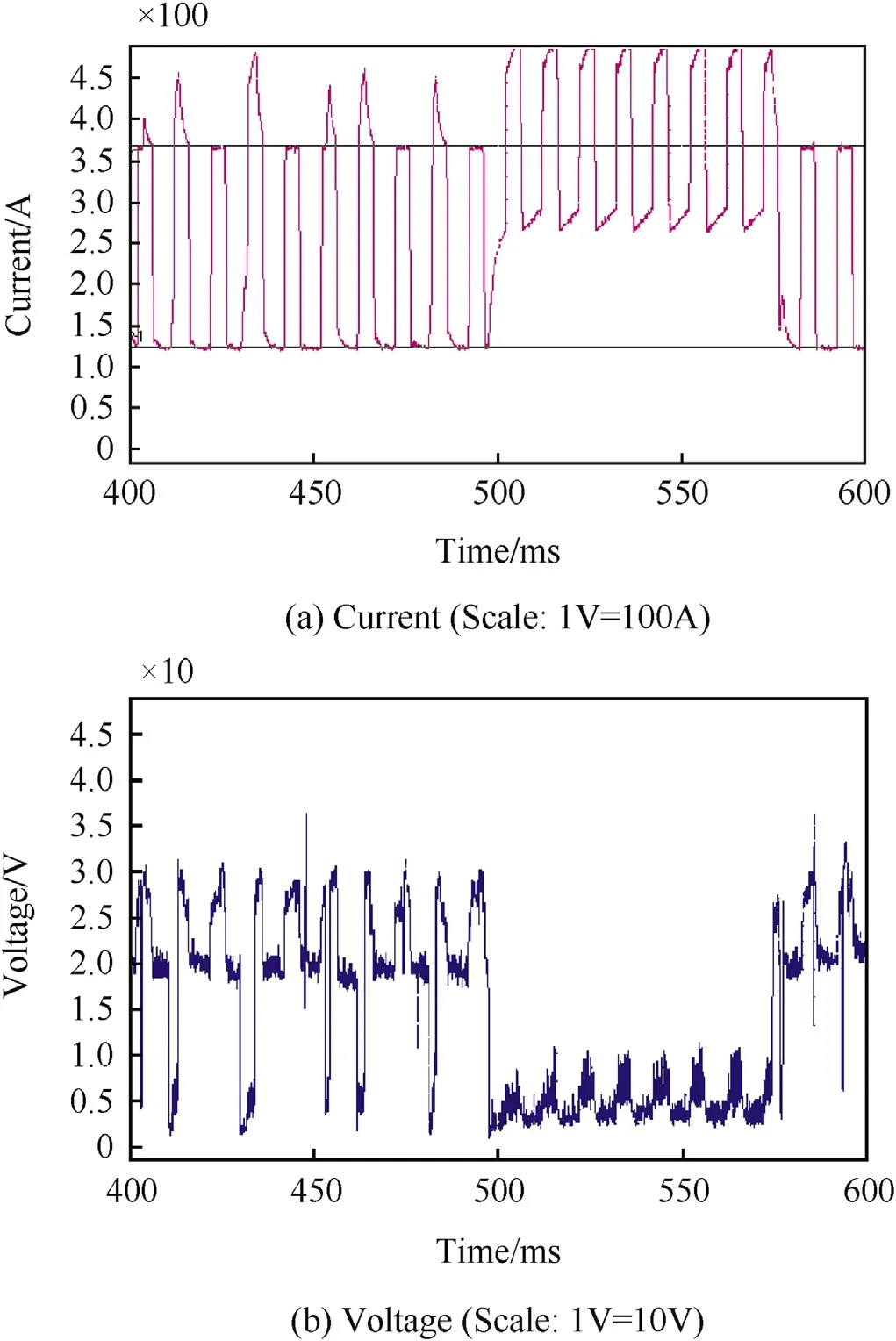
Fig. 11. At a given WFR of 9 m/min, typical waveform of DP-GMAW process.
5. Conclusions
This study highlights the superiority of DP-GMAW in place of P-GMAW in welding of grade AISI: 310S ASS material. Some of the key observations of the study are as follows.
1) The transverse shrinkage of AISI: 310S ASS weld joints prepared by DP-GMAW process is comparatively lower than that prepared by P-GMAW process.
2) The DP-GMAW process improves the mechanical and
metallurgical properties of AISI: 310S ASS weld joints. 3) In the case of AISI: 310S ASS, the use of the DP-GMAW
process reduces the susceptibility of inter-granular attack in HAZ.
4) Superior weld joint properties obtained by DP-GMAW process is primarily due to the fluctuation of WFR during the thermal pulsation period, which reduces the overall heat input and improves the properties of the weld joints accordingly.
Acknowledgment
The authors thankfully acknowledge the Welding Research Institute (WRI) Trichy, for carrying out welding trials.
References
[1] Welding brazing and solderingASM handbook, vol. 6. Materials Park, OH: ASM International; 2010.
[2] Cuiuri D, Norrish J, Cook CD. New approaches to controlling unstable gas metal arc welding. Australas Weld 2002;47(3):39—47.
[3] Norrish John. Process modification in gas metal arc welding for enhanced performance. Aust Weld J 2013;58:33—8.
[4] Praveen P, Yarlagadda PKDV, Kang MJ. Advancements in pulse gas metal arc welding. J Mater Process Technol 2005;164:1113—9.
[5] Liu Anhua, Tang Xinhua, Lu Fenggui. Study on welding process and prosperities of AA5754 Al-alloy welded by double pulsed gas metal arc welding. Mater Des 2013;50:149—55.
[6] Mendes da Silva Celina Leal, Scotti Americo. The influence of double pulse on porosity formation in aluminum GMAW. J Mater Process Technol 2006;171:366—72.
[7] Devakumaran K, Rajasekaran N, Ghosh PK. Process characteristics of inverter type GMAW power source under static and dynamic operating conditions. Mater Manuf Process 2012;27(12):1450—6.
[8] Tavares SSM, Moura V, da Costa VC, Ferreira MLR, Pardal JM. Microstructural changes and corrosion resistance of AISI 310S steel exposed to 600—800°C. Mater Charact 2009;60:573—8.
[9] Shah Hosseini H, Shamanian M, Kermanpur A. Characterization of microstructures and mechanical properties of Inconel 617/310 stainless steel dissimilar welds. Mater Charact 2011;62:425—31.
[10] Naffakh H, Shamanian M, Ashrafizadeh F. Dissimilar welding of AISI 310 austenitic stainless steel to nickel-based alloy Inconel 657. J Mater Process Technol 2009;209:3628—39.
[11] Kimura M, Ichihara A, Kusaka M, Kaizu K. Joint properties and their improvement of AISI 310S austenitic stainless steel thin walled circular pipe friction welded joint. Mater Des 2012;38:38—46.
[12] Ghosh PK, Kulkarni SG, Kumar M, Dhiman HK. Pulsed current GMAW for superior weld quality of austenitic stainless steel sheet. ISIJ Int 2007;47(1):138—45.
* Corresponding author. Tel.: +91 9443689943.
- Defence Technology的其它文章
- Effect of welding processes on mechanical and microstructural characteristics of high strength low alloy naval grade steel joints S. RAGU NATHANa,*, V. BALASUBRAMANIANb,1, S. MALARVIZHIb,2, A.G. RAOc,3
- Pitting corrosion resistance and bond strength of stainless steel overlay by friction surfacing on high strength low alloy steel Amit Kumar SINGHa,*, G. Madhusudhan REDDYa, K. Srinivas RAOb
- Friction welding of AA6061 to AISI 4340 using silver interlayer SURESH D. MESHRAM*, G. MADHUSUDHAN REDDY
- Stress corrosion cracking behaviour of gas tungsten arc welded super austenitic stainless steel joints M. VINOTH KUMARa,*, V. BALASUBRAMANIANb,1, S. RAJAKUMARb, SHAJU K. ALBERTc
- Influence of process parameters on physical dimensions of AA6063 aluminium alloy coating on mild steel in friction surfacing B. VIJAYA KUMARa,*, G. MADHUSUDHAN REDDYb, T. MOHANDASc
- Comparative study on transverse shrinkage, mechanical and metallurgical properties of AA2219 aluminium weld joints prepared by gas tungsten arc and gas metal arc welding processes S. ARUNKUMARa, P. RANGARAJANa, K. DEVAKUMARANb, P. SATHIYAa,*

