
Comparative study on transverse shrinkage, mechanical and metallurgical properties of AA2219 aluminium weld joints prepared by gas tungsten arc and gas metal arc welding processes S. ARUNKUMARa, P. RANGARAJANa, K. DEVAKUMARANb, P. SATHIYAa,*
2015-07-02 06:14:13DeprtmentofProductionEngineeringNtionlInstituteofTechnologyTiruchirpplli620015TmilnduIndiWeldingReserchInstituteBHELTiruchirpplliTmilnduIndiReceived29April2015revised18My2015ccepted27My2015Avilleonline25June2015
Defence Technology 2015年3期
Deprtment of Production Engineering, Ntionl Institute of Technology, Tiruchirpplli 620015, Tmilndu, IndiWelding Reserch Institute, BHEL, Tiruchirpplli, Tmilndu, IndiReceived 29 April 2015; revised 18 My 2015; ccepted 27 My 2015 Aville online 25 June 2015
Comparative study on transverse shrinkage, mechanical and metallurgical properties of AA2219 aluminium weld joints prepared by gas tungsten arc and gas metal arc welding processes S. ARUNKUMARa, P. RANGARAJANa, K. DEVAKUMARANb, P. SATHIYAa,*
aDepartment of Production Engineering, National Institute of Technology, Tiruchirappalli 620015, Tamilnadu, IndiabWelding Research Institute, BHEL, Tiruchirappalli, Tamilnadu, India
Received 29 April 2015; revised 18 May 2015; accepted 27 May 2015 Available online 25 June 2015
Abstract
Aluminium alloy AA2219 is a high strength alloy belonging to 2000 series. It has been widely used for aerospace applications, especially for construction of cryogenic fuel tank. However, arc welding of AA2219 material is very critical. The major problems that arise in arc welding of AA2219 are the adverse development of residual stresses and the re-distribution as well as dissolution of copper rich phase in the weld joint. These effects increase with increase in heat input. Thus, special attention was taken to especially thick section welding of AA2219-T87 aluminium alloy. Hence, the present work describes the 25 mm-thick AA2219-T87 aluminium alloy plate butt welded by GTAW and GMAW processes using multi-pass welding procedure in double V groove design. The transverse shrinkage, conventional mechanical and metallurgical properties of both the locations on weld joints were studied. It is observed that the fair copper rich cellular (CRC) network is on Side-A of both the weldments. Further, it is noticed that, the severity of weld thermal cycle near to the fusion line of HAZ is reduced due to low heat input in GTAW process which results in non dissolution of copper rich phase. Based on the mechanical and metallurgical properties it is inferred that GTAW process is used to improve the aforementioned characteristics of weld joints in comparison to GMAW process.
Copyright©2015, China Ordnance Society. Production and hosting by Elsevier B.V. All rights reserved.
Keywords:AA2219; Transverse shrinkage; Microstructure
E-mail address: psathiya@nitt.edu (P. SATHIYA).
Peer review under responsibility of China Ordnance Society.
http://dx.doi.org/10.1016/j.dt.2015.05.008
2214-9147/Copyright©2015, China Ordnance Society. Production and hosting by Elsevier B.V. All rights reserved.
1. Introduction
AA2219 is basically Al—Cu—Mn ternary alloy and has a unique combination of properties such as good weldability and high strength to weight ratio [1]. The alloy is extensively used for fabrication of cryogenic tanks and pressure vessels due to high strength, superior resistance to cracking and corrosion resistance [1]. The AA2219 aluminium alloy contains a major alloying addition of copper and minor additions of manganese, titanium, vanadium and zirconium. Generally, the alloy is producedintheT87tempercondition(solution treatment + 7% cold working + aging) [2]. One of the drawbacks of most of the high strength Al alloys is that they suffer from poor weldability. However, AA2219 is an exception due to the presence of more Cu that helps in healing the cracks by providing extra eutectics. Lots of studies have been carried out in order to assess the effect of copper content and the distribution of second phase intermetallic particles on the properties of AA 2219 alloy [3].
The preferred welding processes for AA 2219 aluminum alloy are frequently gas metal arc welding (GMAW) and gas tungsten arc welding (GTAW) due to their comparatively easier applicability and better economy. The gas tungsten arc welding (GTAW) process for aluminium alloy AA2319 asfiller metal has generally been used [4]. Although the AA2219 alloy has better weldability compared to other grades of precipitation hardenable aluminium alloy, it has inferior weld joint strength than base material [5]. It is well known that the weld strength of the alloy is characterized by the weldment microstructure, which largely depends on the welding processes. Several researchers have investigated the weld strength of the alloy and have confirmed that it has low weld strength after welding [6—8].
However, it is reported that the electron beam welding (EBW) provides strong and sound welds for AA2219 with high weld efficiency [1,9]. But, the application of EBW is practically difficult for certain weld joints. The observation of the high weld efficiency of the EBW process indicates the possibility of improving weld property through an appropriate process design using gas tungsten arc welding (GTAW) and gas metal arc welding (GMAW) processes and their comparisons have not been studied in detail. In addition, thick section by multi-pass arc welding procedure may generate high shrinkage stresses due to differential contraction under cooling thermal cycle of the welding process. Thus, it needs to study the various properties of the AA2219 weld joints under different welding processes. Hence, the present work describes the comparative studies on transverse shrinkage, mechanical and metallurgical properties of 25 mm-thick AA2219-T87 aluminium alloy weld joints prepared by GTAW and GMAW processes.
2. Experimental
2.1. Welding
25 mm-thick AA2219 plates were butt-welded by GTAW and GMAW processes. The plates were rigidly fixed to avoid distortion during welding. The welding parameters used for the present investigation are given in Table 1. Double V groove design was used, as shown in Fig. 1. The welding was carried out in automatic mode. The photographic view of the experimental setup is shown in Fig. 2. During welding the welding parameters, such as arc voltage and welding current, were measured using a digital meter fitted in the welding power source. Prior to the welding the plates were cleaned with brush followed by acetone to remove oxide layers and any faying surfaces. In the double V-groove, initially, welding was carried out on Side-B followed by Side-A (Fig. 1).
2.2. Measurement of transverse shrinkage
During welding the transverse shrinkage (Δtr) was measured with a given straining length (Ltr) of 60 mm. Change of straining length for each weld layer was measured using digital Vernier caliper with least count of 0.001 mm. The transverse shrinkage was measured in Side-A of double V weld groove (Fig. 1). The schematic diagram of transverse shrinkage measurement is shown in Fig. 3.
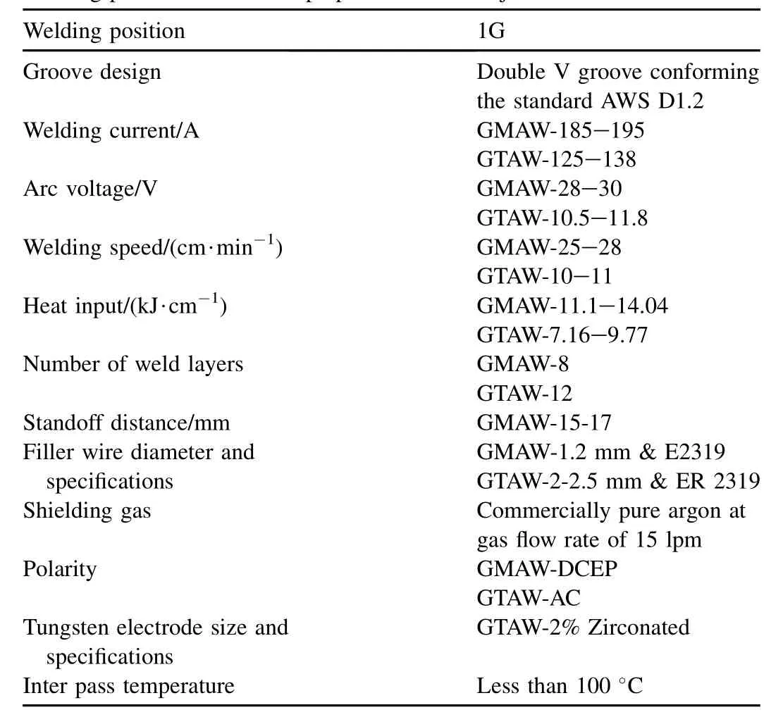
Table 1Welding parameters used for preparation of weld joints.
2.3. Studies on weld joint characteristics
After welding, the samples were extracted for various mechanical and metallurgical tests as per the AWS D1.2 standard. A metallography sample was prepared as per thestandard metallographic technique and etched with Weck's reagent (100 mL of water, 4 g of KMnO4and 1 g of NaOH). The scanning electron microscope (SEM) was used to characterize the various features of microstructures of weld joints. The tensile and hardness across the weldment were test as per the ASTM E8M and ASTM E370 standards, respectively. The tensile and hardness tests were carried out at both the locations of weld groove (Fig. 1). After tensile testing, the fractographs of the tensile tested samples were obtained by SEM.
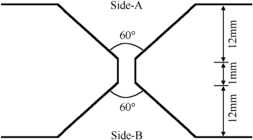
Fig. 1. Schematic diagram of Side-A and Side-B of double V groove.
Fig. 2. Photographic view of experimental setup.

Fig. 3. Schematic diagram of measurement of transverse shrinkage.
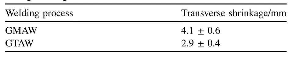
Table 2Effects of welding processes on transverse shrinkage generated during welding.
3. Results and discussion
3.1. Study on base metal
Typical microstructure of base metal is shown in Fig. 4. It is observed from Fig. 4 that the copper rich phase is distributed in the aluminium matrix. The copper rich phase significantly contributes to the increase in ultimate tensile strength (UTS) of around 402 MPa and the reduction in ductility of around 8% in AA2219 aluminium alloy.
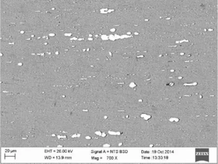
Fig. 4. Base metal microstructure.
3.2. Studies on weld joints
3.2.1. Transverse shrinkage
Effects of welding processes (GTAW and GMAW) on measured transverse shrinkage generated during welding are given in Table 2. The shrinkage occurs during welding due to differential cooling followed by localized application of heating. It is well known that the GTAW process generates low heat input to the work piece than GMAW process. Therefore the use of GTAW process minimizes the transverse shrinkage of around 30% in comparison to that of GMAW process.
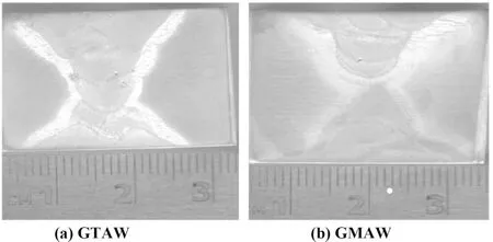
Fig. 5. Typical macrostructures of joints.
3.2.2. Metallography
Typical macrographs of transverse sections of weld joints of GMAW and GTAW processes are shown in Fig. 5. It is observed that the macrographs are significantly different from each other due to variation of amount of metal deposition per pass in each welding process.
Typical changes in microstructures of GMAW and GTAW deposits are shown in Fig. 6 (a) and (b) and Fig. 7 (a) and (b). The microstructures reveal the presence of dendrite and reheat refined regions in the multi-pass weld deposition. Minor variations in microstructure of the multi-pass welds in Side-A and Side-B were observed. However in comparison with GMAW welds, the GTAW welds show finer dendritic microstructure due to low heat input. The light areas represent copper and the dark areas represent aluminium. From Fig. 6 (a) and (b) and Fig. 7 (a) and (b), it is also observed that the partial copper rich cellular (CRC) network is in both the welds for multi-pass welding. However, the Side-A of both the welds shows a fair CRC network. The weld structure contributes to the improvements in yield strength through the absence of aligned CRC networks [10]. The distributed copper rich particles probably act to strengthen the matrix of the weld. The EDS analysis of the weld also indicates the presence of CuAl2phase in an aluminium matrix (Fig. 9 and Table 2). Similar observations in the case of electron beam welding of AA2219 aluminium alloy were reported by Gupta et al. [10].
Typical microstructures of HAZs of both the weldments near fusion line are shown in Fig. 8. It is observed that the copper rich phase (CRP) is not dissolved by using GTAW process due to low thermal impact, however such a distributed CRP is not observed in GMAW weldment.
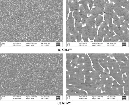
Fig. 6. Typical microstructures of weld deposits on Side-A of joints.
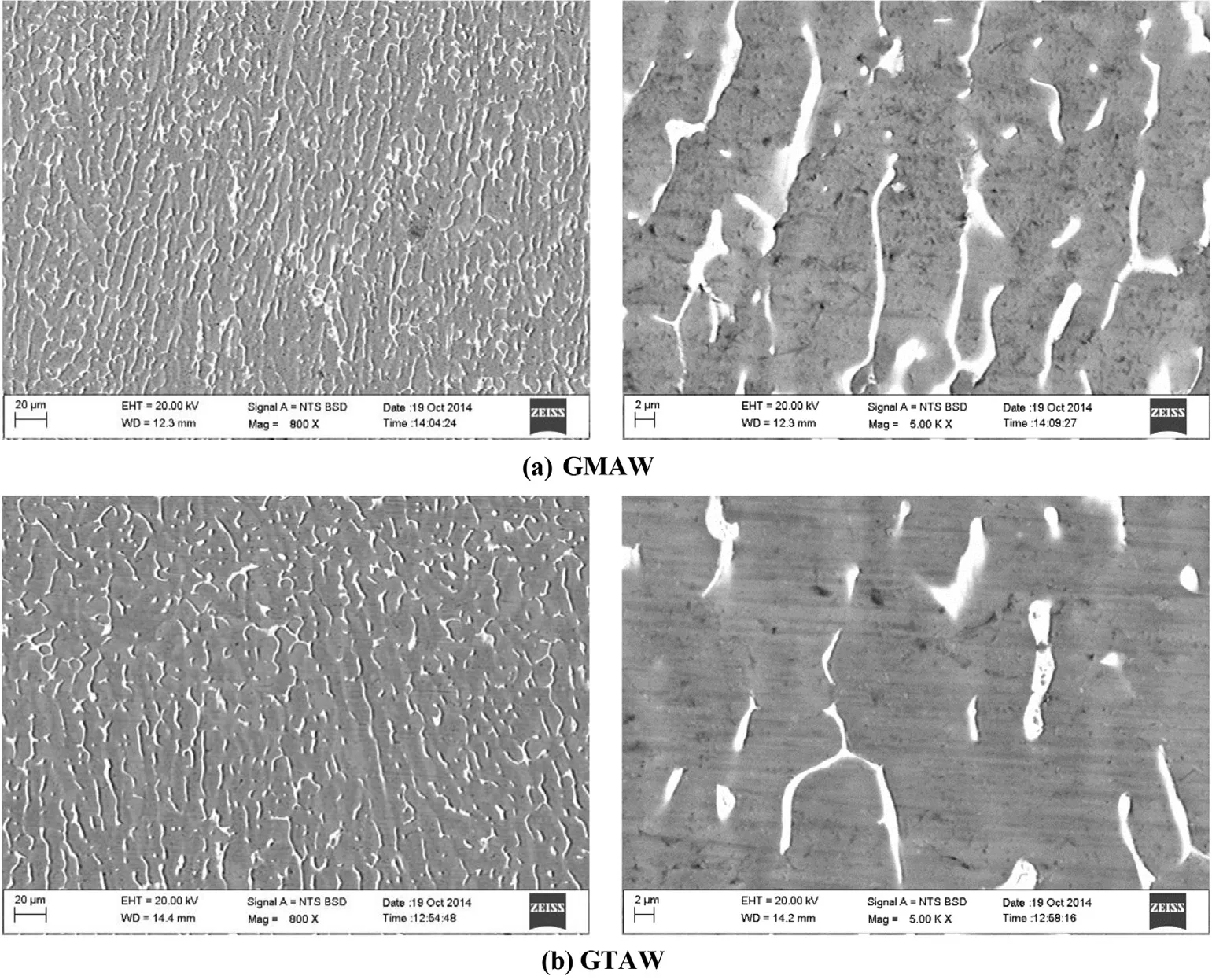
Fig. 7. Typical microstructures of weld deposits on Side-B of joints.
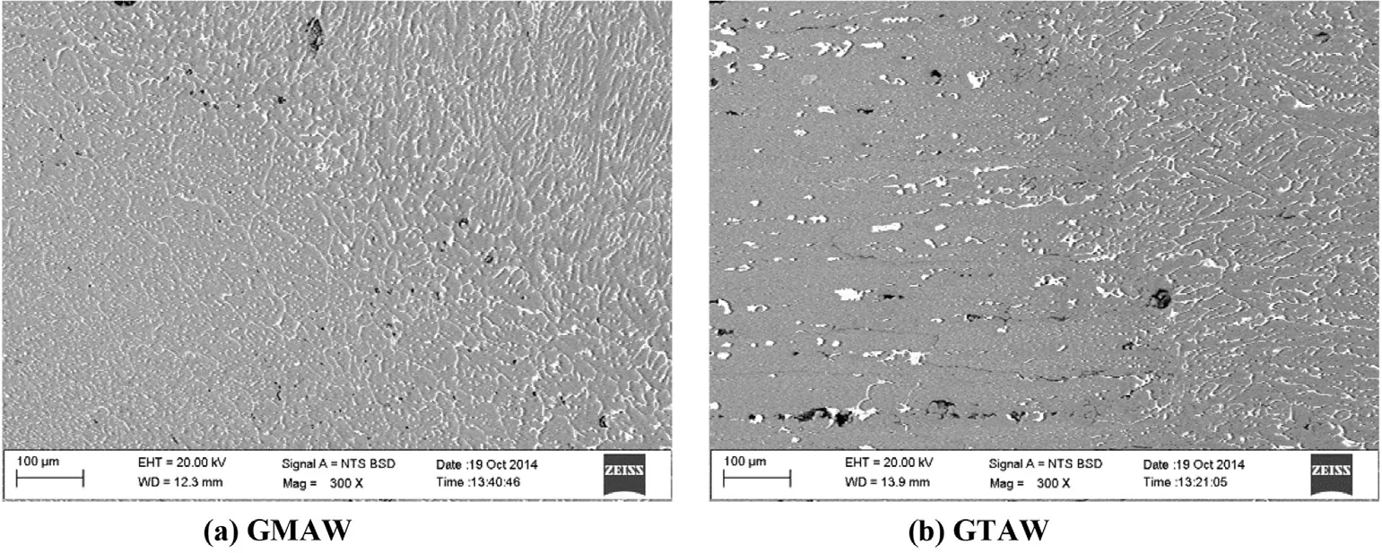
Fig. 8. Typical microstructures of HAZs near to fusion lines of weldments.
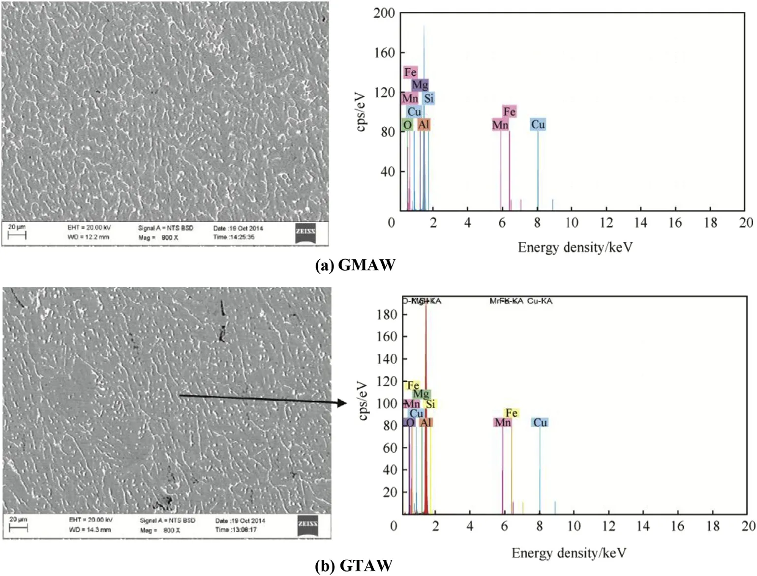
Fig. 9. EDS results of AA2219 weldments.
The chemical composition of the weld deposits are presented in Table 3.
Fig. 10 shows the XRD patterns of GTAW and GMAW welds. It is clearly shows that all the peaks are corresponding to the Al and small amount of intermetallic compounds like Al2Cu is observed through the XRD pattern.
Table 3Chemical composition of weld deposits.

Fig. 10. XRD analysis of weld metal (GTAW and GMAW).
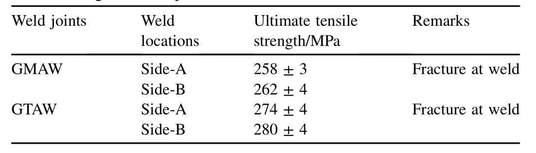
Table 4Tensile strength of weld joints.
3.3. Mechanical properties
Effects of welding processes (GMAW and GTAW) on ultimate tensile strengths (UTSs) of both Side-A and Side-B of weld joints are given in Table 4. It is observed that UTS of GTAW weld joint is superior compared to that of GMAW weld joint. The UTS is increased by around 11%. The improved property achieved in GTAW process is primarily due to finer dendritic microstructure in the weld deposit as explained earlier. However, from the fractures of weld joints occurred at the weld it can be seen that the weld joint has inferior UTS compared to base metal (around 405 MPa). Typical fractographs of tensile tested samples are shown in Fig. 11. It is observed that comparatively GTAW weld resulted in finer dimples due to the presence of finer dendritic structure than GMAW weld.
Hardness distribution across the weld joints under different locations of double V-groove is in Fig. 12. It is observed that the hardness value for both the weld deposits are lower than those of base metal and heat affected zone irrespective of change in weld locations due to cast structure. In addition, the precipitation hardening may also contribute to higher hardness in HAZ. However, it is interesting to notice that, because of low heat input in GTAW process, HAZ of GTAW process shown relatively low hardness value with GMAW's HAZ on both the locations.
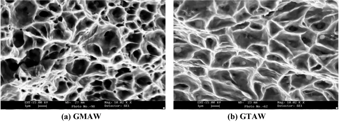
Fig. 11. SEM fractograph of tensile tested samples.
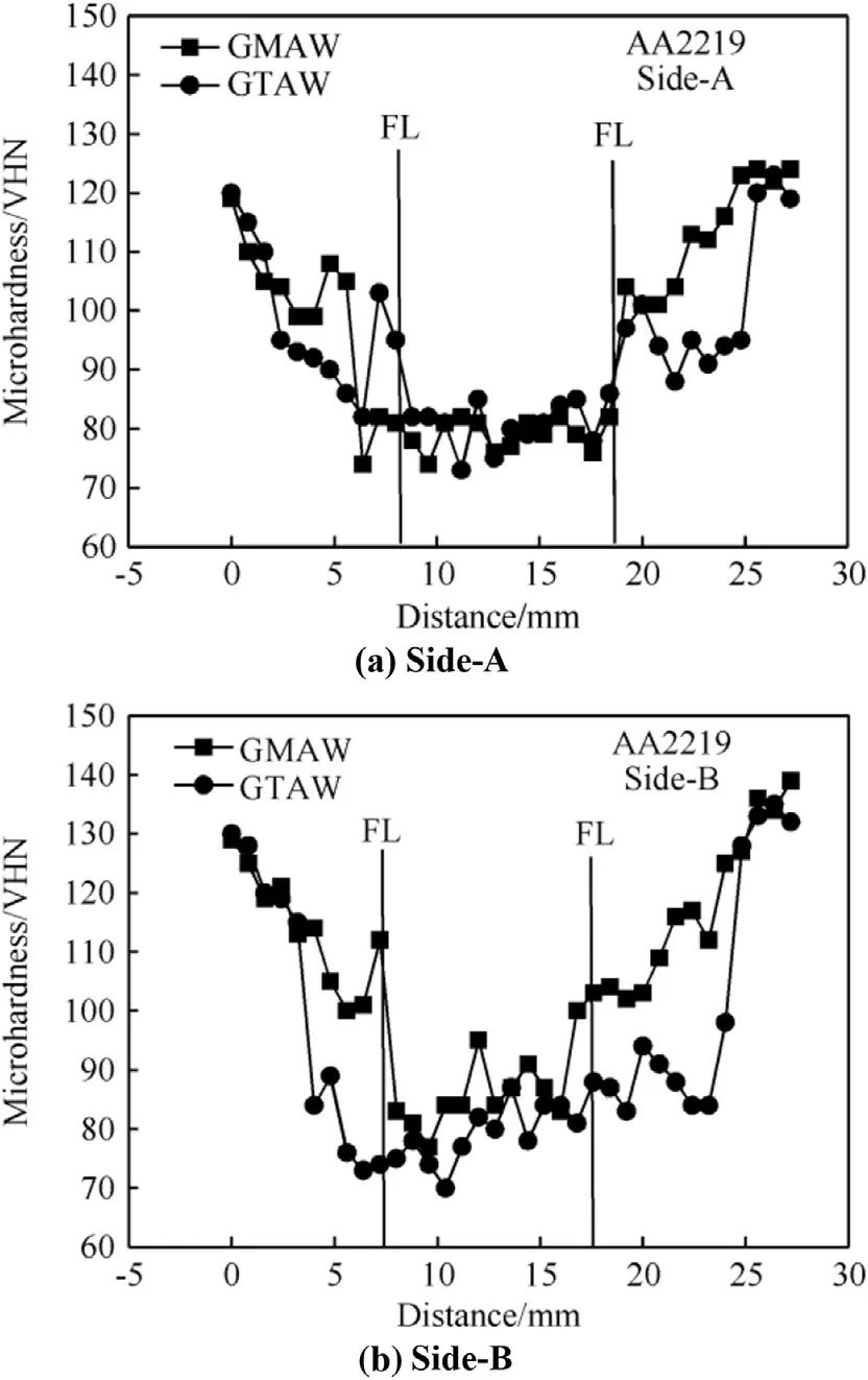
Fig. 12. Hardness distribution across the transverse section of weld joints.
4. Conclusions
The following conclusions are drawn from the present investigation:
1) The transverse shrinkage generated in GTAW weld joint is comparatively lower than that in GMAW weld joint.
2) From the EDS analysis, it is concluded that the use of GTAW process reduces the severity of weld thermal cycle in weld deposit and HAZ region.
3) The tensile strength of GTAW weld joint is higher than that of the GMAW weld joint.
4) The hardness's of GTAWand GMAW welds are lesser than those of the base metal and heat affected zone.
5) X-ray Diffraction patterns revealed that Al is the major phases, and small amount of Al2Cu was observed.
6) From SEM fractograph, the finer dimples were observed in GTAW tensile fractured sample.
Acknowledgement
We acknowledge Shri P.Sankaravelayutham, Dy. General Manager, MMD/MME, VSSC, ISRO, Thiruvanandhapuram-695022 to provide the base material and WRI, BHEL, Trichy, Tamilnadu to carry out the welding trials.
References
[1] Hartman JA, Beil RJ, Hahn GT. Effect of copper rich regions on tensile properties of VPPA weldments of 2219-T87 aluminium. Weld J 1987;66:73s—83s.
[2] Nair Biju S, Rakesh S, Phanikumar G, Prasad Rao K, Sinha PP. Fracture toughness (J1C) of electron beam welded AA2219 alloy. Mater Des 2010;31(10):4943—50.
[3] Venkatasubramanian G, Sheik Mideen A, Jha Abhay K. Corrosion behavior of aluminium alloy Aa2219-T87 welded plates in sea water. Indian J Sci Technol 2012;5(11):3578—83.
[4] Ghosh BR, Gupta RK, Biju S, Sinha PP. Modified welding technique of hypo-eutectic Al—Cu alloy for higher mechanical properties. Solid Mech Mater Eng 2007;1(4):469—79.
[5] Dance GI. Comparative evaluation of mechanical properties of TIG, MIG, EBW and VPPA welded AA2219 aluminium alloy. Weld Metal Fabr 1994;24:216—22.
[6] Srinivasan PB, Arora KS, Dietzel W, Pandey S, Schaper MK. Characterization of microstructure, mechanical properties and corrosion behaviour of anAA2219frictionstir weldment. J AlloysCompd 2010;492(1):631—7.
[7] Koteswara Rao SR, Madhusudhana Reddy G, Srinivasa RK, Kamaraj M, Prasad Rao K. Reasons for superior mechanical and corrosion properties of 2219 aluminiumalloy electron beam welds. Mater Charact 2006;40(4—5):236—48.
[8] Malarvizhi S, Raghukandan K, Viswanathan N. Effect of post weld aging treatment on tensile properties of electron beam welded AA2219 aluminium alloy. Int J Adv Manuf Technol 2008;37(3):294—301.
[9] Robinson IB, Collins FR, Dowd JD. Welding high strength aluminium alloys. Weld J 1962;42:221s—8s.
[10] Gupta RK, Ghosh BR, Biju S, Sinha PP. GTAW process design for improvedweldstrengthof AA2219. J Australas WeldJ 2009;54:37—48.
* Corresponding author. Tel.: +91 431 2503510; fax: +91 431 2500133.
- Defence Technology的其它文章
- Effect of welding processes on mechanical and microstructural characteristics of high strength low alloy naval grade steel joints S. RAGU NATHANa,*, V. BALASUBRAMANIANb,1, S. MALARVIZHIb,2, A.G. RAOc,3
- Pitting corrosion resistance and bond strength of stainless steel overlay by friction surfacing on high strength low alloy steel Amit Kumar SINGHa,*, G. Madhusudhan REDDYa, K. Srinivas RAOb
- Friction welding of AA6061 to AISI 4340 using silver interlayer SURESH D. MESHRAM*, G. MADHUSUDHAN REDDY
- Stress corrosion cracking behaviour of gas tungsten arc welded super austenitic stainless steel joints M. VINOTH KUMARa,*, V. BALASUBRAMANIANb,1, S. RAJAKUMARb, SHAJU K. ALBERTc
- Influence of process parameters on physical dimensions of AA6063 aluminium alloy coating on mild steel in friction surfacing B. VIJAYA KUMARa,*, G. MADHUSUDHAN REDDYb, T. MOHANDASc
- Pulsed current and dual pulse gas metal arc welding of grade AISI: 310S austenitic stainless steel A. MATHIVANANa, A. SENTHILKUMARb, K. DEVAKUMARANc,*