Gas tungsten arc welding of ZrB2
—SiC based ultra high temperature ceramic composites R.V. KRISHNARAO*, G. MADHUSUDHAN REDDY
Defence Metallurgical Research Laboratory, Kanchanbagh, Hyderabad 500058, IndiaReceived 11 March 2015; revised 16 March 2015; accepted 17 March 2015 Available online 18 April 2015
Gas tungsten arc welding of ZrB2
—SiC based ultra high temperature ceramic composites R.V. KRISHNARAO*, G. MADHUSUDHAN REDDY
Defence Metallurgical Research Laboratory, Kanchanbagh, Hyderabad 500058, India
Received 11 March 2015; revised 16 March 2015; accepted 17 March 2015 Available online 18 April 2015
Abstract
The difficulty in fabricating the large size or complex shape limits the application of ZrB2—SiC composites. Joining them by fusion welding without or with preheating, controlled cooling under protective gas shield leads to thermal shock failure or porosity at the weld interface. In the present work, a filler material of (ZrB2—SiC—B4C—YAG) composite with oxidation resistance and thermal shock resistance was produced in the form of welding wire. Using the filler, gas tungsten arc welding (GTAW) was performed without employing preheating, post controlled cooling and extraneous protective gas shield to join hot pressed ZrB2—SiC (ZS), and pressureless sintered ZrB2—SiC—B4C—YAG (ZSBY) composites to themselves. The fusion welding resulted in cracking and non-uniform joining without any filler material. The weld interfaces of the composites were very clean and coherent. The Vickers micro-hardness across the weld interface was found to increase due to the increase in the volume % of both SiC and B4C in the filler material. The shear strength of the weld was about 50% of the flextural strength of the parent composite.
Copyright©2015, China Ordnance Society. Production and hosting by Elsevier B.V. All rights reserved.
Keywords:ZrB2; SiC; Composites; Welding; Filler; Shear strength
E-mail addresses: rvkr4534@yahoo.com(R.V. KRISHNARAO), gmreddy_dmrl@yahoo.co.in (G. MADHUSUDHAN REDDY).
Peer review under responsibility of China Ordnance Society.
http://dx.doi.org/10.1016/j.dt.2015.03.002
2214-9147/Copyright©2015, China Ordnance Society. Production and hosting by Elsevier B.V. All rights reserved.
1. Introduction
ZrB2is the leading material among ultra-high-temperature ceramics due to its high melting point (3245°C), high hardness (23 GPa), high thermal conductivity (~60 W m-1·k-1), electrical conductivity (~107S m-1), and relatively low density (6.09 g cm-3), high strength at elevated temperatures, and stability in extreme environments [1]. The addition of SiC and carbon can inhibit the grain growth, improve the sinterability, and increase the thermal and mechanical properties and oxidation resistance [2,3]. ZrB2—SiC based ceramics are attractive for aerospace applications such as thermal protection systems, leading edges, trailing edges, and propulsion components for hypersonic flight vehicles [4,5].
The components of ZrB2—SiC composite are generally made by pressureless sintering (PS) or hot pressing (HP). The difficulty in fabricating the large size or complex shapes limits the application of ZrB2—SiC composites. Joining is an alternative and cost effective method for fabricating the large size or complicated shape components of ceramics. Joining of engineering ceramics such as Al2O3, SiC, C/C, C/SiC has been widely studied [6—11]. Recently, several investigations on joining of ZrB2—SiC composites have been reported in the literature. Bellosi et al. [12] joined ZrB2—SiC composites using Ca—Al—Si—O, and Y—Al—Si—O glass powders as bonding inter layers at 1440°C and reported a bending strength of 277 MPa at room temperature. Among other reports, brazing is the most common method. Muolo et al. [13] studied the wetting behavior of ZrB2with different metals (Cu, Ag, Au) and their alloys and optimal results were obtained with silver-based alloys. Due to low melting point of these solders, the joints cannot be useful at temperature above 1000°C.
Singh et al. [14] studied the joining of ZrB2—SiC9—SiC, ZrB2—SiC—C and ZrB2—SiC to themselves and to commercially pure Ti using boron containing Ni base braze alloys (MBF-20 and MBF-30). Asthana et al. [15] studied the joining of similar composites to themselves using Pd-based brazes Palco (65% Pd-35% Co) and Palni (60% Pd-40% Ni). Hair line cracks, substantial chemical interaction and interfacial cracking due to residual stresses were observed.
Practical applications also require joining of ZrB2—SiC composites to refractory metals like Nb and its alloys. Bo et al. [16] joined the monolithic ZrB2and ZrB2—SiC composites to themselves using pure Ni powder. The maximum shear strengths of 59.7±5.3 MPa and 43.4±7.5 MPa were obtained for ZrB2and ZrB2—SiC joints, respectively. Peng et al. [17] diffusionally bonded ZrB2—SiC composites to Nb using Ti interlayer to synthesize TiB whiskers array insitu and reported a maximum shear strength of 158 MPa. Yang et al. [18] diffusionally bonded ZrB2—SiC to Nb using dynamically compressed Ni foam interlayer and reported a maximum shear strength of 155.6 MPa.
Though arc welding of ZrB2is possible due to its electrical conductivity [19], the research on joining by gas tungsten arc welding (GTAW) or plasma arc welding is very limited. Brown et al. [20] reported fusion welding of ZrB2-20 vol% SiC and ZrB2—SiC—B4C composites. By preheating and controlled cooling under protective atmosphere the 3 mmthick parts were joined by GTAW. The strength of joints was¼ of the strength of parent material. Thermal conductivity of joints was higher than that of parent material. Very recently King et al. [21] reported the plasma arc welding of TiB2—20 vol % TiC composites and ZrB2-20 vol % ZrC composites [22] achieved by preheating the weld coupons to 150°C.
In the present work, a filler material of (ZrB2—SiC—B4C—YAG) composite with oxidation resistance and thermal shock resistance has been produced in the form of welding rods. The filler was used in GTAW of HP (ZrB2—20 vol.% SiC), and PS (ZrB2—20 vol.% SiC—8 vol.% B4C—7 vol.% YAG) composites. Without any preheating, post controlled cooling, and extraneous protective gas shield, GTAW was performed manually.
2. Experiment
2.1. Materials
Powders of ZrB2and SiC with average particle sizes (d50~1.5—3 μm) and (d50~1.5 μm) respectively obtained from H. C. Strack, Germany and B4C powder of (d50~7 μm) supplied by Electro Abrasive Corporation, USA were used to fabricate ZrB2-20 vol.% SiC composite. For (ZrB2—SiC—B4C) composite with addition of YAG (Y2O3+ Al2O3), ZrB2was produced using ZrO2powder supplied by Nuclear Fuel Complex, Hyderabad, India and B4C powder supplied by China Abrasives, Zingzhou, China. SiC powder with particle size (d50~0.8 μm) was supplied by H.C. Starck, Germany. Al2O3with super fine size (d50~0.7 μm) obtained from Alcan and sub-micron sized Y2O3were used.
2.2. Hot-pressing
ZrB2-20 vol.% SiC composite was fabricated by hot pressing under vacuum. ZrB2-20 vol.% SiC with 1 wt% B4C powder was mixed in a polythene bottle with alumina balls for 24 h and then hot-pressed in graphite dies at 2000°C with a heating rate of 15°C/min and a uniaxial pressure of 25 MPa for 1 h. The bulk density, theoretical density and grain size of the composite (ZrB2-20 vol.% SiC-1 wt.% B4C) designated ZS are 5.43 g cm-3, 5.44 g cm-3and 4.02 μm, respectively.
2.3. Pressureless sintering
(ZrB2—SiC—B4C) composite was pressurelessly sintered with addition of YAG (Y2O3+ Al2O3). The ZrB2powder used in this work was synthesized by reacting ZrO2with B4C according to reaction 7ZrO2+ 5B4C→7ZrB2+ 5CO + 3B2O3. To obtain a single phase ZrB2without impurities like unreacted ZrO2, B4C, and free C, the excess of B4C was taken in wt. ratio of ZrO2/B4C = 2.5 where the stoichiometric wt. ratio was~3.0. The details of synthesis were reported else in Ref. [23]. The average particle size of the as-synthesized ZrB2was <1 μm ZrB2, SiC, Y2O3and Al2O3were taken in volume ratio of (ZrB2—20 vol.% SiC—8 vol.% B4C—7 vol.% YAG).
The dry mixing of powders was done for 24 h in a polythene bottle with alumina balls, and the 60 mm diameter green compacts were made using PVA binder in water solution and uni-axial compaction with a load of 9—10 tons. The pressureless sintering was carried out in a graphite resistance heating furnace (ASTRO, USA, Model 1000-3060-FP20). The furnace was evacuated to a moderate vacuum (5×10⁻²torr) and back filled with argon up to a pressure of 1 atm. Temperature was maintained with Model 939A3 Honeywell radiation pyrometer. Heating rate was about 15°C/min-1. The composites were pressurelessly sintered at 1650°C in argon atmosphere for 1 h. The compacts of 10 mm (diameter)×10 mm (height) and 30 mm (diameter)×10 mm (height) were also sintered. The bulk density and theoretical density of the composite designated ZSBY are 4.52 g/cm3, and 4.68 g/cm3, respectively. The Vickers micro-hardness with 200 g load was~12.53 GPa and its flextural strength was 213 MPa.
2.4. Preparation of filler material
Since the filler material undergo melting and flowing into the butt chamfers, it should have more flowability and oxidation resistance compared to parent material. To suit the above requirements high vol.% of B4C and YAG in the composition of the filler material (ZrB2—25 vol.% SiC—25 vol.% B4C—16 vol.% YAG) was taken. The dry mixing of powders was done in a polythene bottle with alumina balls for 24 h. Initially 30 mm diameter and 10 mm height compacts were made by PS to examine the oxidation resistance and thermal shock resistance by exposing them to oxyacetylene flame at 2200°C, and plasma flame at 2700°C.
Subsequently filler rods for GTAW were prepared. Thick paste of filler composite was made using PVA binder in water solution. The paste was filled into a syringe used to inject medicine and extruded without using needle to get~3 mm diameter and 7.5—10 cm long cylindrical extrusions. After initial natural drying the extrusions were dried in a oven at 110°C for 1 h. The PS was carried out in graphite resistance heating furnace at 1650°C in argon atmosphere for 1.0 h.
2.5. Gas tungsten arc welding
4×5×50 mm bar samples were used for GTAW of ZS, and ZSBY composites. The samples were ultrasonically cleaned in acetone and dried in air before fusion welding. The weld coupons were laid on steel platform. A square butt weld configuration was used in this investigation. The welding current of 90—120 A and the manual welding speed of 3 mm/ min were used without any preheating of weld coupons. After welding the argon flow was continued till the temperature of the joint was cooled to below 800°C. Similarly the arc welding was performed on the opposite side.
2.6. Characterization
The bulk density was calculated using water displacement method. The joints were cut perpendicular to the welding direction using diamond cutting wheel or CNC wire cut EDM. The cut welds were mounted in epoxy and polished to a mirror finish using fine diamond (0.25 μm) abrasive. The polished cross sections were analyzed for microstructure using an optical microscope and scanning electron microscope (SEM of FEI Quanta 400, Netherlands). The Vickers micro-hardness was measured using DM H-2, Matsuzawa Seiki, Japan, with a load of 200 g for a dwell time of 15 s. A Philips X-ray diffractometer, Model PW3710, with Cu Kαradiation through Ni filter was used to identify different phases in composite. Shear test specimens from the weld interface region were extracted as per ASTM A 264 standard. The shear strength of the weld was measured using a stainless steel fixture (Fig. 1) in Walte-BaiAg, HTV-1200 universal testing machine. A cross head speed of 0.1 mm/min-1was used. The shear strength was calculated from the maximum load value divided by the overlap area.
The 30 mm diameter and 10 mm height samples were exposed to oxyacetylene flame at 2200°C, and plasma flame at 2700°C. The temperatures of flame and sample were measured with a precision optical pyrometer supplied by Pyrometer Instrument Co., Inc., USA. In the case of oxy acetylene flame, the samples were exposed for 1—1.5 min before the withdrawal of the flame and allowed to cool naturally for 1 min. The samples were exposed for 20 times. In the case of plasma flame, the samples were exposed continuously for 10 min.
3. Results and discussion
3.1. Fusion welding
Initially (ZSBY) composite bars were fusion welded by GTAW. As shown in Fig. 2(a), the joint interface was neither uniform nor continuous. This could be due to lack of perfect contact between the two sample bars or due to non uniform penetration of the arc. Formation of cracks and pores on either side of the joint interface in heat effected zone (Fig. 2(b)) was observed. Thermal shock due to rapid heating when striking an arc between tungsten electrode and solid weld coupon can lead to cracking. The conditions for crack initiation and propagation of brittle refractory ceramics have been extensively studied by Hasselman [24]. A number of parameters were defined to relate the thermo-physical and mechanical properties of the materials to their thermal stress fracture resistance parameters (TSR). Thermal shock behavior of a material largely depends upon number of mechanical and thermo-physical characteristics like elastic modulus, strength, fracture toughness, thermalexpansion, thermal conductivity, and rate of heat transfer [25]. High thermal expansion coefficient (5.9×10⁻⁶ K-1), high Young's modulus (489 GPa), and low fracture toughness (3.5 MPa m-2) result in thermal shock failure of ZrB2due to crack initiation during rapid heating or cooling, or the presence of large thermal gradients [26].
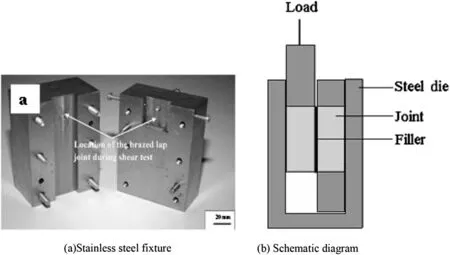
Fig. 1. Stain less steel fixture and its schematic diagram used to test the shear strength of the welds.
Thermal shock failure due to crack initiation can be decreased by reducing Young's modulus (E) and co-efficient of thermal expansion (CTE) by preheating. Though CTE is not strongly affected by change in temperature, E decreases with increase in temperature [27—29]. Young's modulus of ZrB2was reported to be decreased by 50% from 524 GPa at room temperature to 263 GPa at 1600°C. This change in E is equal to approximately double the crack initiation thermal shock resistance [27]. King et al. [21] reported the plasma arc welding of TiB2—20 vol % TiC composites and ZrB2-20 vol % ZrC composites [22] by preheating of weld coupons. Even after preheating to a temperature of 1450°C and controlled cooling after welding, the formation of porosity is observed at weld interface.
Molten liquid of ZrB2composite will form upon striking an arc between tungsten electrode and the solid surface of the composite. As the molten pool is cooled, the solid joint surfaces are bonded together. Due to shrinkage accompanied by solidification of melt pool, the formation of some porosity at solid—liquid boundary between parent material and fusion zone is possible. During welding, the oxidation of the parent material can also lead to escape of gaseous species like SiO, CO, and B2O3,and induce porosity in the fusion zone. A suitable filler material is required to avoid the formation of cracks and pores during welding. Filler forms a liquid pool and fills the gap between the surfaces to be joined. It is similar to metal casting into a mold. By properly controlling the welding speed the flow of the filler liquid into butt weld gap can be controlled to avoid cracks and pores that could form due to shrinkage during the solidification of molten filler.
The filler material should have more flowability and oxidation resistance compared to parent material. It should flow into the butt chamfers easily. To suit the above requirements, high vol.% of B4C and YAG were taken for the filler material (ZrB2—25 vol.% SiC—25 vol.% B4C—16 vol.% YAG). The filler material was sintered into cylindrical shapes with 30 mm in diameter and 10 mm in height and welding rods with 3 mm in diameter and 7.5—10 cm in length. The typical microstructure and XRD pattern of filler composite are shown in Fig. 3.
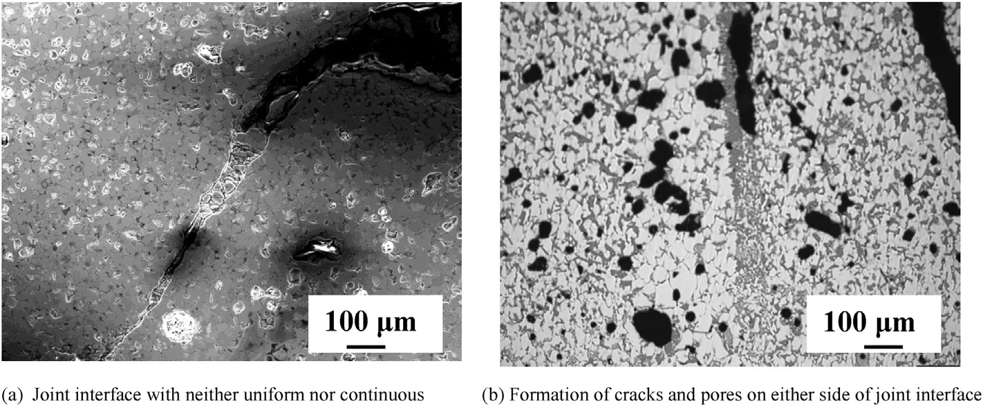
Fig. 2. Optical photo micrographs of gas tungsten arc fusion weld of (ZSBY) without filler.
3.2. Exposure to high temperature flame
Further the 30 mm diameter and 10 mm height pressureless sintered compact of filler material of (ZrB2—SiC—B4C-YAG)composite was exposed to oxyacetylene flame at 2200°C and plasma flame at 2700°C (Fig. 4(a) and (c)). The flame temperature and the sample temperature immediately after withdrawing the flame have been measured (Fig. 4(a) and (b)). The sample was exposed to oxyacetylene flame for 1—1.5 min before the withdrawal of the flame and allowed to cool naturally for 1 min. The sample was subjected to above thermal cycle for 20 times. The sample retained its shape and dimension even after 20 cycles of exposure to oxyacetylene flame at 2200°C (Fig. 4(d)). The weight change of +4.0 mg/ cm-2was recorded. After continuous exposure to plasma flame at 2700°C for 10 min, the sample experienced a weight loss of -27.87 mg/cm-2. The appearance of the sample is shown in Fig. 4(e)). The weight change values obtained for this filler material are considerably lower than those values reported for ZrB2-20 vol. % SiC composites [30,31].
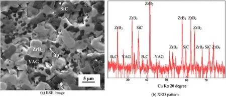
Fig. 3. BSE image and XRD pattern of Sintered (ZSBY)filler material.
The XRD analysis of the sample exposed to plasma flame or oxyacetylene flame revealed the formation of yttriastabilized zirconia layer on the surface (Fig. 5). Passive oxidation protection is expected by the continuous and dense ZrO2layer which prevents the ZrB2—SiC composite from directly exposing to air. ZrO2cannot adhere to ZrB2at high temperature and causes cracking. Spalling tend to occur due to the weak bonding that results from mismatch of coefficient of thermal expansion between the oxide scale and unaltered ZrB2matrix [32]. In the filler composite due to the formation of gloss of YAG, the YSZ layer will adhere to the parent composite and protect the composite from further oxidation.
3.3. Gas tungsten arc melting of filler material
The sintered rods of filler material were initially tested for gas tungsten arc melting using a water cooled mild steel bowl. The difference in structure and morphology of phases after arc melting can be seen in Fig. 6(a). Typical dendritic morphology has been observed in solidified filler material. In spite of water cooling, the molten filler material reacted and strongly adhered with mild steel bowl (Fig. 6(b)). ZrB2/FeB composite coating is expected to improve the mechanical strength, hardness and wear resistance of steel [32]. After successful melting of the filler material by gas tungsten arc, the filler rods were used for welding of ZS and ZSBY composite samples.
3.4. Gas tungsten arc welding
Sintered compacts with 10 mm in diameter×10 mm in height and 30 mm diameter×10 mm in height of ZSBYcomposite were joined by GTAW. The joint interface between the parent material and filler material was very clean and coherent, as shown in Fig. 7(a). The Vickers microhardness number (VHN) of the ZSBY joint across the interface was found to increase from 12.53 GPa to 17.83 GPa (Fig. 7(b)). The increase in VHN can be attributed to the increase in volume fraction of SiC, and B4C from parent compositetofillercomposite.Further,the 4×5×50 mm bars of ZS and ZSBY composites were welded to themselves using filler. The appearance of welds is similar to that of metal welds (Fig. 8(a) and (b)). In particular, the weld of ZSBY is very clean and free from crack and oxidation of either parent material or filler material. Formation of cracks and pores on either side of the joint inter face in heat effected zone (Fig. 2(b)) was observed in fusion welding without filler.
When an arc is created between tungsten electrode and the joint surface, a liquid pool is formed. As the molten pool is cooled, the joint surfaces are bonded together. Some porosity at boundary of parent material and fusion zone is expected due to shrinkage accompanied by solidification of melt pool. When filler is used, the composite filler forms a liquid pool and fills the gap between the surfaces to be joined. It is similar to metal casting into a mold. By properly controlling the welding speed the flow of the filler liquid into butt weld gap can be controlled to avoid the cracks and pores that could form due to shrinkage during the solidification of molten filler.
Cracking was observed in ZS weld after about 30 mm long joining. Oxidation of ZS parent material was observed. In ZSBY, the formation of a complex yttria alumina silicate glass has been expected to protect the composite from oxidizing. Since the ZSBY and filler material are of similar composition, the thermal stresses could be low enough to avoid cracking. In ZS, the high thermal stresses within the parent material can lead to cracking due to high melting point and high volume fraction of ZrB2(Fig. 8(c)). The difference in composition between the filler material and ZS parent material can also lead to cracking in the weld zone (Fig. 8(d)). It is interesting to notice that ZS composite was severely oxidized and in some areas the oxide layer was pulled onto the molten filler material which exhibited very good oxidation resistance.

Fig. 6. Optical photo micrographs: Gas tungsten arc melted (ZSBY)filler material (F.M.).
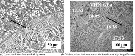
Fig. 7. Gas tungsten arc weld of (ZSBY) composites with (ZSBY)filler material.
In spite of cracking after 3/4th length of the joint and oxidation of ZS, in general, the weld interfaces are very clean, continuous and free from agglomeration and porosity in both ZS and ZSBY (Fig. 9). The VHN across the interface fromparent material to filler material in weld zone

Fig. 8. The appearance of gas tungsten arc welding.
(Fig. 9(b)) increased from 17.18 GPa to 24.93 GPa. The increase in hardness from ZS to filler and from ZSBY to filler can be attributed to the high vol % of both SiC and B4C in the filler material. BSE image analysis also revealed the formation of different phases after arc welding (Fig. 10(a)). The different phases in BSE image were identified through EDS analysis (Fig. 10(b)): bright phase as ZrB2, light grey phase as SiC, dark grey phase as ytrria alumina silicate and black phase as complex yttria-alumina-silicate containing SiC/ZrC.
ZSBY welds were subjected to shear testing. They were failed in weld interface zone. The typical morphology of fracture surface revealed the cleavage/brittle mode fracture (Fig. 10(c)). The calculated shear strength was 100 MPa. The present results revealed the possibility of GTAW of ZS and ZSBY composites with filler material. Without preheating and ost controlled cooling, the parts could be welded by manual operation. Further improvement in welding of ZS appears to be possible by altering the composition of the filler material. The combination of preheating of weld coupons in protective atmosphere and use of filler composite is very promising for successful GTAW of ZS.
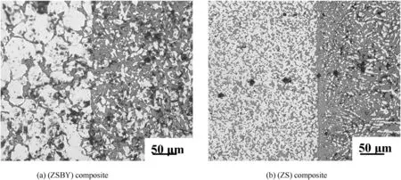
Fig. 9. Optical photo micrographs showing the weld interfaces, shown in Fig. 6 (right side:filler material).
4. Conclusions
1) A filler material of (ZrB2—SiC—B4C-YAG) composite with oxidation resistance and thermal shock resistance was produced in the form of welding wire.
2) The possibility of GTAW of ZrB2—SiC based ultra-high temperature ceramic composites to themselves without preheating, post controlled cooling and extraneous protective gas shield was demonstrated.
3) Hot pressed ZrB2—SiCand pressurelessly sintered ZrB2—SiC—B4C-YAG composites were joined to themselves using the composite filler.
4) The fusion welding resulted in cracking and non-uniform joining without any filler material.
5) The weld interfaces for both the composites were very clean and coherent.
6) The Vickers micro-hardness across the weld interface was found to increase due to the increase in the volume % of both SiC and B4C in the filler material.
7) The shear strength of the weld was about 50% of the flextural strength of the parent composite.
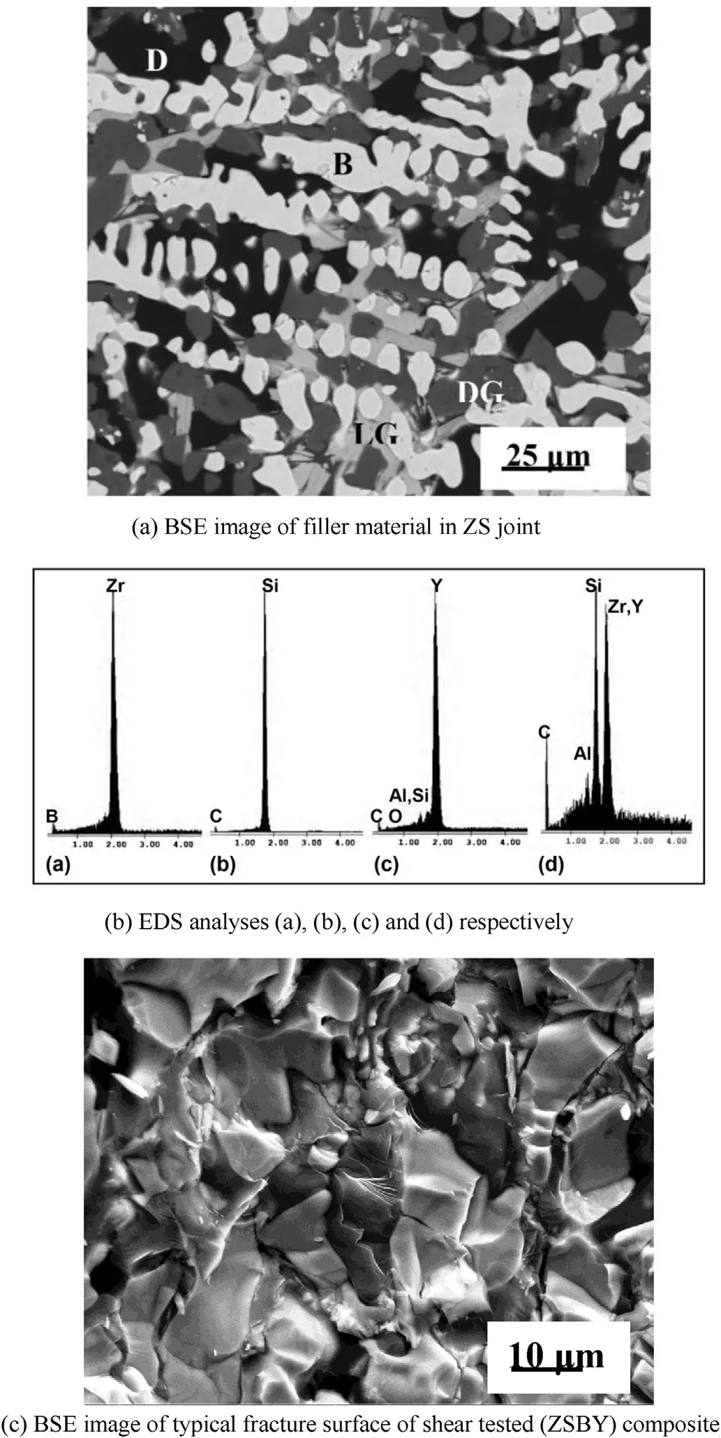
Fig. 10. (a) BSE image of filler material in ZS joint. B = bright phase, LG = light grey phase, DG = dark grey phase and D = black phases and their corresponding (b) EDS analyses (a), (b), (c) and (d) respectively, and (c) BSE image of typical fracture surface of shear tested (ZSBY) composite.
Acknowledgments
The authors thankfully acknowledge the financial support from the Defence Research and Development Organization, Ministry of Defence, Govt. of India, New Delhi in order to carry out the present study. They are grateful to Director, DMRL, Hyderabad, for his constant encouragement. The authors acknowledge the support of XRD, SEM groups of DMRL.
References
[1] Opeka MM, Talmy IG, Zaykoski JA. Oxidation based materials selection for 2000°C hypersonic aero surfaces: theoretical considerations and historical experience. J Mater Sci 2004;39:5887—904.
[2] Guo SQ, Nishimura T, Mizuguchi T, Kagawa Y. Mechanical properties of hot-pressed ZrB2-MoSi2-SiC composites. J Eur Ceram Soc 2008;28:1891—8.
[3] Zou J, Zhang GJ, Kan YM, Wang PL. Pressureless densification of ZrB2—SiCcompositeswithvanadiumcarbide.Scr Mater2008;59:309—12.
[4] Guo SQ. Densification of ZrB2-based composites and their mechanical and physical properties: a review. J Eur Ceram Soc 2009;29:995—1011.
[5] Jayaseelan DD, Wang Y, Hilmas GE, Fahernholtz W, Brown P, Lee WE. TEM investigation of hot-pressed 10 vol % SiC-ZrB2composite. Adv Appl Ceram 2011;110:1—7.
[6] Tian W, Kita H, Hyuga H, Kondo N, Nagaoka T. Reaction joining of SiC ceramicsusingTiB2-basedcomposites.JEur Ceram Soc2010;30:3203—8.
[7] Lin YJ, Tu SH. Joining of mullite ceramics with yttria aluminasilicate glass interlayers. Ceram Int 2009;35:1311—5.
[8] Goretta KC, Gutierrez-Mora F, Picciolo JJ, Routbort JL. Joining alumina/ zirconia ceramics. Mater Sci Eng A 2003;341:158—62.
[9] Asthana R, Singh M. Joining of partially sintered alumina to alumina, titanium, hastealloy and C-SiC composite using Ag-Cu brazes. J Eur Ceram Soc 2008;28:617—31.
[10] Li S, Chen X, Chen Z. The effect of high temperature heat treatment on the strength of C/C-SiC joints. Carbon 2010;48:3042—9.
[11] Dourandish M, Simchi A, Hokamoto K, Tanaka S. Interface formation and bond strength in 3Y-TZP/Cr composite bi-layers produced by sinterjoining. Mater Sci Eng A 2010;527:449—53.
[12] Esposito L, Bellosi A. Joining ZrB2-SiC composites using glass interlayers. J Mater Sci 2005;40:4445—53.
[13] Muolo ML, Ferrera E, Passerone A. Wettability of zirconium diboride ceramics by Ag, Cu and their alloys with Zr. Scr Mater 2003;48:191—6.
[14] Singh M, Asthana R. Joining of zirconium diboride-based ultra hightemperature ceramic composites using metallic glass interlayers. Mater Sci Eng A 2007;460:153—62.
[15] Asthana R,Singh M.Joining of ZrB2-basedultra-high-temperature ceramic composites using Pd-based braze alloys. Scr Mater 2009;61:257—60.
[16] Bo Yuan, Zhang GJ. Microstructure and shear strength of self-joined ZrB2and ZrB2-si with pure Ni. Scr Mater 2011;64:17—20.
[17] He Peng, Yang Weiqi, Lin Tiesong, Jia Dechang, Feng Jicai, Liu Yu. Diffusion bonding of ZrB2-SiC/Nb with in situ synthesized TiB whiskers array. J Eur Ceram Soc 2012;32:4447—54.
[18] Yang Weiqi, He Peng, Lin Tiesong, Song Changbao, Li Ruishan, Jia Dechang. Diffusion bonding of ZrB2-SiC and Nb using dynamic compressed Ni foam interlayer. Mater Sci Eng A 2013;573:1—6.
[19] Gasparov VA, Sidorov NS, Zver’kova II, Kulakov MP. Electron transport in diborides: observation of super conductivity in ZrB2. J Exp Theor Phys Lett 2001;73:532—5.
[20] Brown HJ, Fahrenholtz WG, Hilmas GE. Fusion welding of ZrB2-based ceramics. in: ultra-high temperature ceramics: materials for extreme environmental applications II. ECI Symp Ser 2013;P16. http://dc. engconfintl.org/uhtc/13.
[21] King DS, Hilmas GE, Fahrenholtz WG. Plasma arc welding of TiB2-20 vol% TiC. J Am Ceram Soc 2014;97:56—9.
[22] King DS, Hilmas GE, Fahrenholtz WG. Plasma arc welding of ZrB2-20 vol.% ZrC ceramics. J Eur Ceram Soc 2014;32:3549—57.
[23] Krishnarao RV, Alam Md Zafir, Das DK, Bhanuprasad VV. Synthesis of ZrB2-SiCcomposite powder in air furnace. CeramIntnl 2014;40:15647—53.
[24] Hasselman DPH. Thermal stress resistance parameters for brittle refractory ceramics: a compendium. Ceram Bull 1970;49(12):1033—7.
[25] Munz D, Fett T. Thermal shock behaviour. In: Muntz D, Fett T, editors. Ceramics-mechanical properties, failure behaviour, materials selection. Berlin: Springer Verlag; 1999. p. 203—26.
[26] Zimmermann JW, Hilmas GE, Fahrenholtz WG. Thermal shock resistance of ZrB2and ZrB2-30% SiC. Mater Chem Phys 2008;112:140—5.
[27] Neuman EW, Hilmas GE, Fahrenholtz WG. Strength of zirconium diboride to 2300°C. J Am Ceram Soc 2013;96(1):47—50.
[28] Wachtman JB, Lam DG. Young's modulus of various refractory materials as a function of temperature. J Am Ceram Soc 1959;42(5):254—60.
[29] Rhodes WH, Clougherty EV, Kalish D. Research and development of refractory oxidation-resistant diborides. Part II.Volume IV. Mechanical properties. AFML-TR-68-190(Pt.2), vol. 4. OH: Wright Patterson Air Force Base; 1970.
[30] Han J, Hu P, Zhang X, Meng S. Characteristics and mechanisms of dynamic oxidation for ZrB2-SiC based UHTC. Key Eng Mater 2008;368—372:1722—6.
[31] Zhang X, Hu P, Han J, Meng S. Ablation behavior of ZrB2-SiC ultra high temperature ceramics under simulated atmospheric re-entry conditions. Comp Sci Tech 2008;68:1718—26.
[32] Guo LJ, Wang XB, Zhang PP, Yang ZH, Wang HB. Synthesis of Fe based ZrB2compositecoatingbygastungstenarcwelding.MST2013;29:19—23.
* Corresponding author.
- Defence Technology的其它文章
- Influence of tool pin profile on microstructure and corrosion behaviour of AA2219 Al
—Cu alloy friction stir weld nuggets Ch. VENKATA RAOa, G. MADHUSUDHAN REDDYb, K. SRINIVASA RAOa,* - Optimization of process parameters of aluminum alloy AA 2014-T6 friction stir welds by response surface methodology Ramanjaneyulu KADAGANCHIa, Madhusudhan Reddy GANKIDIb,*, Hina GOKHALEb
- Effect of hot-humid exposure on static strength of adhesive-bonded aluminum alloys
- Numerical modeling of friction stir welding using the tools with polygonal pins M. MEHTAa, G.M. REDDYb, A.V. RAOb, A. DEc,*
- Microstructure and pitting corrosion of shielded metal arc welded highnitrogen stainless steelRAFFI MOHAMMEDa, G. MADHUSUDHAN REDDYb, K. SRINIVASA RAOa,*
- Characterization of magnetically impelled arc butt welded T11 tubes for high pressure applications R. SIVASANKARIa, V. BALUSAMYa, P.R. VENKATESWARANb,*, G. BUVANASHEKARANb, K. GANESH KUMARb

