Mechanical behaviors of steel reinforced ECC/concrete composite columns under combined vertical and horizontal loading
Shan Qifeng Pan Jinlong Chen Junhan
(Key Laboratory of Concrete and Prestressed Concrete Structures of Ministry of Education, Southeast University, Nanjing 210096, China)
Mechanical behaviors of steel reinforced ECC/concrete composite columns under combined vertical and horizontal loading
Shan Qifeng Pan Jinlong Chen Junhan
(Key Laboratory of Concrete and Prestressed Concrete Structures of Ministry of Education, Southeast University, Nanjing 210096, China)
In order to improve the load capacity, seismic performance and performance-cost ratio of the columns, the concrete at the base of reinforced concrete (RC) columns is substituted with engineered cementitious composites (ECC) to form ECC/RC composite columns. Based on the existing material properties, the mechanical behaviors of the ECC columns, ECC/RC composite columns and RC columns were numerically studied under combined vertical and horizontal loading with the software of ATENA. Then, the failure mechanism of ECC columns and ECC/RC composite columns were comprehensively studied and compared with that of the RC columns. Then, the effects of the height of the ECC, the axial compression ratio, and the transverse reinforcement ratio on the mechanical behaviors of the composite or the ECC column are studied. The calculation results show that the ultimate load capacity, ductility and crack resistance of the ECC or ECC/RC composite columns are superior to those of the RC columns. The ECC/RC composite column with a height of the ECC layer of 1.2h(his the height of the cross section) can achieve similar mechanical properties of a full ECC column. With high shear strength, ECC can undertake the shear force and significantly reduce the amount of stirrups, avoiding construction issues and promoting its engineering application.
engineered cementitious composites (ECC); ECC/RC composite columns; compression-bending behavior; numerical analysis; parametric analysis
China is an earthquake-prone country and has suffered from a few serious earthquakes, which caused tremendous economic and life loss. Previous earthquake damage investigations show that the frame structures, especially short columns, exhibit shear failure due to the brittleness and deficiency in the shear strength of the concrete[1]. To increase the seismic performance of frame structures, the columns are reinforced with additional transverse reinforcement, which serves as confinement of the core concrete and leads to enhancement of the shear capacity. With additional transverse reinforcement, brittle shear failure can be avoided. However, for reinforced concrete structures, though transverse reinforcement can provide composite action with concrete and achieve virtually ductile deformation behavior, the inherent brittleness of concrete cannot be improved and its deficiency with respect to steel/concrete interaction and interfacial bond deterioration are still challenges for conventional reinforced concrete. To modify the brittleness of concrete and increase the interfacial bond between concrete and steel reinforcement using fiber reinforced concrete (FRC) is proposed to substitute the concrete in the column. FRC is a kind of high performance concrete with high strength and resilience. However, for the FRC material, after the first crack is formed, tensile softening still occurs. Hence, FRC cannot maintain tensile strength under a continuous increase in tensile strain, resulting in limited improvement of seismic resistance by using FRC.
In recent years, a class of high performance fiber reinforced cementitious composites with ultra-ductility has been developed for application in the construction industry[2]. The ultimate elongation can reach 3% to 5% subjected to uniaxial tensile load, with a crack spacing of 3 to 6 mm and a crack width of about 100 μm[3-4]. It is designed based on micromechanics, which is used as the basis for the tailoring of fiber, matrix and interface[5-8]. Studies have shown that the use of ECC materials in engineering structures can significantly improve the bearing capacity, ductility and energy dissipation of the structures[9-14]. Thus, the substitution of concrete with ECC in the RC column has better seismic performance. However, due to the high cost of ECC compared with concrete, the application of ECC for a whole column is not economic. Therefore, the present study proposes replacing the concrete with ECC at the base zone of the column where the maximum moment occurs. The ECC/RC composite columns are expected to reduce the cost of materials but to ensure maximum seismic performance and make their application in practical engineering economically feasible.
Few studies on the seismic performance of ECC/RC composite columns have been reported currently, and it is particularly necessary to carry out relevant research work to promote their engineering applications. Therefore, based on the material properties tested in our group[15-16], ECC or ECC/RC composite columns and RC columns were numerically simulated under combined vertical and horizontal loading with the software of ATENA. Then, the failure mechanisms of the ECC column and ECC/RC composite column were comprehensively studied and compared with that of the RC column, which is valuable for reference in real engineering applications.
1 Numerical Modeling of ECC/RC Composite Columns
1.1 Stress-strain relationship
In this study, the software of ATENA is employed to conduct the numerical analysis. This software is suitable for a nonlinear mechanical analysis of concrete structures, and the validity by using the software has been verified by the experimental results of the steel reinforced ECC and ECC/RC composite beams[17]. In this simulation, concrete is modeled by the elements of “3D Nonlinear Cementitious 2” with the stress-strain relationship shown in Fig.1. The parameters of the stress-strain relationship of concrete are listed in Tab.1.
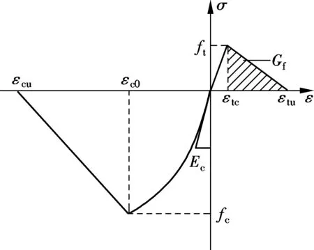
Fig.1 Stress-strain relationship of concrete
Tab.1 Parameters of stress-strain relationship of concrete

fc/MPaεc0εcuEc/GPaft/MPaGf/(N·m-1)38.20.0020.003332.952.8281.43
ECC material is modeled by the elements of “3D Nonlinear Cementitious 2 User”, and the stress-strain relationship of ECC is shown in Fig.2. The typical parameters of the ECC stress-strain curve are obtained from uniaxial tension and compression tests, as shown in Tab.2[15-16].

Tab.2 Parameters of stress-strain relationship of ECC
The steel reinforcement is described by a bilinear curve with strain hardening (see Fig.3). The yield strength, ultimate strength of steel reinforcement are 460 and 600 MPa, respectively. The ultimate tensile strain is 0.08 and the modulus of elasticity is 200 GPa.
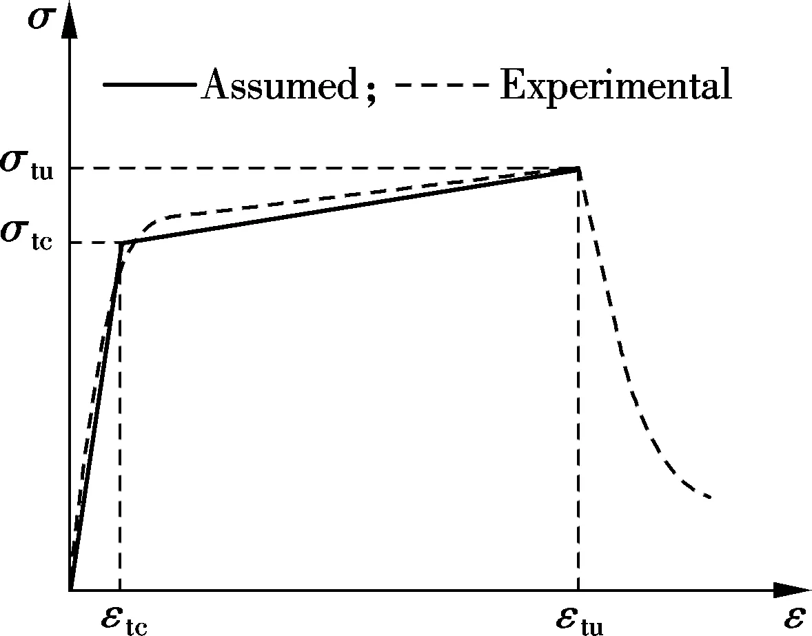
(a)
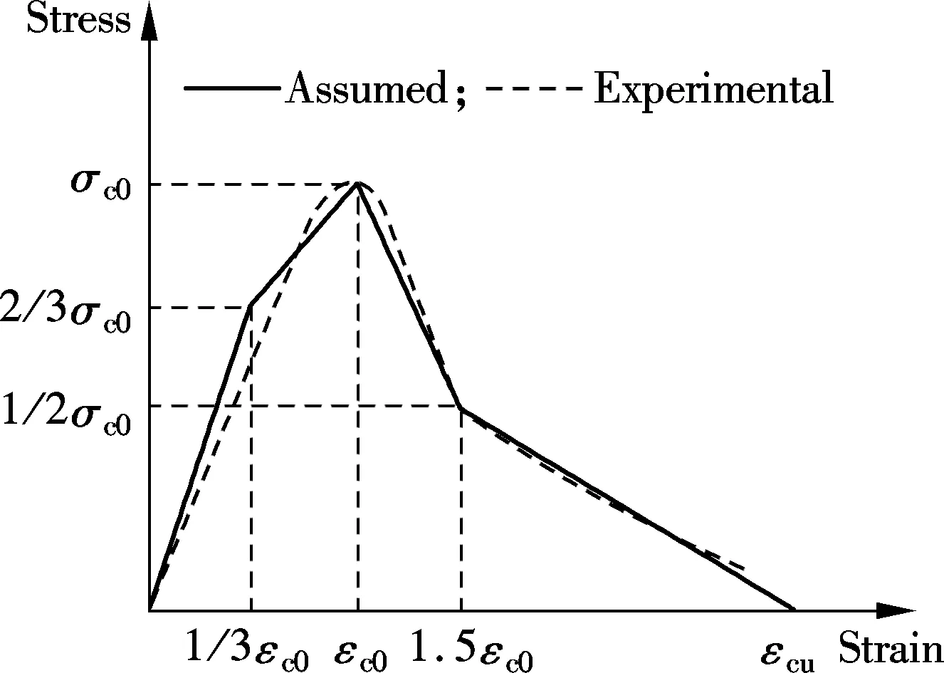
(b)
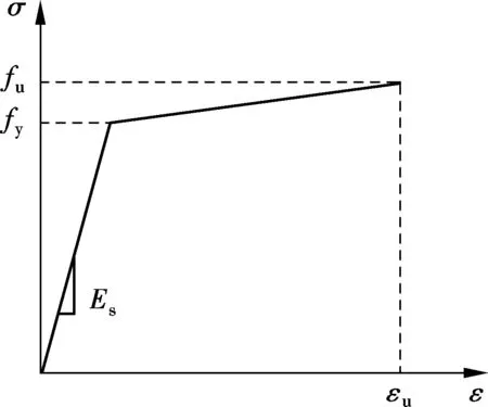
Fig.3 Stress-strain relationship of reinforcement
1.2 Finite element model
The columns are simulated herein using the constitutive models described above. The dimensions of the cross section of the columns are 250 mm×250 mm, and the heights of the columns are 1 100 mm and 600 mm. The horizontal load is applied at 1 000 mm and 500 mm from the top of foundation, respectively, indicating that the shear span ratios for the two types of columns are 4.0 and 2.0, respectively. The columns are reinforced with four 16-mm-diameter bars symmetrically. They are designed with proper stirrups with the diameter of 8 mm and the spacing of 150 mm in shear span.
Three-dimensional finite element models are adopted for this study. The finite elements model of the ECC/concrete composite columns are shown in Fig.4 and the parameters of the columns are shown in Tab.3. In this analysis, the base of the foundation beam is fully fixed. The spring elements are used to consider the bond behavior between the steel bars and the matrix (concrete or ECC). The bond-slip model of the interface elements is defined based on the “CEB-FIP Model Code 1990”[18]. Perfect bond between concrete and the ECC layer is assumed in the finite element analysis. The columns are loaded with displacement control during the loading process. The “Newton-Raphson” iterative procedure is selected as the solution method. Both displacement and residual convergence criteria are adopted in the computation and the error tolerance is set to be 0.01.
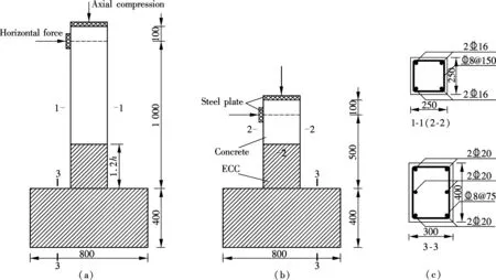
Fig.4 Finite element models of ECC/concrete composite columns. (a) Column; (b) Short column; (c) Column sections (unit: mm)
Tab.3 Parameters of columns

Specimenl/mmuHEρ/%ρv/%fc/MPaf′c/MPaRC⁃L10000.2301.50.66838.238.3E/R⁃L10000.231.2h1.50.66838.238.3ECC⁃L10000.23l1.50.66838.238.3RC⁃S5000.4501.50.66838.238.3E/R⁃S5000.451.2h1.50.66838.238.3ECC⁃S5000.45l1.50.66838.238.3

2 Calculation Results and Discussion
2.1 Failure mechanism and cracking patterns of long columns
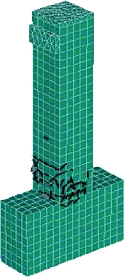
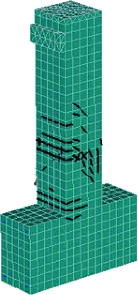
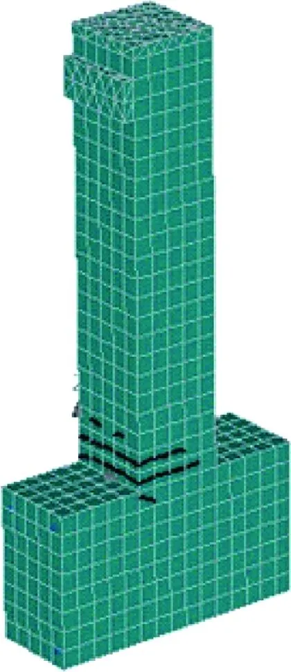
The cracking patterns of the columns with an effective height of 1 000 mm in the ultimate stage are shown in Fig.5, and the calculation results of the specimens are shown in Fig.6 and Tab.4. In general, all the specimens (including RC, ECC and E/R columns) fail in the flexural model. The final failure of the composite column is due to the major crack occurring at the base of the column, which is similar to the RC or ECC column. According to the calculation results, the peak loads of the composite column and ECC column are 31.42% and 35.83% higher than that of the RC column, respectively. The ultimate displacements of the composite and ECC columns are 31.44% and 35.83% larger than that of the RC column. The ductility coefficients of the composite and ECC columns are 4.00 and 4.13, which are 12.04% and 15.69% larger than that of the RC column, respectively. Interestingly, the ECC/concrete composite column with the ECC height of 1.2hshows very similar mechanical behaviors (including the peak load, the ultimate displacement and the ductility coefficient) with the ECC column.
(a)
(b)
(c)
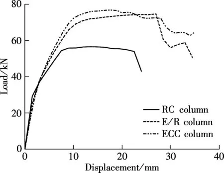
Fig.6 Load-displacement curve of columns
For the RC column, the cracks concentrate on the base of the column. For the ECC/concrete composite column, the cracks concentrate on the interface between the concrete and ECC, but the maximum crack width is much smaller than that of the RC column, which is due to the well crack controlling ability of ECC material. When the tensile steel reinforcement starts to yield, the crack width of the RC column is 0.74 mm, which is much larger than the limit value for concrete structures from the Code for Design of Concrete Structures (GB 50010—2010)[19], while the maximum crack width of the composite column or ECC column is only 0.38 or 0.18 times that of the RC column. With the increase in the displacement to the peak point, the maximum crack width of the RC column reaches 1.63 mm, while it is controlled to be approximately 0.64 and 0.4 mm in the composite column and the ECC column, respectively. The maximum crack width in the RC column is much larger than that of the composite column or the ECC column, indicating that the use of ECC can greatly reduce the crack width at the base of column at different stages.

Tab.4 Calculation results of each column specimen
2.2 Failure mechanism and cracking patterns of short columns
The cracking patterns of the columns with an effective height of 500 mm in the ultimate stage are shown in Fig.7 and the calculation results of the specimens are shown in Fig.8 and Tab.4. For the RC short column, the column fails due to the brittle shear failure of concrete with the yield of transverse steel reinforcement, while the composite and ECC short columns exhibit flexural failure by the formation of a major flexural crack at the base of the column after the longitudinal reinforcement yield. Compared with the RC short column, the peak loads of the composite and ECC short columns are 36.29% and 38.13% higher than that of the RC short column, respectively. The ultimate displacements of the composite and ECC columns are larger than that of the RC column by 40.39% and 43.57%, respectively. The ductility coefficients of the composite and ECC short columns are 4.10 and 4.04, which are 22.8% and 21.0% larger than that of the RC column, respectively.
The maximum crack widths of the composite and ECC short columns are smaller than that of the RC short column during the loading process, which shows a similar trend to the long columns. When the columns start to yield, the crack width of the RC short column is 1.03 mm, which is 2.94 and 3.12 times those of the composite and ECC short columns respectively. The crack width of the RC column exceeds 1.91 mm at the peak load. However, with the ECC application in the columns, the maximum crack width can be controlled to approximate 1.31 mm. This is attributed to the fiber bridging effect and effective crack controlling ability of the ECC. For the RC column, the crack width increases rapidly after the first cracking and the deformation of the column is accompanied by a limited number of cracks. In contrast, for the ECC column, the deformation of the column is accompanied by multiple cracking in the ECC before crack localization occurs.
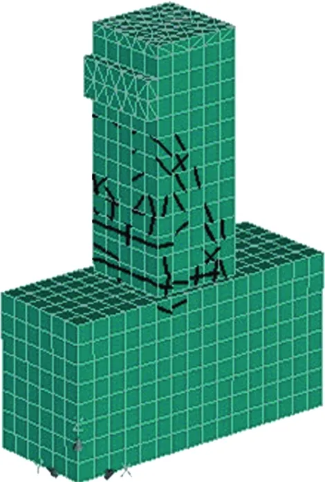
(a)
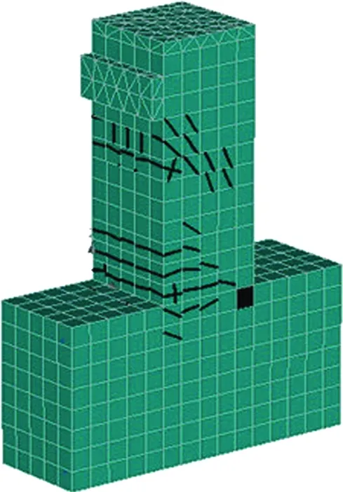
(b)
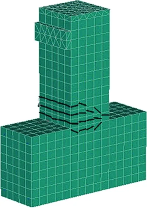
(c)
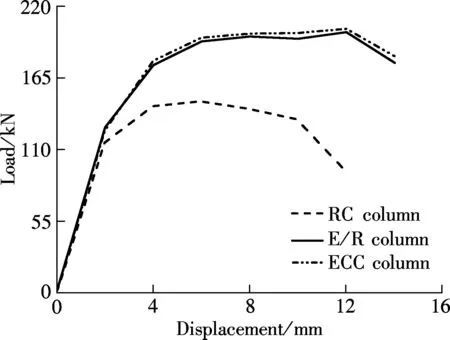
Fig.8 Load-displacement curve of short columns
3 Parametric Analysis
It is proved from the above analysis that the substitution of concrete with ECC at the base of the column can avoid the shear failure of short columns and significantly improve the strength and ductility and effectively control the width of cracks. In this section, the effect of different parameters, including the height of the ECC layer, the axial compression ratio and transverse reinforcement ratio on the mechanical behaviors of columns are comprehensively studied, which is valuable for reference in real engineering applications.
3.1 Effect of the height of ECC layer
Since the cost of ECC material is much higher than that of conventional concrete, strategic application of ECC in concrete structures can effectively increase its performance-cost ratio. Hence, for an ECC/concrete composite column, a proper height of the ECC layer should be determined by a parametric study. Four specimens, Z-1, Z-2, Z-3 and Z-4, which represent the height of the ECC layers of 0.4h, 0.8h, 1.2handl, respectively, are numerically studied to evaluate the effect of the height of the ECC on the mechanical behaviors of the composite column. Fig.9 shows the load-displacement curves of composite columns with different heights of the ECC layers.
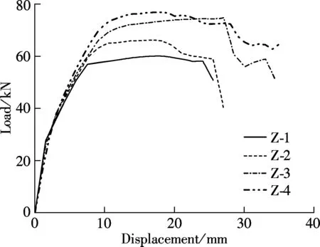
Fig.9 Load-displacement curve of composite columns with different heights of ECC layers
It is found from Fig.9 that a higher ECC layer can improve the ultimate strength and displacement of the composite columns. However, the increase amplitude of ultimate strength and displacement becomes smaller with the increase in the height of ECC layers. From Fig.9, the mechanical performance of Z-3 is very similar to that of Z-4. The ultimate strength and the ultimate displacement of Z-3 is 0.968 and 0.931 times those of Z-4, respectively, indicating that an ECC/concrete composite column with an ECC height of 1.2hcan almost achieve a similar mechanical performance to the full ECC column.
3.2 Effect of axial compression ratio
As is known to all, with the increase in the axial compression ratio, the peak load of the RC column tends to increase while the ultimate displacement tends to decrease. In this study, three axial compression ratios of 0.23, 0.45 and 0.68 are applied to specimens Z-23, Z-45 and Z-68 for mechanical analysis. The load-displacement curves of the specimens are shown in Fig.10.
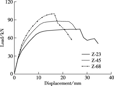
Fig.10 Load-displacement curve of composite columns with different axial compression ratios
According to the calculation results in Fig.10, with the increase in the axial compression ratio, the peak load of the composite column increases significantly while the ultimate displacement decreases, which follows the same trend as normal RC columns. The peak loads of Z-45 and Z-68 increase by 18.17% and 34.88% compared with those of Z-23 and the ultimate displacement is reduced by 10.34% and 34.61%, respectively. The ductility coefficients of Z-45 and Z-68 are 2.97 and 2.24, which are 25.74% and 44% lower than that of Z-23, respectively. This indicates that the reduction of the ductility coefficient is nonlinear with the increase in the axial compression ratio.
3.3 Effect of transverse reinforcement ratio
The transverse reinforcement ratio is an important parameter affecting the mechanical behavior of the RC columns. A small transverse reinforcement ratio may lead to the brittle shear failure in the RC columns. Existing studies show that the shear strength of ECC is much higher than that of concrete[3]. To prove the advantage of ECC in enhancing the shear capacity of columns, six column specimens are designed and simulated with different transverse reinforcement ratios (0, 0.4% and 0.67%) and different matrices (concrete and ECC). The load-displacement curves of columns with different stirrup ratios and matrices are presented in Fig.11. For RC-0 and RC-40, the load suddenly decreases at the displacement of 3 and 10 mm, respectively, and the maximum compressive strain of the cross section cannot reach the ultimate strain of concrete, indicating that the two columns fail in brittle shear failure due to the insufficiency of the stirrups. For RC-67, it exhibits flexural failure due to concrete compression failure after the yield of the tensile steel reinforcement in the cross section. However, three ECC columns with different transverse reinforcement ratios show the same failure mode, i.e., the flexural failure due to the ECC compression failure after the yield of tensile steel reinforcement. For the ECC columns, the load increases linearly with the corresponding displacement before the yield of steel reinforcement. After that, the curves dramatically changed and kept almost horizontal until the ultimate strength is reached. The maximum displacement of the ECC column is 39 mm, which is much larger than that of the RC columns. In particular, the ECC column without transverse reinforcement, shows very similar mechanical behaviors as the other two ECC columns with transverse reinforcement ratios of 0.4 and 0.67, which indicates that the use of ECC can effectively enhance the shear capacity of columns and can fully replace the function of stirrups in the columns.
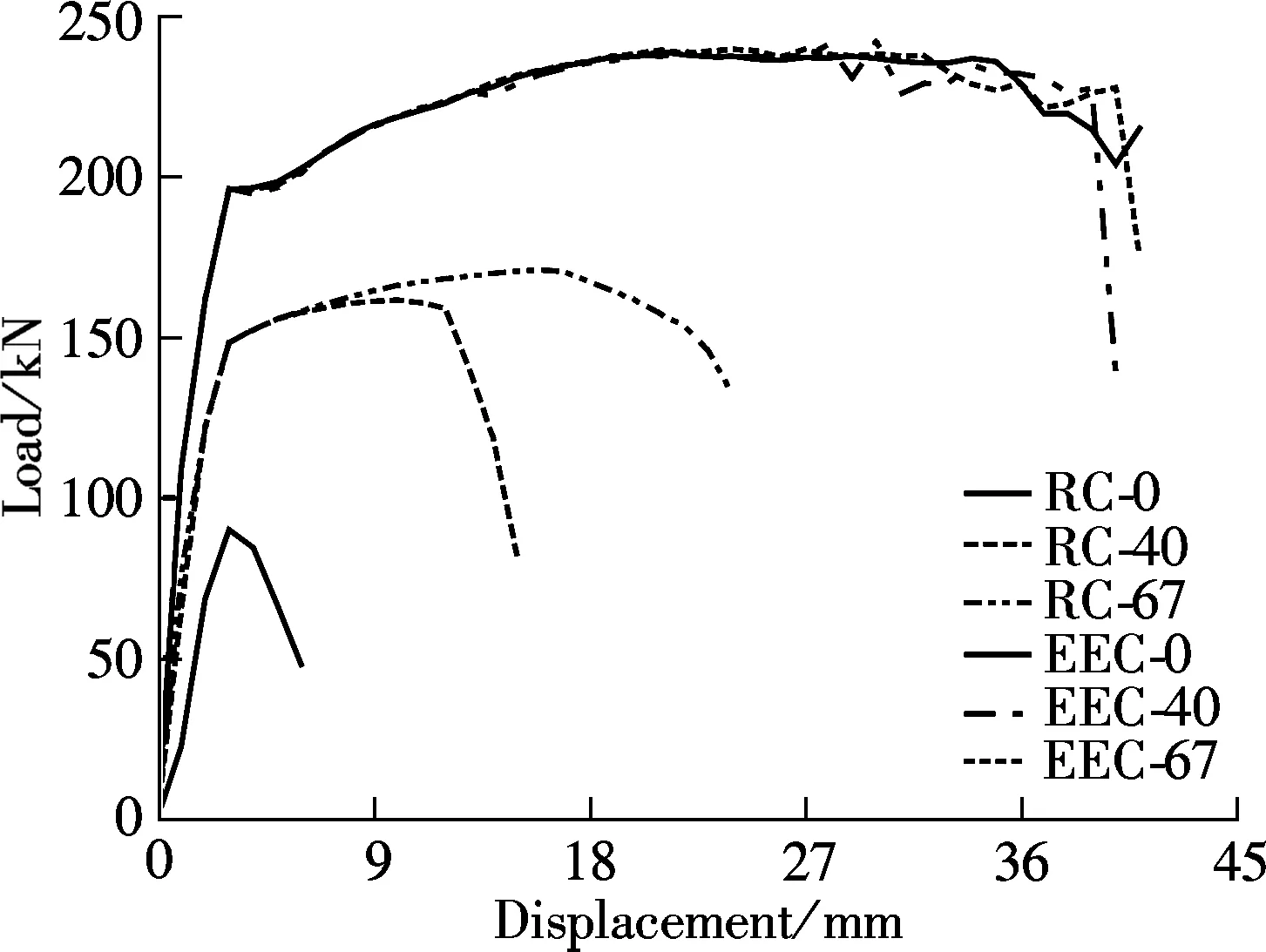
Fig.11 Load-displacement curve of columns with different stirrup ratios
4 Conclusions
In this paper, the mechanical behaviors of steel reinforced ECC/concrete composite columns under combined vertical and horizontal loading are numerically studied, as well as those of the RC and ECC columns. The failure mechanisms and crack patterns of three kinds of columns are discussed and compared. Then, a parametric study is conducted to illustrate the effects of the height of the ECC layer, axial compression ratio and transverse reinforcement ratio on the mechanical behavior of the ECC/concrete composite columns or ECC columns. The conclusions can be drawn as follows:
1) Substitution of concrete with ECC can lead to the change of the failure mode of the short column from brittle shear failure to flexural failure, and can effectively increase mechanical properties such as ultimate load capacity, ductility, and cracking resistance capacity.
2) A thicker ECC layer at the base can improve the peak load and ductility of the composite columns. The ECC/concrete composite column with a height of an ECC layer of 1.2hcan achieve similar mechanical performance of the whole ECC column.
3) The ultimate strength of the ECC/RC composite column or ECC column increases with the axial compression ratio. However, the ductility shows a clear decrease with the increase in the axial compression ratio.
4) The use of ECC can significantly enhance the shear capacity of the column and can fully replace the function of stirrups in the columns.
[1]Civil and Structural Groups of Tsinghua University, Xinan Jiaotong University and Beijing Jiaotong University. Analysis on seismic damage of buildings in the Wenchuan earthquake[J].JournalofBuildingStructures, 2008, 29(4): 1-9. (in Chinese)
[2]Kim Y Y, Fischer G, Li V C. Performance of bridge deck link slabs designed with ductile engineered cementitious composite[J].ACIStructuralJournal, 2004, 101(6):792-801.
[3]Li V C. On engineered cementitious composites (ECC)[J].JournalofAdvancedConcreteTechnology, 2003, 1(3): 215-230.
[4]Zhang J, Leung C K Y, Gao Y. Simulation of crack propagation of fiber reinforced cementitious composite under direct tension[J].EngineeringFractureMechanics, 2011, 78(12): 2439-2454.
[5]Li V C, Wang Y, Backer S. A micromechanical model of tension-softening and bridging toughening of short random fiber reinforced brittle matrix composites[J].JournaloftheMechanicsandPhysicsofSolids, 1991, 39(5): 607-625.
[6]Leung C K Y, Li V C. Effect of fiber inclination on crack bridging stress in brittle fiber reinforced brittle matrix composites[J].JournaloftheMechanicsandPhysicsofSolids, 1992, 40(6): 1333-1362.
[7]Li V C. Post-crack scaling relations for fiber reinforced cementitious composites[J].JournalofMaterialsinCivilEngineering, 1992, 4(1): 41-57.
[8]Li V C, Leung C K Y. Steady state and multiple cracking of short random fiber composites[J].JournalofEngineeringMechanics, 1992, 188(11): 2246-2264.
[9]Li V C. From micromechanics to structural engineering—the design of cementitious composites for civil engineering applications[J].JournalofStructuralMechanicsandEarthquakeEngineering, 1993, 10(2): 37-48.
[10]Li V C, Leung C K Y. Steady state and multiple cracking of short random fiber composites[J].JournalofEngineeringMechanics, 1992, 188(11): 2246-2264.
[11]Fukuyama H. Application of high performance fiber reinforced cementitious composites for damage mitigation of building structures[J].AdvanceConcreteTechnology, 2006, 4(1): 35-44.
[12]Parra-Montesinos G, Wight J K. Seismic response of exterior RC column-to-steel beam connections[J].JournalofStructuralEngineering, 2000, 126(10): 1113-1121.
[13]Park W S, Yun H D. Seismic performance of pseudo strain-hardening cementitious composite coupling beams with different reinforcement details[J].CompositesPartB:Engineering, 2011, 42(6): 1427-1445.
[14]Kim Y Y, Fischer G, Li V C. Performance of bridge deck link slabs designed with ductile ECC[J].ACIStructuralJournal, 2004, 101(6): 792-801.
[15]Yuan F, Pan J L, Leung C K Y. Flexural behaviors of ECC and concrete/ECC composite beams reinforced with basalt fiber-reinforced polymer[J].JournalofCompositeConstruction, 2013, 17(5):591-602.
[16]Zhou J J, Pan J L, Leung C K Y. Mechanical behavior of fiber reinforced engineered cementitious composites in uniaxial compression[J].JournalofMaterialsinCivilEngineering, 2015, 27(1):04014111
[17]Yuan F, Pan J L, Wu Y F. Numerical study on flexural behaviors of steel reinforced engineered cementitious composite (ECC) and ECC/concrete composite beams[J].ScienceChinaTechnologicalSciences, 2014, 57(3): 637-645.
[18]Comit E Euro-International Du B Eton. CEB-FIP model code 1990: design code[S]. London: Thomas Telford Ltd, 1993.
[19]Ministry of Housing and Urban-Rural Development of the People’s Republic of China. GB 50010—2010 Code for design of concrete structures [S]. Beijing: China Architecture and Building Press, 2010. (in Chinese).
钢筋增强ECC/混凝土组合柱压弯性能分析
单奇峰 潘金龙 陈俊涵
(东南大学混凝土及预应力混凝土教育部重点实验室,南京210096)
为了提高柱的承载力、抗震性能和性价比,采用工程水泥基复合材料 (ECC)材料替代钢筋混凝土(RC)柱柱根区域的混凝土形成ECC/RC组合柱.基于已有的材料性能试验数据,采用ATENA有限元软件对ECC柱、ECC/RC组合柱及RC柱的压弯性能进行数值分析.研究了ECC柱和ECC/RC组合柱的破坏机理,并与RC柱进行对比,进而探究ECC高度、轴压比和体积配箍率3个参数对ECC/RC组合柱或ECC柱压弯性能的影响.结果表明:ECC柱和ECC/RC组合柱较RC柱具有更高的承载力、延性和抗裂能力;ECC高度在1.2h(h为截面高度)左右的组合柱即可达到全ECC柱的性能效果;ECC具有较高的抗剪强度,能显著减小箍筋的配置,便于施工和促进实际工程应用.
工程水泥基复合材料 (ECC);ECC/RC组合柱;压弯性能;数值分析;参数分析
TU375
Foundation items:The National Natural Science Foundation of China (No.51278118), the Natural Science Foundation of Jiangsu Province (No.BK2012756), the Key Project of Ministry of Education of China (No.113029A).
:Shan Qifeng, Pan Jinlong, Chen Junhan. Mechanical behaviors of steel reinforced ECC/concrete composite columns under combined vertical and horizontal loading[J].Journal of Southeast University (English Edition),2015,31(2):259-265.
10.3969/j.issn.1003-7985.2015.02.018
10.3969/j.issn.1003-7985.2015.02.018
Received 2014-11-29.
Biographies:Shan Qifeng (1990—), male, graduate; Pan Jinlong (corresponding author), male, doctor, professor, jinlongp@gmail.com.
 Journal of Southeast University(English Edition)2015年2期
- Journal of Southeast University(English Edition)的其它文章
- Adaptive modulation in MIMO optical wireless communication systems
- An improving energy efficiency cooperation algorithm based on Nash bargaining solution in selfish user cooperative networks
- Performance analysis of an O2/CO2 power plantbased on chemical looping air separation
- Model of limestone calcination/sulfation under oxy-fuel fluidized bed combustion
- A novel carbon trap sampling systemfor coal-fired flue gas mercury measurement
- Applicability of Markov chain-based stochastic modelfor bubbling fluidized beds
