经颅脑肿瘤HIFU治疗技术的研究现状
韩珍珍,菅喜岐
(天津医科大学 生物医学工程与技术学院,天津300070)
1 前言
高强度聚焦超声(high intensity focused ultrasound,HIFU)肿瘤治疗具有无创、可重复治疗等优势[1],目前已应用于乳腺癌、子宫肌瘤、前列腺癌等实体软组织肿瘤的临床治疗[2]。对于如图1所示的经颅脑肿瘤HIFU治疗而言,颅骨与周边软组织声速及声阻抗差异大、颅骨的不均质和强衰减性等导致经颅聚焦超声(transcranial focused ultrasound,tcFUS)相位和幅值失真[3]。这些失真使得颅内散焦、焦点严重偏移目标靶区、颅骨处能量沉积而出现高温区域,导致颅骨周边正常组织损伤和目标靶区内肿瘤不能完全致死等临床问题的发生。1955年,Fry等[4~7]首次证实了在切除部分颅骨条件下HIFU应用于脑肿瘤治疗的可行性。为实现经颅脑肿瘤的HIFU无创治疗,必须通过相控换能器及其相关技术才能实现。1990年以来,随着相控换能器及其控制技术的发展,tcFUS无创治疗脑肿瘤成为可能,并受到众多研究者的广泛关注[8]。2009年,以色列InSightec公司研发的ExAblate 4000无创经颅治疗系统已应用于神经性疼痛[9]和特发性震颤[10]等脑功能障碍的临床试验(如图2所示)。

图1经颅脑肿瘤HIFU治疗示意图
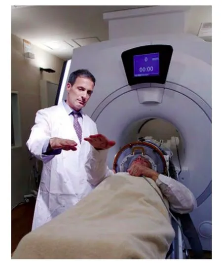
图2ExAblate 4000经颅脑肿瘤HIFU治疗系统临床试验(图片出处:http://www.insightec.com/)
2 相控换能器
相控换能器是经颅脑肿瘤HIFU治疗系统中最关键的部件之一,其激励频率、阵列基体参数、阵元参数等因素均对tcFUS脑肿瘤治疗效果有影响。
2.1 激励频率
采用与阵元谐振频率相同的激励信号触发阵元时,超声换能器的能量转化效率最高,阵元的工作状态最佳。超声频率越高,组织的吸收系数越大,对声能的吸收越强,焦域体积减小,且焦域最大温升位置会向换能器方向移动;频率越低,穿透组织的能力越强,焦域体积增大,空化阈值越小越易产生空化效应[11,12]。2005年,Hynynen等[13]采用0.25MHz的低频进行经颅仿真研究,结果表明低频虽在一定程度上降低了tcFUS相位和幅值的失真度,但空化效应风险增大。为此经颅治疗选择频率时,既要保证超声能够顺利地穿过颅骨到达目标靶区,又要在焦点处形成足够高的超声能量。1978年,Fry等[14]对0.25~6.0MHz范围内的频率进行筛选,发现tcFUS的频率在0.5~1.0MHz范围内时聚焦效果较好。
2.2 阵列基体参数
相控换能器由若干离散的阵元镶嵌在一定形状的基体上构成[15],基体一般有平面形和球面形,其中球面相控阵自身具有几何焦点,声强增益高[16]。目前tcFUS脑肿瘤治疗中主要采用球冠状相控换能器[17,18]和半球形相控换能器(如图3所示)。对于球冠状相控换能器而言,其焦域的可调控范
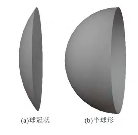
图3经颅治疗脑肿瘤相控换能器基体形状
围较大,但当目标焦点位置离颅骨表面由远及近时,颅骨内的声压呈增加趋势。就目前球面相控阵的控制技术而言,当焦点距离颅骨表面小于3cm时,颅骨中可能出现的高温升区域导致颅骨周围正常组织损伤[19]。对于半球形相控换能器而言,其几何结构可使颅骨表面的超声辐照面积最大化,颅骨中的热沉积最小[20],通过仿真与实验对比验证了半球形相控换能器可降低颅骨温升,但该换能器形成焦域的可调控范围较小,仅限于治疗深部脑肿瘤。2005年,Clement等[21]设计了开口直径30cm、激励频率0.7~0.8MHz的500阵元半球形换能器,研究结果表明该阵列可实现靶区脑组织的消融,不会对颅骨等正常组织造成损伤。2009年,以色列InSightec公司开发出ExAblate 4000系列无创经颅治疗系统,采用开口直径30cm、频率0.22或0.65MHz的1024阵元半球形相控换能器[22]。2013年,Chauvet等[23]设计了激励频率为1MHz的512阵元高功率半球形相控换能器用于经颅脑肿瘤治疗的仿真和离体实验,结果表明该阵列可实现目标靶区的有效消融。
2009年,吉翔等[24]的研究结果表明相控换能器基体的曲率半径趋近于最大扫描深度,开口直径大小决定了可能的最大偏离声轴距离,同时F值(曲率半径与开口直径的比值)越大聚焦深度越大,但越容易引起近距离正常组织的损伤,为避免近场正常组织的损伤F值需小于等于1.0[25]。
2.3 阵元参数
2.3.1阵元分布
阵元分布方式是tcFUS相控换能器优化设计的关键之一,常见的tcFUS相控换能器有规则分布和随机分布,其中规则分布中主要有扇蜗分布和活塞分布。
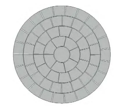
图4扇蜗分布
如图4所示的扇蜗分布换能器是将除中心阵元外的同心环状阵元均分成若干面积相等的四边形小阵元,每环的分割数目不等。通过对各阵元施加不同的相位延迟,可实现轴上变焦和离轴聚焦[26]。2000年,Clement等[27]设计了64阵元半球形扇涡阵,中心阵元为七边形,其周围阵元为四边形、四层同心环结构分布,阵元数目由内到外依次为7、13、20、23,仿真和离体实验结果均表明该阵列可经过颅骨在目标靶区产生损伤。2002年,Connor等[28]对500阵元的半球形扇蜗阵进行仿真实验,结果表明该阵列可实现靶区脑组织的无创消融,且不会造成周围正常组织的损伤。2013年,Narumi等[29]设计了56和256阵元中心开孔的球冠状扇蜗阵,仿真结果表明两种阵列均可实现tcFUS有效聚焦。
如图5所示的活塞分布换能器是将一定形状阵元(如矩形、菱形、圆形等)按一定方式(如六边形、同心环等)排布在球面基体内表面,通过调整相位可实现整个三维空间的调控聚焦[30]。2000年,Clement等[31]设计了相邻阵元中心间距相等的40矩形阵元相控阵,仿真结果表明该阵列可在目标靶区产生足够的声能量,且不会对颅骨等周围正常组织造成损伤。2001年,Sharifi等[32]对相同条件下矩形和圆形阵元相控阵的声场进行对比,结果表明圆形阵元可降低声场旁瓣、增大焦域能量。2010年,Matsumoto等[33]设计了以同心环方式分布的61圆形阵元活塞阵,基于人体头部CT图像建立的颅骨模型非线性仿真了tcFUS的声压场,结果表明该阵列可明显改善声场分布。2008年,Song等[34]采用长度为6mm、内径7.2mm、外径10mm的圆柱形阵元,设计了开口直径为310mm以同心环方式分布的1372阵元半球形相控换能器,激励频率为0.306或0.84MHz。
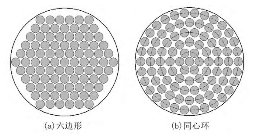
图5活塞分布(以圆形阵元为例)
如图6所示的阵元随机分布与圆形阵元的活塞分布类似,只是采取随机分布的阵元分布方式,使得相邻阵元的中心间距在一定范围内不等。2003年,Pernot等[35]对六边形、同心环、随机分布的200圆形阵元相控阵tcFUS的声压场进行仿真对比,结果表明随机分布相控阵可明显降低声场旁瓣。2007年,Tanter等[36,37]设计300圆形阵元随机分布的相控换能器,仿真结果表明该阵列可明显改善声场分布、不会损伤颅骨周围等正常组织。

图6随机分布
2.3.2阵元面积和数目
阵元面积的选择与阵元数目紧密相关,从理论上讲小的阵元面积,可以有效降低旁瓣、改善声场分布,但是面积越小越容易引起不同的振动方式,难以保证全部阵元以单一频率发射,且阵元面积越小阵元数目越多。1998年,Jie等[38]指出当阵元尺寸小于波长的5~6倍时,tcFUS聚焦效果最优。
2000年,Clement等[27]对相同条件下1、11、64、228、512阵元组成的半球形相控换能器进行仿真对比,结果表明随着阵元数目的增加,旁瓣数目逐渐减小、旁瓣声压幅值逐渐降低、焦域能量逐渐升高,然后趋于饱和。通过对tcFUS焦平面声场分布和主瓣声压幅值变化曲线比较得出在阵元数目为64时,就可以达到良好的聚焦效果。2013年,Narumi等[29]对56和256阵元球冠状相控换能器的tcFUS声压场进行仿真和实验对比分析,结果表明256阵元可明显增强相位校正和幅值补偿的有效性、降低声场旁瓣。
3 畸变超声校正技术
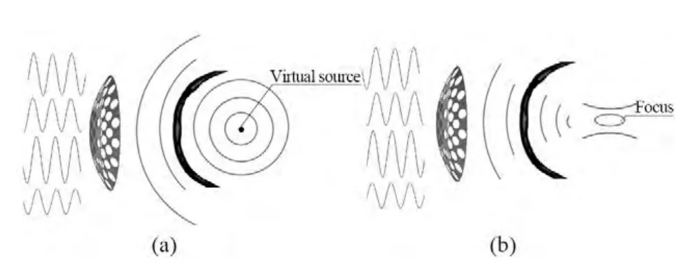
图7时间反转示意图
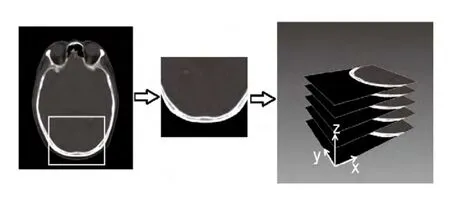
图8颅骨临床CT数据处理过程
相控换能器各阵元的激发电路相对独立,通过分别调控每个阵元的相位和幅值可实现tcFUS聚焦。对于经颅畸变超声相位和幅值失真以及热点(二次高声压旁瓣)等问题均可基于时间反转法进行校正或消除。1996年,Fink等[39]首次将时间反转法用于tcFUS,该方法首先在如图7(a)所示的目标位置设置点声源,超声信号穿过颅骨等介质后由换能器接收信号并将其转换成电信号,对该电信号进行存储和时间反转处理,提取相位信息后加到换能器各自对应的阵元上进行激励[40],可在目标位置处实现自适应聚焦(如图7(b)所示)。同时近年来随着MRI和CT成像技术的进步,为颅骨等组织声学参数的获取提供了可能。1998年,Sun等[38]基于人体颅骨的MRI图像,提取颅骨的轮廓信息,虽然能够确定颅骨的具体位置和厚度,但是不能获得颅骨内部的不均质信息。2001年,Pernot等[41]通过高分辨率颅骨CT图像的亨氏值H求得孔隙率Φ,包括水、颅骨三层典型结构(外层骨密质、内层板障结构),再由孔隙率得出颅骨的声学参数,包括密度ρ、声速c、吸收系数α,其公式如下:

其中,ρwater为水的密度1000kg/m3,ρbone为骨密质的密度2000kg/m3,cwater为水的声速1486m/s,cbone为骨密质的声速3200m/s,αwater为水的吸收系数0.2dB/(m·MHz),αbone为骨密质的吸收系数8dB/(m·MHz),β为常数0.5。
如图8所示为人体头颅CT图像截取和三维重建示意图。通过CT图像三维重建以(2)~(4)式计算颅骨参数,使基于经颅脑肿瘤HIFU治疗数值仿真模型的建立成为可能,为经颅畸变超声校正技术的进一步研究成为可能。
3.1 相位校正法
2001年,Aubry等[42]利用时间反转法对tcFUS相位差进行校正,实验结果表明该方法可实现经颅精确聚焦。2003年,Aubry等[43]基于CT图像获得颅骨声学参数模型,结合时间反转法进行三维时域有限差分仿真,使该相位校正法与CT图像计算颅骨结构及其声学参数相结合,用来预测tcFUS形成的声压场和温度场,仿真结果表明相位校正后焦点位于目标靶区,焦域外无明显旁瓣。
3.2 幅值补偿法
虽然相位校正法可使焦点位于目标靶区,但颅骨的强衰减性、颅骨与周边软组织声阻抗的不匹配等使得聚焦于焦点处的能量损失严重、声场旁瓣较高[44]。2002年,Aubry等[45]对tcFUS进行幅值补偿,结果表明该方法可改善声场聚焦性能、增大焦域能量。2005年,Hynynen等[46]对有无相位或幅值补偿方法的实验进行对比,结果表明幅值补偿法可增大焦域能量并使之均匀化、降低旁瓣声压幅值、改善聚焦质量。2013年,Narumi等[29]基于时间反转的互相关法进行相位校正和幅值补偿,即以某以阵元作为参考阵元,在保持输入能量一致的条件下利用互相关法求得每一阵元的延迟相位和调制幅值(如图9所示),其研究结果表明该幅值补偿法可使能量有效汇聚于目标焦点,但并不能降低热点声压幅值。
3.3 热点消除法
虽然通过相位校正和幅值补偿可使经颅超声精确聚焦在目标靶区,但由于颅骨等介质的非均质性,tcFUS在颅骨内部或颅骨表面易有热点出现。2012年,Nicolas等[47]提出采用重复多次时间反转的方法进行热点消除,即分别在目标靶区和热点位置设置点声源获取相位信号,调整聚焦在热点位置超声信号的相位和幅值后,与聚焦在目标靶区的信号进行线性叠加,以达到降低热点声压幅值的目的。如果热点消除后仍存在热点,可重复进行热点消除,热点消除的终止条件是旁瓣峰值与主瓣峰值的声压比值小于等于0.67[48]。

图9基于互相关法进行相位校正和幅值补偿
4 数值仿真与实验验证
数值仿真是预测tcFUS形成声压场和温度场的有效方法,实验测量是验证仿真方法的有效手段。数值仿真中,非线性声场一般采用Westervelt方程[49,50]或KZK方程[51],线性声场也可采用亥姆霍兹-克希霍夫积分定理[52]等进行计算;对于温度场而言,一般采用Pennes生物热传导方程[53]。验证实验中,一般采用离体颅骨或者活体动物进行HIFU经颅实验。
1998年,Hynynen等[54]进行如图10所示的离体颅骨实验,经水听器测量经颅超声的延迟相位后,加到相控换能器对应阵元上进行激励,实验结果表明该方法可实现相位差的有效校正,使超声准确聚焦于靶区且能量最高。2006年,Marquet等[55]以活体猕猴头颅为研究对象,基于头颅CT扫描数据建立数值仿真模型,通过仿真计算出超声辐照功率及调制相位和幅值后进行活体动物实验,结果表明该方法可实现目标靶区的有效聚焦。2007年,Pernot等[56]选用与人体颅骨参数相近的绵羊进行活体动物实验,在目标靶区插入水听器,基于时间反转法进行经颅超声的相位校正,实验结果表明在目标靶区可产生热损伤。2009年,Marquet等[57]选用活体猴子和离体人颅骨样本进行仿真和实验验证,仿真和实验结果均表明该方法可实现tcFUS有效聚焦,治疗误差在0.7mm范围以内。
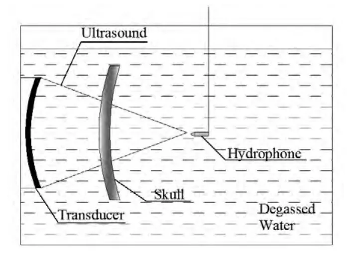
图10离体颅骨实验示意图
5 临床试验及存在的问题
脑肿瘤HIFU治疗具有无创、可重复治疗等优点,受到众多研究者的关注,该技术仍处于研究阶段,到目前为止仅有以色列InSightec公司的ExAblate 3000和4000治疗系统进行过少数病例的临床试验。2010年,McDannold等[58]第一次将HIFU应用于3个恶性胶质瘤患者,其中一位患者选取的最大功率为650W,另两位患者选取最大功率为800W,但此试验最终没有对治疗区域造成热凝固性坏死损伤。2011年,Martind等[59]对丘脑胶质瘤病人进行tcFUS治疗,试验结果表明肿瘤组织完全消融,但是病人五天后死于对侧脑室出血。食品药品监督管理局对此事进行深入调查,但未发现治疗与死因间的因果关系。2012年,Jeanmonod等[60]对神经性疼痛进行tcFUS治疗,治疗结束后发现有一例病人有一处8~10mm出血点。在经颅脑肿瘤HIFU临床治疗过程中,精确聚焦是其关键技术之一,在实现精确聚焦之后,如在高能量下颅骨及其周边组织的热损伤问题[61,62],治疗过程中温度监控及其治疗剂量问题[63],通过焦点后的连续超声波再被颅骨反射及其形成驻波效应[64,65]的影响等尚不清楚。由于这些问题的存在,制约着经颅脑肿瘤HIFU治疗的临床应用。
6 总结
tcFUS脑肿瘤治疗的关键在于使超声能量高度集中在靶区位置以增强病变区域的辐照效果和能量沉积,这既要求超声换能器具有精确的聚焦特性和较高的声强增益,又要尽可能减少对颅骨及头皮等正常组织的损伤。目前,筛选并研制适合不同部位脑肿瘤治疗的相控阵换能器、改进经颅相控阵聚焦超声系统的控制技术,对无创治疗脑肿瘤的治疗效果和临床推广有着重要意义。随着这些关键技术问题的解决,tcFUS脑肿瘤治疗的应用具有广阔前景。
[1] Haar G T, Coussios C. High intensity focused ultrasound: physical principles and devices. International Journal of Hyperthermia, 2007,23(2): 89-104.
[2] Kennedy J E. High-intensity focused ultrasound in the treatment of solid tumours. Nature reviews cancer, 2005, 5(4): 321-327.
[3] White D N, Clark J M, Chesebrough J N,et al.Effect of the skull in degrading the display of echoencephalographic B and C scans. The Journal of the Acoustical Society of America, 1968, 44(5): 1339-1345.
[4] Fry W J, Fry F J, Barnard J W,et al.Ultrasonic lesions in mammalian central nervous system. Science, 1955, 122(3179):1091-1091.
[5] Fry W J, Barnard J W, Fry F J,et al.Ultrasonically produced localized selective lesions in the central nervous system. American Journal of Physical Medicine & Rehabilitation, 1955, 34(3): 413-423.
[6] Fry W J. Intense ultrasound in investigations of the central nervous system. Advances in biological and medical physics, 1957, 6: 281-348.
[7] Fry W J, Fry F. Fundamental neurological research and human neurosurgery using intense ultrasound. IRE Trans Med Electron,1960, 3: 166-181.
[8] Kyriakou A, Neufeld E, Werner B,et al.A review of numerical and experimental compensation techniques for skull-induced phase aberrations in transcranial focused ultrasound. International Journal of Hyperthermia, 2013, 30(1): 36-46.
[9] Martin E, Jeanmonod D, Morel A,et al.High-intensity focused ultrasound for noninvasive functional neurosurgery. Annals of neurology, 2009, 66(6): 858-861.
[10] Lipsman N, Schwartz M L, Huang Y,et al.MR-guided focused ultrasound thalamotomy for essential tremor: a proof-of-concept study. The Lancet Neurology, 2013, 12(5): 462-468.
[11] Dalecki D. Mechanical bioeffects of ultrasound. Annu. Rev. Biomed.Eng., 2004, 6: 229-248.
[12] Humphrey V F. Ultrasound and matter-Physical interactions.Progress in biophysics and molecular biology, 2007, 93(1): 195-211.
[13] Yin X, Hynynen K. A numerical study of transcranial focused ultrasound beam propagation at low frequency. Physics in medicine and biology, 2005, 50(8): 1821-1836.
[14] Fry F J, Barger J E. Acoustical properties of the human skull. The Journal of the Acoustical Society of America, 1978, 63(5): 1576-1590.
[15] 陈亚珠.相控聚焦高强度换能器阵列: 中国, 200410017185.3.2005-01-12.
[16] Ebbini E S, Cain C A. A spherical-section ultrasound phased array applicator for deep localized hyperthermia. Biomedical Engineering,IEEE Transactions on, 1991, 38(7): 634-643.
[17] Marquet F, Boch A L, Pernot M,et al.Non-invasive ultrasonic surgery of the brain in non-human primates. The Journal of the Acoustical Society of America, 2013, 134(2): 1632-1639.
[18] Okita K, Ono K, Takagi S,et al.Numerical simulation of the tissue ablation in high-intensity focused ultrasound therapy with array transducer. International Journal for Numerical Methods in Fluids,2010, 64(10-12): 1395-1411.
[19] Pinton G, Aubry J F, Fink M,et al.Effects of nonlinear ultrasound propagation on high intensity brain therapy. Medical physics, 2011,38(3): 1207-1216.
[20] Sun J, Hynynen K. The potential of transskull ultrasound therapy and surgery using the maximum available skull surface area. The Journal of the Acoustical Society of America, 1999, 105(4): 2519-2527.
[21] Clement G T, White P J, King R L,et al.A magnetic resonance imaging-compatible, large-scale array for trans-skull ultrasound surgery and therapy. Journal of ultrasound in medicine, 2005, 24(8):1117-1125.
[22] http://finance.ifeng.com/usstock/realtime/20090714/935495.shtml[OL]. 2009-07-14.
[23] Chauvet D, Marsac L, Pernot M,et al.Targeting accuracy of transcranial magnetic resonance–guided high-intensity focused ultrasound brain therapy: a fresh cadaver model: Laboratory investigation. Journal of neurosurgery, 2013, 118(5): 1046-1052.
[24] Ji X, Bai J, Shen G,et al.High-intensity focused ultrasound with large scale spherical phased array for the ablation of deep tumors.Journal of Zhejiang University SCIENCE B, 2009, 10(9): 639-647.
[25] Daum D R, Hynynen K. Theoretical design of a spherically sectioned phased array for ultrasound surgery of the liver. European journal of ultrasound, 1999, 9(1): 61-69.
[26] 向军. HIFU多焦点声焦域形态研究.重庆医科大学硕士学位论文.2010.
[27] Clement G T, Sun J, Giesecke T,et al.A hemisphere array for noninvasive ultrasound brain therapy and surgery. Physics in medicine and biology, 2000, 45(12): 3707-3719.
[28] Connor C W, Clement G T, Hynynen K. A unified model for the speed of sound in cranial bone based on genetic algorithm optimization. Physics in medicine and biology, 2002, 47(22): 3925-3944.
[29] Narumi R, Matsuki K, Mitarai S,et al.Focus control aided by numerical simulation in heterogeneous media for high-intensity focused ultrasound treatment. Japanese Journal of Applied Physics,2013, 52(7S): 07HF01.
[30] Raju B I, Hall C S, Seip R. Ultrasound therapy transducers with space-filling non-periodic arrays. Ultrasonics, Ferroelectrics and Frequency Control, IEEE Transactions on, 2011, 58(5): 944-954.
[31] Clement G T, White J, Hynynen K. Investigation of a large-area phased array for focused ultrasound surgery through the skull.Physics in medicine and biology, 2000, 45(4): 1071-1083.
[32] Sharifi H, Soltanian-Zadeh H. New 2D ultrasound phased-array design for hyperthermia cancer therapy. International Society for Optics and Photonics, 2001: 473-482.
[33] Okita K, Ono K, Takagi S,et al.Development of high intensity focused ultrasound simulator for large-scale computing.International Journal for Numerical Methods in Fluids, 2011, 65(1-3): 43-66.
[34] Song J, Hynynen K. Electronically steerable large-scale ultrasound phased-array for noninvasive transcranial therapy. Ultrasonics Symposium, 2008. IUS 2008. IEEE. IEEE, 2008: 447-450.
[35] Pernot M, Aubry J F, Tanter M,et al.High power transcranial beam steering for ultrasonic brain therapy. Physics in medicine and biology, 2003, 48(16): 2577-2589.
[36] Tanter M, Pernot M, Aubry J F,et al.Compensating for bone interfaces and respiratory motion in high-intensity focused ultrasound. International Journal of Hyperthermia, 2007, 23(2): 141-151.
[37] Pernot M, Aubry J F, Tanter M,et al.High power phased array prototype for clinical high intensity focused ultrasound: applications to transcostal and transcranial therapy. Engineering in Medicine and Biology Society, 2007. EMBS 2007. 29th Annual International Conference of the IEEE. IEEE, 2007: 234-237.
[38] Sun J, Hynynen K. Focusing of therapeutic ultrasound through a human skull: a numerical study. The Journal of the Acoustical Society of America, 1998, 104(3): 1705-1715.
[39] Thomas J L, Fink M A. Ultrasonic beam focusing through tissue inhomogeneities with a time reversal mirror: application to transskull therapy. Ultrasonics, Ferroelectrics and Frequency Control, IEEE Transactions on, 1996, 43(6): 1122-1129.
[40] 刘冬冬, 张碧晶. 超声时间反转扫描方法研究. 声学技术, 2011,12(30): 23-24.
[41] Pernot M, Aubry J F, Tanter M,et al.Experimental validation of 3D finite differences simulations of ultrasonic wave propagation through the skull. Ultrasonics Symposium, 2001 IEEE. IEEE, 2001,2: 1547-1550.
[42] Aubry J F, Tanter M, Gerber J,et al.Optimal focusing by spatiotemporal inverse filter. II. Experiments. Application to focusing through absorbing and reverberating media. The Journal of the Acoustical Society of America, 2001, 110(1): 48-58.
[43] Aubry J F, Tanter M, Pernot M,et al.Experimental demonstration of noninvasive transskull adaptive focusing based on prior computed tomography scans. The Journal of the Acoustical Society of America, 2003, 113(1): 84-93.
[44] Tanter M, Thomas J L, Fink M. Focusing and steering through absorbing and aberrating layers: Application to ultrasonic propagation through the skull. The Journal of the Acoustical Society of America, 1998, 103(5): 2403-2410.
[45] Aubry J F, Cassereau D, Tanter M,et al.Skull surface detection algorithm to optimize time reversal focusing through a human skull[C].Ultrasonics Symposium, 2002. Proceedings. 2002 IEEE.IEEE, 2002, 2: 1451-1454.
[46] White J, Clement G T, Hynynen K. Transcranial ultrasound focus reconstruction with phase and amplitude correction. Ultrasonics,IEEE Transactionson Ferroelectrics and Frequency Control, 2005,52(9): 1518-1522.
[47] Leduc N, Okita K, Sugiyama K,et al.Focus control in HIFU therapy assisted by time-reversal simulation with an iterative procedure for hot spot elimination. Journal of Biomechanical Science and Engineering, 2012, 7(1): 43-56.
[48] Song J, Pulkkinen A, Huang Y,et al.Investigation of standingwave formation in a human skull for a clinical prototype of a largeaperture, transcranial MR-guided focused ultrasound (MRgFUS)phased array: an experimental and simulation study. Biomedical Engineering, IEEE Transactions on, 2012, 59(2): 435-444.
[49] Hamiltion M F, Blockstock D T. Nonlinear Acoustics. Boston:Academic Press, 1998.
[50] Bailty M, Khokhlova V, Sapozhnikov O,et al.Physical mechanism of the therapeutic effect of ultrasound (A review). Acoustic physics.2003, 49(4): 369-388.
[51] 孙俊霞. 高强度聚焦超声肿瘤治疗系统的换能器研究和生物效应分析. 上海: 上海交通大学, 2001.
[52] 章琛曦, 张素, 张炤, 等. 相控阵聚焦超声消融肿瘤的建模与仿真.系统仿真学报, 2007, 19(1): 164-167.
[53] Pennes HH. Analysis of tissue and arterial blood temperatures in the resting human forearm. Journal of Applied Physiology, 1948,1: 93-122.
[54] Hynynen K, Jolesz F A. Demonstration of potential noninvasive ultrasound brain therapy through an intact skull. Ultrasound in medicine & biology, 1998, 24(2): 275-283.
[55] Marquet F, Pernot M, Aubry J F,et al.Non-invasive transcranial ultrasound therapy guided by CT-scans. Engineering in Medicine and Biology Society, 2006. EMBS'06. 28th Annual International Conference of the IEEE. IEEE, 2006: 683-687.
[56] Pernot M, Aubry J F, Tanter M,et al.In vivo transcranial brain surgery with an ultrasonic time reversal mirror. Journal of neurosurgery, 2007, 106(6): 1061-1066.
[57] Marquet F, Pernot M, Aubry J F,et al.Non-invasive transcranial ultrasound therapy based on a 3D CT scan: protocol validation and in vitro results. Physics in medicine and biology, 2009, 54(9): 2597.
[58] McDannold N, Clement G, Black P,et al.Transcranial MRI-guided focused ultrasound surgery of brain tumors: Initial fi ndings in three patients. Neurosurgery, 2010, 66(2): 323.
[59] Martin E, Jolesz F A. Noninvasive treatment for brain tumors:Magnetic resonance-guided focused ultrasound surgery. Tumors of the Central Nervous system, Volume 3. Springer Netherlands, 2011: 227-236.
[60] Jeanmonod D, Werner B, Morel A,et al.Transcranial magnetic resonance imaging–guided focused ultrasound: noninvasive central lateral thalamotomy for chronic neuropathic pain. Neurosurgical focus, 2012, 32(1): E1.
[61] Dubinsky T J, Cuevas C, Dighe M K,et al.High-intensity focused ultrasound: current potential and oncologic applications. American journal of roentgenology, 2008, 190(1): 191-199.
[62] Hynynen K. MRI-guided focused ultrasound treatments. Ultrasonics,
2010, 50(2): 221-229.
[63] Hijnen N, Langereis S, Grüll H. Magnetic resonance guided highintensity focused ultrasound for image-guided temperature-induced drug delivery. Advanced drug delivery reviews, 2014, 72: 65-81.
[64] O'Reilly M A, Huang Y, Hynynen K. The impact of standing wave effects on transcranial focused ultrasound disruption of the blood–brain barrier in a rat model. Physics in medicine and biology, 2010,55(18): 5251.
[65] Song J, Pulkkinen A, Huang Y,et al.Investigation of standingwave formation in a human skull for a clinical prototype of a largeaperture, transcranial MR-guided focused ultrasound (MRgFUS)phased array: an experimental and simulation study. Biomedical Engineering, IEEE Transactions on, 2012, 59(2): 435-444.

