
Electrochemical deposition of Mg(OH)2/GO composite flms for corrosion protection of magnesium alloys
2015-02-16 01:44:17FengxiaWuJunLiangWeixueLi
Journal of Magnesium and Alloys 2015年3期
Fengxia Wu,Jun Liang*,Weixue Li
aState Key Laboratory of Solid Lubrication,Lanzhou Institute of Chemical Physics,Chinese Academy of Sciences,Lanzhou 730000,China
bState Key Laboratory of Advanced Processing and Recycling of Non-ferrous Metals,Lanzhou University of Technology,Lanzhou 730050,China
cSchool of Science,Lanzhou University of Technology,Lanzhou 730050,China
Electrochemical deposition of Mg(OH)2/GO composite flms for corrosion protection of magnesium alloys
Fengxia Wua,b,c,Jun Lianga,*,Weixue Lib,c
aState Key Laboratory of Solid Lubrication,Lanzhou Institute of Chemical Physics,Chinese Academy of Sciences,Lanzhou 730000,China
bState Key Laboratory of Advanced Processing and Recycling of Non-ferrous Metals,Lanzhou University of Technology,Lanzhou 730050,China
cSchool of Science,Lanzhou University of Technology,Lanzhou 730050,China
Mg(OH)2/graphene oxide(GO)composite flm was electrochemical deposited on AZ91D magnesium alloys at constant potential.The characteristics of the Mg(OH)2/GO composite flm were investigated by scanning electron microscope(SEM),energy-dispersive X-ray spectrometry(EDS),X-ray diffractometer(XRD)and Raman spectroscopy.It was shown that the faky GO randomly distributed in the composite flm.Compared with the Mg(OH)2flm,the Mg(OH)2/GO composite flm exhibited more uniform and compact structure.Potentiodynamic polarization tests revealed that the Mg(OH)2/GO composite flm could signifcantly improve the corrosion resistance of Mg(OH)2flm with an obvious positive shift of corrosion potential by 0.19 V and a dramatic reduction of corrosion current density by more than one order of magnitude. ©2015 Production and hosting by Elsevier B.V.on behalf of Chongqing University.
Thin flms;Coating;Electrochemical techniques;Corrosion
1.Introduction
Magnesium(Mg)and its alloys have been widely used due to its excellent physical and mechanical properties,such as low density,high strength/weight ratio,high stiffness,mechanical castability and good vibration damping character[1–3]. However,the low corrosion resistance of Mg alloys in common ambient environments due to high electrochemical activity limits its applications,especially in marine environments[4–6]. To reduce the corrosion of Mg alloys,a number of protective treatments have been investigated,such as element alloying and surface flms[1].The latter methods can decrease corrosion rate of Mg alloys by a few orders of magnitude by providing a barrier between the Mg substrate and its environment,which is more effcient compared to alloy development[7].
Graphene oxide(GO),the oxygenated counterpart of one atom thick graphene sheet,has been applied in various biotechnologies,due to its extremely large surface area,ease of chemical functionalization,and good biocompatibility[8].Moreover, GO shows desirable dispersion behavior in aqueous solutions and possesses good mechanical property[8].Consequently, there is growing interest in the scientifc community to develop new and advanced technique for GO on different metal surfaces,keeping in view its exceptional properties to protect them from corroding in harsh environmental conditions.He et al.[9] fabricated uniform GO flms on sintered NdFeB by electrophoretic deposition(EPD).The decrease in corrosion current density and the positive shift in corrosion potential have both demonstrated that GO flms served as a corrosion inhibitor. Park et al.[10]deposited GO onto carbon steel from a GO water suspension by the same EPD method.However,the GO layer did not provide suffcient protection for the steel because the GO flms were not formed densely enough,and the defects on the surface acted as the corrosion initiation sites.
Further,GO/polymer composite flms have also been fabricated by EPD method to effectively protect metal subtracts from NaCl aqueous solution.Singh et al.[11,12]reported the fabrication of a robust graphene reinforced polymeric isocyanate crosslinked with hydroxy functional acrylic adhesive (PIHA)composite flms to prevent copper based structure from oxidation and further corrosion.On the other hand,Zhou et al.[13]and Deng et al.[14]fabricated polypyrrole/graphene oxide (PPy/GO)nanocomposites by a one-step electrochemical deposition method.To our best knowledge,however,there has been no effort to fabricate the GO reinforced inorganic composite flms for improved corrosion protection.
In this paper,we tried to directly deposit GO reinforced Mg(OH)2composite flms on Mg alloy substrate in a Mg2+aqueous solution by adding a good dispersion of GO sheets by constant potential electrochemical deposition method.Such kind of composite flms may have potential application in corrosion protection of biomedical Mg alloy due to the excellent biocompatibility of GO and Mg(OH)2[8,15].In order to compare the characterization of Mg(OH)2/GO composite flms, we also directly deposit Mg(OH)2flms on Mg alloy substrate by same deposition conditions.The structure,composition and corrosion resistance to the Mg alloy substrate of the Mg(OH)2and Mg(OH)2/GO composite flms were investigated.
2.Experimental
2.1.Fabrication of GO,Mg(OH)2flm and Mg(OH)2/GO composite flm
AZ91D Mg alloy was used as the substrate in the present study.The chemical composition(wt.%)of magnesium alloy wereAl 9.1,Zn 0.85,Mn 0.27,Mg balance.All specimens were ground with waterproof abrasive papers and successively cleaned in acetone and distilled water.
The modifed Hummers method was utilized to prepare graphene oxide(GO)as described in the literature[16].In a typical procedure,graphite powder(3 g,325 mesh)was put into a fask containing H2SO4(12 mL),K2S2O8(2.5 g),and P2O5(2.5 g)at 80°C.The mixture was kept at 80°C for 4.5 h using a hot plate.Successively,the mixture was cooled to room temperature and diluted with 0.5 L of H2O and left overnight.And then,the residual acid of the mixture was removed by fltered and washed with H2O using a 0.45µm Millipore flter.The product was dried under ambient condition. This preoxidized graphite was then subjected to oxidation by Hummers’method described as follows.Briefy,pretreated graphite powder was put into cold(0°C)concentrated 120 mL of H2SO4.Then,KMnO4(15 g)was added slowly under stirring.The temperature of the mixture was kept to be below 20°C by cooling.Successively,the mixture was stirred at 35°C for 2 h and then carefully diluted with 250 mL of H2O. After that,the mixture was stirred for 2 h,and an additional 0.7 L of H2O was then added.Shortly,20 mL of 30%H2O2was added to the mixture.The resulting brilliant-yellow mixture was fltered and washed with 10 wt.%HCl aqueous solution to remove metal ions followed by washing repeatedly with H2O to remove the acid until the pH of the fltrate was neutral.The GO slurry was dried in a vacuum oven at 60°C and purifed by dialysis for 1 week.
Electrochemical deposition of the Mg(OH)2flm and GO reinforced Mg(OH)2composite flm on AZ91D Mg alloy were performed using the Autolab PGSTAT302N system.A threeelectrode setup in an undivided cell was used for the electrochemical deposition process,with the as-prepared AZ91D Mg alloy specimens 40 mm×20 mm×5 mm as working electrodes,a graphite rod as the counter electrode,and anAg/AgCl electrode(saturated with KCl)as the reference electrode.The Mg(OH)2flm was deposited using 1 L aqueous solution dissolved 25.6 g Mg(NO3)2·6H2O(analytical purity)as the Mg2+source(0.1 M Mg2+).The aqueous solution with the same concentration of Mg2+with addition of 10 mg well-dispersed GO sheets was used to deposit the GO reinforced Mg(OH)2composite flm.Electrochemical deposition processes were carried out at room temperature(25°C)using applied potentials−1.9 V for 3600 s.After each deposition,the resulting surface was thoroughly rinsed with DI water and dried with a gentle stream of nitrogen gas.
2.2.Characterization of Mg(OH)2flm and Mg(OH)2/GO composite flm
SEM images and EDS were obtained using a JEOL JSM-5600LV scanning electron microscope operated at 20 kV.SEM images of the flms were coated with gold using a thermal evaporator before imaging to minimize charging problems. However,EDS spectra and elemental distribution of the samples were not evaporated gold.XRD patterns were recorded on a Scintag X2 diffractometer(Cu Kα radiation).The accelerating voltage was set at 40 kV with 60 mA current from 5°to 70°.Raman spectra were performed using a Horiba JobinYvon LabRAM-HR800 equipped with a HeNe(532 nm)laser operating at 10%power.Extended scans(10 s)were performed between 100 and 4000 wave numbers with a laser spot size of 1µm×1µm.
The corrosion resistance of the flms was evaluated using potentiodynamic polarization tests on the Autolab PGSTAT302N electrochemicalsystem.A typicalthreeelectrode cell system was used to perform the polarization tests in 3.5wt.%NaCl solution.Working electrode was the electrodeposited specimen.A platinum plate was used as counter electrode.The reference electrode was an Ag/AgCl electrode (saturated with KCl).The NaCl solution was prepared from deionized water with pH of around 6.8±0.2 and the exposed area of the electroplated specimen to the solution was 0.5 cm2. After 30 min of initial delay,potentiodynamic polarization was scanned from−0.35 V with reference to OCP at a sweep rate of 1 mV s−1to a fnal current density of 0.01 mA cm−2.All tests were carried out at room temperature and were performed in triplicate to ensure the reproducibility.
3.Results and discussion
3.1.Electrochemical deposition Mg(OH)2flm and Mg(OH)2/GO composite flm processes
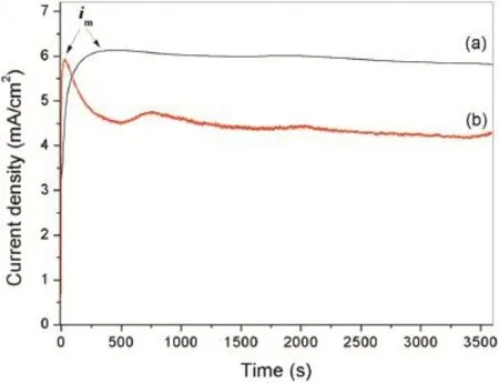
Fig.1.Variation of current density with deposition time in Mg2+nitrate solution(a)without and(b)with GO sheets at the applied potential of−1.9 V.
Fig.1 shows the variation of current density with deposition time of electrochemical deposition process in Mg2+nitrate solutions with and without GO sheets at the applied potential from−1.9 V.In both curves,the current densities increase immediately after application of the potentials,mainly due to doublelayer capacitance charges[17].The maximum current densities (im)shown in thei–tcurves for the Mg2+nitrate solutions with and without GO sheets are read to be about 5.9 and 6.1 mA/cm−2,respectively.After that,the current density of the Mg2+nitrate solution without GO sheets decreased gradually to a stable value.However,the current density of the Mg2+nitrate solution with adding GO sheets sharply decreased after reachingimand then reached to a relatively stable level.It was clear that the current density of the Mg2+nitrate solution with GO sheets is lower than that of the solution without GO sheets during the stable level.The difference of thei–tbehavior can be mainly ascribed to the presence of the GO sheets decreasing the conductivity of the solution.The change of thei–tbehavior would infuence the structure and property characteristics of the resulting flm.
3.2.Composition and microstructure of Mg(OH)2flm and Mg(OH)2/GO composite flm
The surface SEM micrographs of the flm deposited from the Mg2+nitratesolutionswith and without GOsheets are presented in Fig.2.It can be seen from Fig.2a that the flm deposited from the Mg2+nitrate solution(denoted as Mg(OH)2flm)is not uniform and many particles are presented on the surface.These particles,with several micrometers in diameter,cluster together on the surface as shown in Fig.2b.In addition,some cracks and micropores can be observed in the flm.It is believed that the cracks and microspores might be generated by the vigorous hydrogen bubbling occurred at the surface of the specimen during the electrochemical deposition process.These defects, acting as channels that water infltrate into Mg alloys substrate, deteriorate corrosion protection of the flm.The flm deposited from the Mg2+nitrate solution with GO sheets exhibits different surface morphologies.It can be seen from Fig.2c that this flm has more uniform surface and the particles disappeared,though there are still some cracks and micropores in the flm.Instead, some faky substances randomly distribute on the surface of the flm(Fig.2d).The EDS spectrum and elemental distribution thereon of the flm deposited from the Mg2+nitrate solution with GO are displayed in Fig.3.It can be seen that the flm consists of C,O and Mg elements.The C elementary mapping shows that the C element randomly distributes in the flm.The distribution of C element is well consistent with that of the faky substances shown in Fig.2d,suggesting that these substancesmight be the GO sheets embedded into the deposited flm (denoted as Mg(OH)2/GO composite flm).
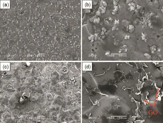
Fig.2.Surface SEM micrograph morphologies of the flm deposited from the Mg2+nitrate solutions(a,b)without and(c,d)with GO sheets on AZ91D alloys.
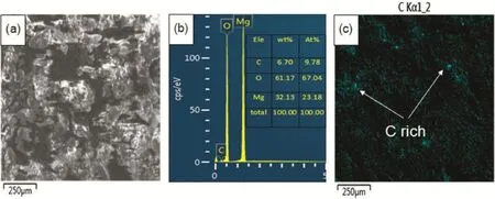
Fig.3.EDS spectrum and elemental distribution thereon of the flm deposited from the Mg2+nitrate solution with GO sheets on AZ91D alloys.
Raman spectroscopy is used to investigate the presence of the GO in the flm deposited from the Mg2+nitrate solution with GO sheets.Fig.4 exhibits the Raman spectra of the flms deposited from the Mg2+nitrate solutions with and without GO as well as the pristine GO sheets.There are no any obvious Raman peaks for the flm deposited from the Mg2+nitrate solution as shown in Fig.4a.Meanwhile,two major peaks at 1330–1360 cm−1and 1590–1600 cm−1are present in Fig.4b and c, which are normally referred to D and G bands[18],respectively.The occurrence of G band is due to the E2gphonon mode of in-plane sp2carbon–carbon double bond stretching motion and the D band is caused by the vibrations of carbon atoms with dangling bonds in plane terminations of disordered graphite [19].The presence of D and G bands on the Raman spectrum of the flm deposited from the Mg2+nitrate solutions with GO confrms that the GO is codeposited with the Mg(OH)2to form a composite flm on AZ91 alloy.
Fig.5 displays the XRD patterns of the flms deposited from the Mg2+nitrate solutions with and without GO.The XRD pattern of GO sheets used in this work is also presented in Fig.5.It is found that the flms deposited from the Mg2+nitrate solutions with and without GO sheets have almost the same XRD patterns(Fig.4a and b).The major diffraction peaks of (001),(101),(102),(110)and(111)in the patterns are ascribed to hexagonal Mg(OH)2(JCPDF fle NO.44–1482),indicating that the flm is composed of Mg(OH)2and the presence of the GO sheets in the Mg2+nitrate solution has no effect on the crystallization characteristics of the Mg(OH)2flm.The diffraction peaks corresponding to GO are not observed in the XRD patterns for the flm deposited from the Mg2+nitrate solutions with GO.The absence of GO diffraction peaks could originate from its low content in the flm.This is consistent with the EDS analysis presented in Fig.3,in which the content of C element is much lower than that of the Mg and O elements.
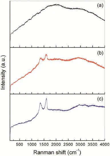
Fig.4.Raman spectra of the flm deposited from the Mg2+nitrate solutions(a) without and(b)with GO sheets onAZ91D alloys as well as(c)the pristine GO sheets.
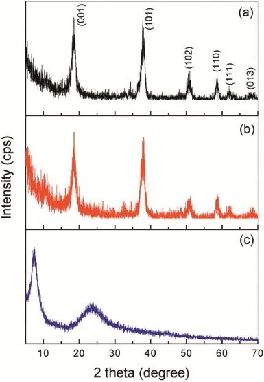
Fig.5.XRD patterns of the flm deposited from the Mg2+nitrate solutions(a) without and(b)with GO sheets onAZ91D alloys as well as(c)the pristine GO sheets.
3.3.Corrosion resistance of the flm
The corrosion protection property of the Mg(OH)2flm and Mg(OH)2/GO composite flm to AZ91D Mg alloys in 3.5 wt.% NaCl solution was evaluated by potentiodynamic polarization tests.Fig.6 displays the polarization curves of Mg(OH)2flm and Mg(OH)2/GO composite flm on the Mg alloys.The polarization curve of bare Mg alloy is also presented in Fig.6 for comparison.The corrosion potential(Ecorr)and corrosion current density(icorr)of the specimens were ftted by usingTafel extrapolation from the polarization curves and the results are listed in Table 1.It can be seen from Fig.6 and Table 1 that both the Mg(OH)2flm and Mg(OH)2/GO composite flm coated Mg alloys have more positiveEcorrand lowericorrthan that of bare Mg alloy.From the polarization curves,it should also be noted that both the Mg(OH)2flm and Mg(OH)2/GO flm coated Mg alloys are characterized by passive regions in the anodic branches.Therefore,the polarization testing results clearly indicate that the Mg(OH)2and Mg(OH)2/GO composite flms could provide effective corrosion protection to the AZ91D substrate in 3.5 wt.% NaCl solution.Furthermore,the Mg(OH)2/GO composite flm registers a remarkable positive shift ofEcorrfrom−1.34 V to−1.15 V and more than one order of magnitude lowericorrthan the Mg(OH)2flm,suggesting that the Mg(OH)2/GO composite flm has better corrosion resistance than the Mg(OH)2flm.The improvement of the corrosion resistance for the Mg(OH)2/GO composite flm may be ascribed to two aspects.Firstly,the GO sheets distributed in the flm improved the stability of the Mg(OH)2flm and decreased the corrosion tendency of theAZ91D Mg alloy by the positive shift of theEcorr.Secondly,though the Mg(OH)2/GO composite flm shows some defects,it possesses more uniform and compact microstructure compared to the Mg(OH)2flm due to the addition of GO in the Mg2+nitrate solution changed thei–tbehavior during the deposition process.The relatively uniform and compact flm on the surface of the AZ91D alloy could effectively reduce the corrosion rate(icorr)of theAZ91D Mg alloy.In addition,the GO sheets in the flm acted as barrier to electron and ion transport between the substrate and the corrosive solution,retarding partially the corrosion of the substrate[20].
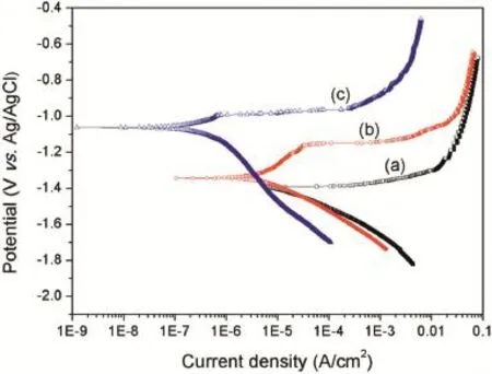
Fig.6.Potentiodynamic polarization behavior of(a)bare Mg alloy,(b) Mg(OH)2and(c)Mg(OH)2/GO coated Mg alloys in 3.5wt.%NaCl solution.
4.Conclusions
Mg(OH)2/GO composite flms were successfully electrochemical deposited onAZ91D Mg alloys at an applied potential of−1.9 V in Mg2+nitrate solution dispersed with GO sheets. The addition of GO sheets into the solution affected the deposition process and the microstructure of the Mg(OH)2flm, resulting in a more dense and uniform surface.Polarization tests in 3.5wt.%NaCl solution revealed that the Mg(OH)2/GO composite flm exhibited better corrosion protection property toAZ91D alloy than the Mg(OH)2flm,which was mainly attributed to the more dense structure of the Mg(OH)2/GO composite flm and the barrier effect of GO sheets embedded in the flm.
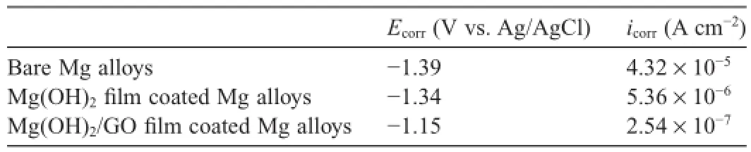
Table 1Corrosion potentials and current densities derived from the polarization tests of the samples.
Acknowledgments
The fnancial support from the“Hundred Talents Program”of Chinese Academy of Sciences(J.Liang)is gratefully acknowledged.
[1]X.B.Chen,X.Zhou,T.B.Abbott,M.A.Easton,N.Birbilis,Surf.Coat. Technol.217(2013)147–155.
[2]R.Gao,Q.Liu,J.Wang,X.Zhang,W.Yang,J.Liu,et al.,Chem.Eng.J. 241(2014)352–359.
[3]R.Zeng,K.U.Kainer,C.Blawert,W.Dietzel,J.Alloys Compd.509 (2011)4462–4469.
[4]L.Wang,T.Shinohara,B.P.Zhang,J.Solid State Electr.14(2010) 1897–1907.
[5]J.Chen,Y.Song,D.Shan,E.-H.Han,Corros.Sci.74(2013)130–138.
[6]G.Galicia,N.Pébère,B.Tribollet,V.Vivier,Corros.Sci.51(2009) 1789–1794.
[7]G.J.X.Cui,E.Liu,M.Ding,Q.Li,F.Wang,Mater.Corros.63(2012) 215–222.
[8]M.Li,Q.Liu,Z.Jia,X.Xu,Y.Cheng,Y.Zheng,et al.,Carbon 67(2014) 185–197.
[9]W.He,L.Zhu,H.Chen,H.Nan,W.Li,H.Liu,et al.,Appl.Surf.Sci.279 (2013)416–423.
[10]J.H.Park,J.M.Park,Surf.Coat.Technol.254(2014)167–174.
[11]B.P.Singh,S.Nayak,K.K.Nanda,B.K.Jena,S.Bhattacharjee,L.Besra, Carbon 61(2013)47–56.
[12]B.P.Singh,B.K.Jena,S.Bhattacharjee,L.Besra,Surf.Coat.Technol.232 (2013)475–481.
[13]H.Zhou,G.Han,Y.Xiao,Y.Chang,H.J.Zhai,J.Power Sources 263 (2014)259–267.
[14]M.Deng,X.Yang,M.Silke,W.Qiu,M.Xu,G.Borghs,et al.,Sensor. Actuat.B-Chem.158(2011)176–184.
[15]P.Tian,X.Y.Liu,Regener.Biomater.2(2015)135–151.
[16]X.Yan,J.Chen,J.Yang,Q.Xue,P.Miele,ACS Appl.Mater.Inter.2 (2010)2521–2529.
[17]V.N.H.Randriamahazaka,C.Chevrot,J.Electroanal.Chem.472(1999) 103–111.
[18]L.M.Malard,M.A.Pimenta,G.Dresselhaus,M.S.Dresselhaus,Phys. Rep.473(2009)51–87.
[19]M.Veerapandian,H.Y.Kim,Y.T.Seo,K.N.Lee,K.Yun,M.H.Lee, Mater.Res.Bull.49(2014)593–600.
[20]J.Liu,L.Hua,S.Li,M.Yu,Appl.Surf.Sci.327(2015)241–245.
Received 16 March 2015;revised 5 August 2015;accepted 25 August 2015 Available online 1 October 2015
*Corresponding author.State Key Laboratory of Solid Lubrication,Lanzhou Institute of Chemical Physics,ChineseAcademy of Sciences,Lanzhou 730000, China.Tel.:+86 931 4968381;fax:+86 931 4968163.
E-mail address:jliang@licp.cas.cn(J.Liang).
http://dx.doi.org/10.1016/j.jma.2015.08.004
2213-9567/©2015 Production and hosting by Elsevier B.V.on behalf of Chongqing University.
 Journal of Magnesium and Alloys2015年3期
- Journal of Magnesium and Alloys的其它文章
- GUIDE FOR AUTHORS
- Infuence of sulfate ion concentration and pH on the corrosion of Mg-Al-Zn-Mn(GA9)magnesium alloy
- Research of growth mechanism of ceramic coatings fabricated by micro-arc oxidation on magnesium alloys at high current mode
- Infuence of solution treatment on microstructure,mechanical and corrosion properties of Mg-4Zn alloy
- Effect of experimental parameters on the micro hardness of plasma sprayed alumina coatings on AZ31B magnesium alloy
- Effect of temperature and strain rate on compressive response of extruded magnesium nano-composite