Optimization design of foundation excavation for Xiluodu super-high arch dam in China
Optimization design of foundation excavation for Xiluodu super-high arch dam in China
Qixiang Fan,Shaowu Zhou*,Ning Yang
China Three Gorges Corporation,Beijing 100038,China
A R T I C L E I N F O
Article history:
Received 30 January 2015
Received in revised form
27 February 2015
Accepted 1 March 2015
Available online 18 March 2015
Super-high arch dam
Foundation surface
Optimization design
Stability analysis
With better understanding of the quality and physico-mechanical properties of rocks of dam foundation, and the physico-mechanical properties and structure design of arch dam in association with the foundation excavation of Xiluodu arch dam,the excavation optimization design was proposed for the foundation surface on the basis of feasibility study.Common analysis and numerical analysis results demonstrated the feasibility of using the weakly weathered rocks III1and III2as the foundation surface of super-high arch dam.In view of changes in the geological conditions at the dam foundation along the riverbed direction,the design of extending foundation surface excavation area and using consolidating grouting and optimizing structure of dam bottom was introduced,allowing for harmonization of the arch dam and foundation.Three-dimensional(3D)geomechanics model test and f nite element analysis results indicated that the dam body and foundation have good overload stability and high bearing capacity. The monitoring data showed that the behaviors of dam and foundation correspond with the designed patterns in the construction period and the initial operation period.
©2015 Institute of Rock and Soil Mechanics,Chinese Academy of Sciences.Production and hosting by Elsevier B.V.All rights reserved.
1.Introduction
As is known,arch dam basically receives forces through both the dam body and the foundation.As the foundation of an arch dam, the rock mass has to bear notonly the deadweight of the upper arch dam,but also the external loads such as water pressures and silt loads,ensuring the stability of itself and the safety of the whole arch dam(Li et al.,2004;Wang et al.,2010).A super-high arch dam over 200 m bears signi f cantly large external loads,for which a matching dam foundation is desirable.For example,hydraulic thrust of Xiluodu super-high arc dam is estimated to be more than 140×106kN(HCEC,2005).However,it is always very dif f cult to accurately evaluate the complicated hydrogeological and other conditions of a natural dam site due to the limitations in geological survey,especially the sites on the riverbed and valley f oor in a gorge area.In a common sense,the foundation surface excavation is a process of dynamic adjustment,which should adapt to the dynamic adjustment of the dam body shape.For an arch dam over 200 m,the foundation surface excavation will be generally 6-12 months delayed from onset of a project.Therefore,the optimization design for foundation excavation of super-high arch dam is critically important.
In China,the rock mass at a dam site can be roughly classi f ed as completely weathered zone,intensively weathered zone,and weakly weathered zone and slightly weathered to fresh zone,from the outside to the inside.Obviously,the f rst two categories cannot be used as the rock foundation of a high arch dam,and thus must be excavated.The weakly weathered to fresh rocks can be used directly as the foundation surface of a high arch dam.Generally,the deeper foundation means higher integrality of the foundation rocks,thus it can bear larger capacity in terms of global safety. However,the foundation excavation and cast-in-place concrete amount will be signi f cantly increased,leading to a much longer construction period and larger additional investment.On the other hand,the external loads on the dam body and dam abutment will increase with increasing depth of dam abutment and arch span,and those problems such as high slope stability will arise.Therefore,the process of optimization design for the foundation of a super-high arch dam is focusing on the feasibility and utilization degree of weakly weathered rock mass as dam foundation with increasing understanding of the geological conditions,and thus to establish a suitable evaluation system for safety purpose of arch dam body and foundation(Wang,2007;Wang and Lin,2008).
This paper introduces the optimization concepts of the foundation interface design of the Xiluodu super-high arch dam,the structure optimization design and foundation treatment measures in terms of variations in basic geological conditions in the riverbed region.The f nite element analyses and three-dimensional(3D)geological model test results indicate that when using the weakly weathered rocks III1and III2as the foundation surface of the riverbed dam,the structure optimization at the bottom of the riverbed dam section and the foundation treatment measures adopted can meet the requirements of the overall stability of the dam and foundation,which is also veri f ed by the monitoring data recorded in the construction period and the initial impoundment and operation periods.
2.Understanding and optimization principles of super-high arch dam foundation surface
2.1.Understanding of super-high arch dam foundation surface
According to China’s standards(SL282-2003,2003;DL/T5436-2006,2007),the base rocks in the fresh to slightly weathered zone or the lower part of the weakly weathered zone can be used as the foundation surface for an arch dam,and a special study must be conducted when necessary.In the arch dam design,the degree of rock mass weathering is always used to determine the depth of dam foundation excavation,without concrete control standards for the modulus of deformation.While in other countries and/or regions,more emphases are focused on the effect of foundation reinforcement on the dam body for the technical and economic purposes.Only when the reinforcement measures fail to achieve the desired effect,the entire rock area above the foundation surface will be removed(DIBR,1977;SNiP 2.06.06-85,1985;Zhu,1988). Some arch dams are built on foundation with very low deformation modulus.For example,the Vajont arch dam is 262 m high,with a foundation deformation modulus of 7.5-16 GPa.Another case is the 237 m high Mauvoisin dam,which has a foundation deformation modulus of 4 GPa approximately.
In China,as the understanding of high arch dam is increased and various engineering experiences are obtained,more and more high arch dams begin to use weakly weathered rocks(III1or III2)as foundation surface,and the desirable foundation reinforcement measures are employed to meet the requirement of safe engineering operation,such as the Ertan arch dam,of which the indicators of foundation surface rocks are shown in Table 1(CHIDI, 2000).This is also re f ected in the revised arch dam design standards(SL282-2003,2003;DL/T5436-2006,2007).
2.2.Optimization principles and steps of super-high arch dam foundation surface
For the design of general high arch dam,using weakly weathered rocks for some parts of the dam foundation surface is generally acceptable,which can be veri f ed by the common stress analysis method,calibrated by foundation anti-sliding stability analysis and foundation reinforcement methods(Wang,2007;Wang and Lin, 2008).But for super-high arch dams built in remote mountainous and gorge areas and/or high seismic intensity areas,the geological survey for the foundation of riverbed dam section may be insuf f cient in the feasibility study stage in comparison to the technical construction stage.Due to the possible drawbacks in geological survey and technical measures,insuf f cient analysis will be induced,resulting in an unreasonable design.At the same time, the weakly weathered rocks may have a certain degree of effect on the arch dam stability and safety,due to the slightly poor properties and weaker physico-mechanical behaviors.Thus the rock mass properties,structural safety of arch dam,anti-sliding stability,and overall arch dam safety should be combined to evaluate how to utilize the weakly weathered rocks,especially for the construction of a 300 m super-high arch dam.
Referring to the foundation excavation process of Xiluodu arch dam,it is suggested that the feasibility is desirable that how to use the rocks III1and III2as the foundation surface in order to optimize the design of super-high arch dam foundation,for the purposes of safety and reliability.Detailed steps are described as follows:

Table 1Rock mass classi f cation and basic characteristics of Ertan arch dam foundation.
(1)Collect data of site-speci f c hydrogeological conditions in the dam site,evaluate the quality of rock mass,and determine the rock quality grading and mechanical parameters of rock mass.
(2)Conduct a preliminarily study on the foundation treatment measures,evaluate the effect of consolidation grouting on the physico-mechanical properties of rock mass,and select the values of foundation rock mass parameters,such as foundation deformation modulus after consolidating grouting is used.
(3)Use the engineering analogy method to analyze the feasibility of foundation optimization,and propose 2-3 candidate foundation surfaces for optimization design of arch dam.
(4)Preliminarily evaluate the feasibility of foundation optimization through commonly used safety analysis methods,such as static stress and dynamic stress method,arch-cantilever method (ACM),stress-displacement analysis method,and anti-sliding stability analysis method.
(5)Evaluate the stability of dam body and foundation after optimization of foundation surface through numerical analysis(e.g. f nite element method)and 3D geomechanics model test,and further verify the reasonability of optimization excavation of foundation surface.
(6)Determine the optimization design scheme in terms of comprehensive analysis and comparison.
(7)Qualitatively evaluate the quality of foundation rock surface at the excavation stage;at the same time,optimize and adjust the foundation treatment measures,with special focus on the geological defects,inter-laminar and intra-formational dislocation belt,according to the site-speci f c geological conditions.
(8)Optimize the design of dam structure at the riverbed dam section,and increase its rigidity adapted to the foundation deformation;use the 3D nonlinear f nite element method or geomechanics model test to evaluate the stability and safety of dam foundation with optimized arch dam structure.
(9)Verify the reasonability of excavation optimization method of super-high arch dam foundation by using monitoring data and the feedback result of arch dam in the construction and(initial) operation periods.
3.Optimization design of foundation excavation of Xiluodu arch dam
3.1.Analysis of the infuential factors on foundation surface selection
The watercourse of Xiluodu dam site is characterized by huge mountains,abrupt slopes,and complete landform on both banks, but with no deep trenches.The valley cross-section is in a narrow U-shape,and the valley width ratio is about 2.0.The angle of theleft-bank valley slope is 40°-75°,and the right-bank valley slope is 55°-75°,steep in the upper part and gentle in the lower part.The foundation surface selection is not governed by the landform,and Fig.1 shows the topography of Xiluodu dam site.
Base rocks of the dam site are composed of Emeishan basalt of the Upper Permian System,characterized by hard rock mass,high strength,massive structure,and complete to relatively complete blocks.Rock mass in the dam area is classi f ed into f ve categories and seven sub-categories in terms of comprehensive quality. Table 2 lists the physico-mechanical parameters.The structural surface of weak steep angles controls the dam foundation deformation and/or sliding of dam abutment anti-force body,which is not developed with hard to relatively hard rock mass in terms of suf f cient strength.The rocks IV and V with poor integrity and cataclastic structure are weakly weathered unloaded rock mass, which are not suitable for the target foundation.Whilst the rocks I and II characterized with suf f cient strength,and rock mass III1characterized with deformation modulus of 10-12 GPa and mediate anti-deformation capacity,can be used as the dam foundation.Rocks III2at some sections can also be used after being reinforced.

Fig.1.Topography of Xiluodu dam site.
3.2.Optimization design of foundation based feasibility study stage excavation
3.2.1.Optimization design of foundation excavation
The selection of arch dam foundation and determination of excavation depth have major effects on dam safety,work amount, construction period and investment(Liu,1996).At the feasibility study stage,the riverbed dam foundation of Xiluodu arch dam was placed at the elevation of 332 m,dominated by weakly weathered to fresh rock mass II.The weakly weathered rock mass III1of lower section was only used when reaching the upper elevation.With further understanding rock quality and mechanical properties of the arch dam foundation associated with the mechanical properties and structure design of arch dam,the design of arch dam foundation was optimized by referring to the established engineering experiences,in order to minimize the arch abutment depth and use the rocks III1 and III2 on the premise of the safety of arch dam foundation.
(1)Riverbed foundation
According to the supplementary results of geological survey,the rock mass on riverbed is considered to be good quality globally, with a small amount of treatment work for dam foundation(see Fig.2).After detailed analysis,the elevation of 332 m was used as the arch dam riverbed foundation in the optimization and comparative schemes,which was raised to 340 m at some places on both sides.Partial intra-formational dislocation belts under the foundation surface and developed weak inter-layers were reinforced;and partial rock mass was removed and concrete was back f lled at some places.Table 3 lists the horizontal depth of the downstream arch abutment of the riverbed foundation for three kinds of foundation surfaces.
(2)Foundations on both banks
For the feasibility study scheme,the dam foundation mainly was composed of the slightly weathered to fresh rocks II;whilst weakly weathered rock mass III1was used only at some places at the elevation of over 560 m.
For the optimization scheme,the dam foundation was moved slightly outside to reduce the depth of arch abutment,with weakly weathered rock mass III1as foundation surface,and rock mass III2as foundation surface for some places at the elevation of over 560 m on the left and right banks.
For the comparative scheme,on the basis of the optimization scheme,the foundation was further adjusted slightly to reduce the depth,and increase the exposure range of rock mass III2.Fig.3 displays the depth of arch abutment of three kinds of foundation surfaces,and Table 4 lists the rock mass quality classi f cation.
(3)Comprehensive comparative analysis of various schemes
(i)Rock formation analysis
Feasibility study scheme:on the foundation surface,the area of rocks II accounted for more than 69%,rocks III1accounted for 30% approximately;rocks III2were only exposed at the downstream side at the elevation of 610 m of the left bank.From the downstream vertical view of the arch abutment,except for the elevation of over 520 m and elevation of 400 m where weakly weathered rockmass III1was used,the arch abutment was basically placed on the slightly weathered to fresh rock mass II on the left bank.

Table 2Comprehensive rock mass quality classi f cation and mechanical parameters in the dam area.
Comparative scheme:the area of rock mass II accounted for 21.22%,rock class III1for 59.35%,rock mass III2for 15.3%;rock mass IV1was only exposed at some places at the elevation of 400-410 m on the left bank and near the elevation of 420 m on the right bank, accounting for 4.13%.
Optimization scheme:compared with the comparative scheme, around 2%rocks II and III1were increased,rock mass III2decreased roughly by 3%,rock mass IV1decreased by 1.5%.The quality of arch dam foundation rock mass in the optimization scheme was better than that in the comparative scheme,and slightly worse than that in the feasibility study scheme(see Table 4 and Fig.4).
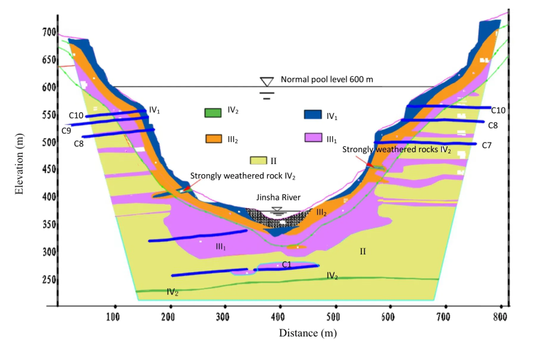
Fig.2.Engineering geological pro f le of the Xiluodu arc dam.

Table 3Horizontal depth of downstream arch abutment of riverbed foundation arch support (unit:m).
(ii)Analysis of foundation depth
Feasibility study scheme:the depth of arch dam foundation on the left and right banks was relatively large,with an average of 43.6 m and 49.7 m,respectively,but favorable formation conditions of Xiluodu dam site were not fully used.
Comparative scheme:compared with the feasibility study scheme,the average depth was signi f cantly decreased,about 16 m and 14 m on the left and the right banks,respectively,especially at the lower middle elevation.The arch abutment below the elevation of 560 m was basically placed on the lower segment weakly weathered rocks III1,and upper segment weakly weathered rocks III2was used at the elevation over 560 m.The foundation surface shape was relatively smooth.
Optimization scheme:the left-bank arch abutment depth was about 3 m deeper than that in the comparative scheme.The rightbank one was basically equal to that in the comparative scheme.For the abutment of the left-bank arch at elevation of 440 m,it was 4.4 m deeper than that in the comparative scheme,thus more rock mass III1and less rock mass III2can be used in order to control the dam foundation deformation associated with enough bearing capacity.The right-bank arch abutment depth within the middle elevation of 560-440 m was increased slightly(see Table 5).
3.2.2.Design of arch dam shape
The ACM was used to calculate the dam stress.Five line shapes (parabola,uni f ed quadratic curve,3-center circle,log-spiral,and ellipse)were compared and analyzed in consideration of engineering geology,design,construction,engineering experience and other factors.It is reported that parabola was chosen as the line type of Xiluodu arch dam as it is better adaptable to U-shaped valley(HCEC,2005).Table 6 gives the dam characteristic parameters for three schemes.
Compared with the feasibility study scheme,the arc length of arch dam vault center line and the arch dam thickness in the optimization scheme(see Fig.5)were signi f cantly decreased,but the arc length of center line and the upstream overhang degree were increased slightly,and other shape parameters were basically the same.Partial adjustment of the arch abutment position of foundation almost had no effect on the design of arch dam shape. The dam foundation excavation was 1.61 million m3less and the dam concrete amount was 1.10 million m3less in the optimization scheme than those in the feasibility study scheme.

Fig.3.Arch abutment depth of three kinds of foundation surfaces.(a)Downstream vertical view of arch abutment depth for three kinds of foundation surfaces.(b)Horizontal sliced view of arch ring for three kinds of foundation surfaces at elevation of 440 m.

Table 4Dam foundation rock mass quality classi f cation of 3 kinds of foundation surfaces.
3.2.3.Safety evaluation and analysis
With the basic load combinations,the calculated results indicate similar stress distribution of dam in the three schemes.The dam face was basically in a condition of compression state,meeting the stress control standards,i.e.the maximum tensile stress should be not larger than 1.2 MPa,the allowable compressive stress is not larger than 9.0 MPa,and safety coef f cient of concrete strength under compression is 4.0.In the optimization scheme,the maximum compressive stress of the upstream dam surface was 7.56 MPa,and that of the downstream dam face is 8.66 MPa.Themaximum principal tensile stress of the upstream dam face was 1.13 MPa,and that of the downstream dam face is 1.04 MPa.At the same time,analysis ofdeformation modulus sensitivity ofhost rocks (±20%deformation modulus)shows that the changes in the foundation deformation modulus had no signi f cant effect on the dam stress,and the foundation adaptability was good in each scheme.

Fig.4.Foundation rock mass quality classi f cation in optimization and comparative schemes.
Three kinds of foundation surfaces show a slight difference in the analysis results of anti-sliding stability of dam abutment.Both the factors of safety under pure friction and shear friction conditions basically meet the design control standards.Table 7 presents the factors of safety of anti-sliding dam abutment in the optimization scheme.
3D nonlinear f nite element analysis and 3D geomechanics model test results(Zhou et al.,2004,2006)show that the foundation optimization will not cause abnormality of the dam stress variation.The arch dam stress(see Table 8),displacement distribution,overall safety for 3 kinds of foundation surfaces were quite promising.Meanwhile the overload analysis shows that the global dam structure under normal load combinations was in a state of elastic working condition.No yield and cracking damage appeared on both the upstream and downstream dam faces.This was mostly bene f tted from the symmetrical U-shaped valley of Xiluodu dam site.Table 9 presents the relevant crack initiation overload coef f cientK1,nonlinear deformation load coef f cientK2, and ultimate overload coef f cient before overall instabilityK3of 3 kinds of foundation surfaces.It can be seen that the dam overload capacity in the optimization scheme was equal to that in the feasibility study scheme,and better than that in the comparativescheme,indicating a strong relation between the overload capacity and the quality of foundation rock mass.

Table 5Comparison of horizontal depth of downstream arch abutment for 3 kinds of foundation surfaces.

Table 6Parameters of parabola-shaped double-curvature arch dam.

Fig.5.Design of arch dam shape in optimization scheme.

Table 7Factors of safety of anti-sliding dam abutment in the optimization scheme.
In general,3 kinds of foundation surfaces could all meet the requirements of arch dam design for foundation surface,indicating a good adaptive capacity of arch dam to the changes in the dam foundation deformation modulus.In terms of overload capacity, both the feasibility and optimization schemes can meet the design requirements,but the comparative scheme is slightly defective.The optimization scheme could keep the elevation of dam foundation on the riverbed unchanged,with two banks being moved outward appropriately for engineering safety and signi f cant economic bene f ts purposes.

Table 8Arch dam stress distribution value for 3 kinds of foundation surfaces(3D nonlinear f nite element).

Table 9Arch dam foundation overload coef f cient under 3 kinds of foundation surfaces.
3.3.Optimization design of dam riverbed foundation structure
3.3.1.Global enlargement of excavation of riverbed dam foundation
As the excavation continued,replacement excavation was conducted for geologicaldefects(8 areas on the left bank and 9 areas on the right bank)of the inter-laminar and intra-formation dislocation band and intensively weathered inter-layers that were developed in the basalt rocks at the elevations of 610-500 m,500-400 m and below 400 m,as well as the weakly weathered rocks III2and weak unloaded rocks IV exposed to the foundation surface(Wang et al., 2007a,b,c;2008;Yang et al.,2007a,b).Figs.6 and 7 illustrate the overall arrangement and cross-section of foundation replacement, respectively.After replacement excavation,the foundation at the elevation of 560-610 mwas dominated by rocks II and III1,some by rocks III2.The abrupt-slope dam section foundation at the elevation of 560-400 m was dominated by rocks II and III1.Rocks III2accounted for 5.3%on the left bank,and only 0.8%on the right bank; whilst rocks III1accounted for more than 90%on the gentle-slope dam section foundation at the elevation of 400-328 m,meeting the requirements of foundation rock mass quality.
Additional geological survey of riverbed dam section reveals that the rocks were strongly weathered and the structure of rock mass was not uniformly distributed in the riverbed sections and the gentle-slope dam sections on both banks below the elevation of 400 m,where the disturbed belt was developed in association with gentle slope attitude,especially in the inter-layer along the dislocation belt.Despite that rocks III1were of a large portion,rocks III2and weathered inter-layers in the zone were widely distributed. Given that rock mass in the riverbed dam section is the key of foundation deformation,the riverbed dam foundation had to be raised from the elevation of 340-332 m to 328-324.5 m through one-step global enlargement of excavation,in order to ensure the long-term safe operation of the arch dam.Therefore,the number of the riverbed dam sections of foundation was increased from 3(dam sections 15-17)to 6(dam sections 14-19).Fig.8 shows the overall view of foundation surface of Xiluodu arch dam and Fig.9 showsthe overall view of riverbed foundation surface after the enlargement of excavation of riverbed dam foundation.

Fig.6.Overall arrangement of foundation replacement.
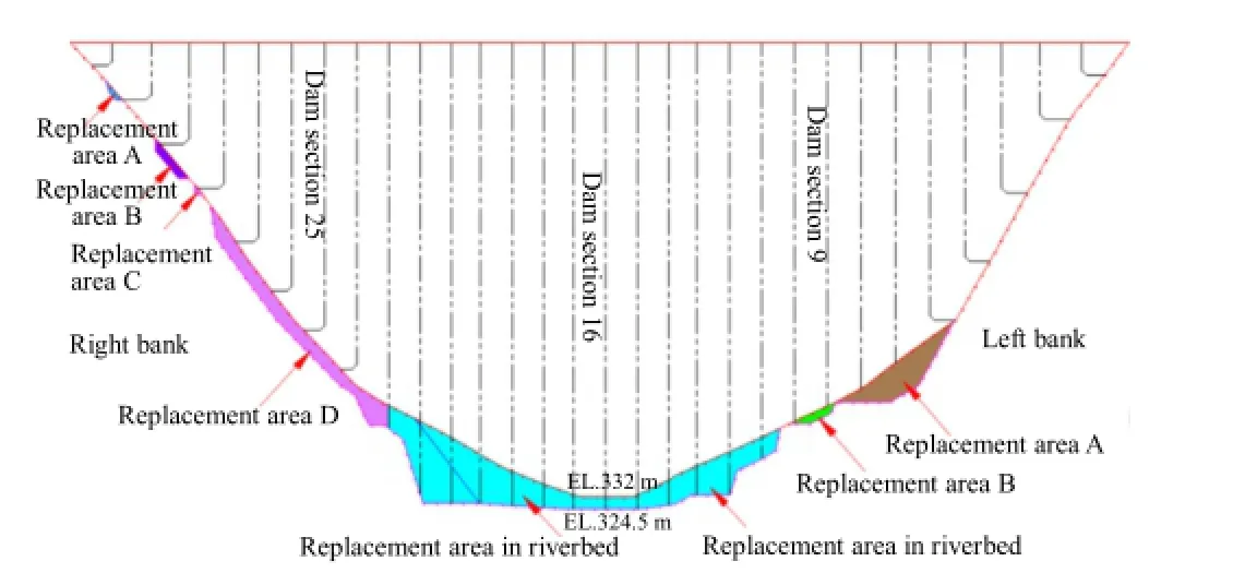
Fig.7.Typical cross-sectional view of foundation replacement.
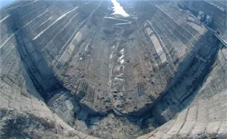
Fig.8.Overall view of foundation surface of Xiluodu arch dam(1:2000).
Global enlargement of excavation(HCEC,2005;Wang and Yang, 2009;Fan etal.,2012;Lu etal.,2013)means thatallrocks IV1and III2are completely removed at the foundation elevation over 324.5 m, the inter-laminar and intra-formation dislocation band and the intensively weathered inter-layers are partially replaced through groove carving.All of the replacement excavation is included in the excavation of the dam foundation in order to reduce the effect of secondary excavation of replacement on the construction progress. At the same time,the downstream replacement excavation areas of geological defects should be enlarged adequately to the banks and lower reaches,which are basically 5-10 m in length.This can reduce the adverse effect of sudden change in the geometrical shape of replaced foundation surface on the dam structure.
After the global enlargement of excavation,dam foundation rocks III1shared a larger percentage of 86%,and rocks III2shared 14.1%.Rocks III2inside the dam foundation were distributed in an intercalated and lenticular shape,in poor continuity spatially.Rocks III2distributed on the foundation surface were removed through groove carving and foundation cleaning.The quality of rock mass can meet the foundation requirements in a global sense(Wang and Yang,2009).Fig.10 displays the overall view of foundation rock mass quality before and after groove carving.
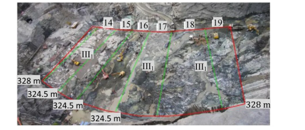
Fig.9.Overall view of riverbed foundation surface after global enlargement of excavation of riverbed dam foundation(1:1000).The numbers 14-19 are the sections.
3.3.2.Optimization design of riverbed dam bottom section
Sonic wave test data after excavation show that the rocks under the foundation surface were mostly weakly weathered to slightly weathered rocks III1.The rock mass at shallow depth of 1-6 m was inninmorite,with average wave velocityVP>4600 m/s,characterized by high rock strength and poor uniformity.Rocks within the depth of 20 m under the foundation surface were rock mass III2(about 15%),which were mainly affected by the intersection of intra-formational belts with gentle inclination.The wave velocity isVP=2500-4000 m/s with gentle spatial distribution and extension length basically of 10-30 m.The dislocation interfaces were dominated by angular gravels,with little rock debris and no mud. Given that the inter-laminar and intra-formation dislocation bands distributed in the rock mass of the riverbed dam section were roughly perpendicular to the load of arch dam beam,the key parts for foundation deformation treatment,it is desirable to improve the rocks and foundation rigidity by grouting methods.At the same time,the design of bottom structure should be optimized,and the stressed area of the foundation was enlarged so that the foundation deformation and stability requirements could be met(Wang and Yang,2009).For this purpose,optimization design was conducted for the arch dam foundation structure on the basis of“global enlargement of excavation”concept,with comprehensive treatment measures employed such as global continuous pouring, consolidating grouting,revetment of slope and toe protection, expansion of overall foundation structure,etc.(Wang and Yang, 2009;Wang et al.,2010;Fan et al.,2012;Lu et al.,2013).

Fig.10.Dam foundation rock mass quality before and after groove carving of riverbed section at elevation of 328-324.5 m.(a)Before groove carving.(b)After groove carving.

Fig.11.Joints of foundation replacement area in riverbed dam section.
Global continuous pouring was f rst to use the cast-in-place concrete of the same grade as used in dam at the replacement area below the elevation of 374 m on the left bank and 376 m on the right bank until the riverbed elevation of 324.5 m(except for the sections C3 and C4 using groove carving method)was reached,in combination with the dam concrete.The partings between replacement areas were the transverse joints of arch dam expanding naturally,which could reduce the negative effect of concrete replacement on the construction progress.Then,the backf lled concrete in the extension of excavation region in the downstream dam toe area was used as the dam toe protection,so that it can be cast associated with the dam concrete.Fig.11 shows the structure joints of replacement areas.
“Consolidating grouting”was proposed to use grouting to consolidate the rocks below the elevation of 324.5 m,especially the rocks III2(15%)within 20 m under the foundation surface.This can improve the foundation integrity and thus control the dam foundation deformation.The f rst step was to increase the depth of grouting hole.The second was using intensive grouting;the third was to adjust the grouting pressure and the new grouting technology.Thus the grouting water-cement ratio was optimized and grinding f ne cement was used.The fourth was to apply anchor piles(3φ32 mm)inside the grouting holes to further improve the integrity of foundation and the dam.
“Revetment of slope and toe protection”was to apply revetment to upstream slope surfaces and toe protection to downstream excavation slope surfaces,respectively.The application of downstream slope toe protection could improve the high stressed distribution state in the dam toe area.The application of upstream slope revetment could prevent any possible cracks propagating toward the dam toe when the upstream contact surface of arch dam was in a tensile state after impoundment.
“Expansion of overall foundation structure”was used for the comparison purpose of the two schemes,i.e.the schemes of“expansion of overall foundation structure”and“cushion for separate foundation abutment”,in terms of structural safety and quality control in construction period.The analysis results obtained from the“expansion of overall foundation structure”scheme show that the dam displacement and stress in the construction and operation periods can meet the design requirements.The overload factor of safety was greater than those in the feasibility study and optimization schemes.Thus,this scheme was f nally adopted.The crack initiation load of upstream dam toe wasP1=(2-2.5)P0(P0is the normal load combination,deadweight of dam+upstream normal water level+corresponding downstream water level+silt pressure+temperature decrease)withK1=2-2.5,the nonlinear deformation load was(5-6)P0withK2=5-6,and the ultimate load wasP3=(9-9.5)P0withK3=9-9.5.
3.3.3.Foundation reinforcement measures for Xiluodu arch dam
The complicated joint loading features of super-high arch dam determine that the arch dam foundation must have suf f ciently global integrity,stability and impermeability,and the rocks in the dam spandrel must be stable(ASCE,1974;Lin et al.,2011).To meet these requirements,the foundation reinforcement measures such as consolidating grouting,curtain grouting,foundation drainage, and anchor cable of dam toe were used for Xiluodu arch dam at the construction stage,in combination with the geological conditions revealed after the excavation of riverbed dam section.
(1)Consolidating grouting
To improve the foundation rock integrity and uniformity, consolidating grouting using inclined holes was conducted across the foundation of arch dam,extending 5 m and 10 m respectively toward the upstream area of the dam heel and the downstream area of the dam toe.The methods of non-weight grouting+weighted-tube grouting,grouting with weighted concrete cover,and grouting without concrete cover were applied following the principle of three sequences and step consolidation. After the consolidating grouting,the average wave velocity of rock mass of dam foundation increased,with a signi f cant increase in rocks III2and the weak belts.The areas with small wave velocity values were decreased signi f cantly.The comprehensive elastic modulus was increased with an average rate of about 34.5%,the maximum rate of about 62%(the maximum value of 14.5 GPa),and the minimum rate of about 8%(the minimum value of 9.72 GPa).Quality inspection after grouting shows that the rock permeability can meet the design requirements.Quality inspection and physical survey results show that the inter-laminar and intra-formation dislocation bands on riverbed section were signi f cantly enhanced,suggesting the improved integrality and uniformity of rock foundations.

Fig.12.Arch dam foundation curtain grouting and drainage arrangement system.(a) Anti-seepage curtain of dam foundation.(b)Anti-seepage curtain wall.

Fig.13.3D geomechanical model-foundation replacement and dam toe protection (1:250).
(2)Foundation waterproo f ng and drainage system
In order to reduce the osmotic pressure of the dam foundation and dam abutments on two banks,comprehensive waterproo f ng and drainage concept of“prevention f rst,drainage complementally,and combined prevention and drainage”(Zhou et al., 2006)was employed in association with the water permeability of the dam site and the distribution of main permeable structures. The anti-seepage curtain walls for the dam were arranged in the dam foundation corridor and the 6-layer grouting adits in left and right bank mountains.The upper and lower layer adit curtain walls were connected by lap joint curtain.The dam drainage system consisted of one transverse drainage curtain under the dam foundation,one drainage curtain at the dam toe,and two longitudinal drainage curtains and four transverse drainage curtains in dam abutment on each bank.Fig.12 shows the arrangement of antiseepage curtain walls and drainage systems in the dam foundation corridor and on both banks.
(3)Contact grouting of dam foundation
Foundation contact grouting was conducted for the steep slopes of dam foundation,the replacement blocks,and the steep slope faces with one-side slope excavation with slope angle greater than 50°and the roofs.The purpose of this grouting was used to increase the shear strength and impermeability of contact surface.This can be done with the method of combined consolidating grouting and curtain grouting.
(4)Anchor cable of dam toe
Anchor cables were arranged for the dam toe for the targeted elevations and sections.Anchor cables were basically arranged along the downstream protection of dam toe,in line with the revetment structure,the direction of which was perpendicular to the foundation surface,inclining upward slightly.
4.Stability analysis of Xiluodu arch dam foundation
To better understand the mechanical behaviors of arch dam under normal load combinations,the overall stability analysis and failure modes were conducted with 3D geomechanics model test (Zhou et al.,2010)and 3D f nite element simulation analysis(Lin et al.,2010).
4.1.3D geomechanics model test
4.1.1.Model design
The model with geometric similarity ratio of 250 was used.The dimensions of this model were 155 m(upstream)×825 m (downstream)×230 m(height),which are about 0.55,2.9 and 0.81 times the prototype dam height,respectively.The model height of both sides is 510 m,which is about 1.8 times the prototype dam height.Fig.13 displays the model design.
The model was simulated associated with various rock types, weak structural surfaces,6 layers of inter-laminar and intraformational dislocation bands(C2,C3,C7,C8,C9,Lc5 and Lc6)and 2 groups of steep fractures(left-bank fracture N20°-30°W/ SW(NE)∠70°-85°,right-bank fracture N60°-80°E/SE(NW)∠65°-85°).The foundation treatment effect and dam toe protections were also simulated.Table 10 presents the physico-mechanical parameters of various rocks.Fig.14 illustrates the layout of the test measurement system.
4.1.2.Analysis of work behaviors of arch dam under normal load combination
The maximum displacement of the dam along river direction under normal load combination was 125.6 mm,which was observed on the top of the arch crown.The displacement of right arch beam on the top was greater than that of the left arch beam; whilst in the other positions,the displacement of left arch beam was greater than that of the right arch beam.As the rocks beneath the foundation were composed of multiple rock layers that were mixed and the faulted bedding plane was observed associated with developed inter-laminar and intra-formational dislocation band, the overall rigidity of foundation was low,thus the displacement of the lower part of arch abutment was signi f cantly large.The displacement of crown cantilever along river direction basicallydeformed towards left,and arch abutments deformed towards the mountain.Fig.15 presents the displacement of downstream face of arch dam under the normal load combination.

Table 10Physico-mechanical parameters of various rocks.
Under normal load combination,the maximum tensile stress of the upstream face dam heel was 1.57 MPa,and the maximum principal compressive stress of the downstream face was 7.85 MPa, as shown in Fig.16.Due to the application of toe protection,the compressive stress of the downstream dam toe was lower than those in the feasibility and optimization schemes.The downstream face was in a form of natural arch along the trajectory of the main compressive stress,and the stress was smoothly distributed along the arch.Tensile stress appeared at several positions of the downstream dam face;especially a tensile stress area near the left bank weak face was observed,where tensile cracks appeared as a form of f nal failure.

Fig.14.Arrangement of strainmeters on dam face in downstream area of model(1: 250).
4.1.3.Analysis of overall stability of arch dam
The failure mode of arch dam was shown as a result of tensile cracks observed on the upstream dam heel,compression shear on the downstream dam face,and cracking of rocks.No large-scale overall sliding failure was observed on the dam and foundation. When the load of the upstream face was 2P0,cracks initiated at the right dam heel,and gradually extended to the high-elevation position till Lc6on the right bank.When the load reached 3.5P0,the left dam heel was cracked,and at the same time the dam heel on the upstream riverbed was also cracked with a shallow depth.As the load increased,the cracks extended towards both sides.When the load reached 5P0,damaged positions increased signi f cantly.
Due to the application of toe protection on the downstream face, cracks began to appear between Lc6and Lc5on the left bank when the load reached 2.5P0,and then gradually extended towards the upper and lower sides separately.When the load increased to 3.5P0, cracks began to appear near Lc6 on the right bank,and extended upwards and downwards the dam.When the load increased to 6P0, failure was accelerated.

Fig.15.Deformation of downstream face of arch dam under normal load combination (unit:mm).
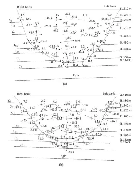
Fig.16.Stress distribution of upstream and downstream faces of arch dam under normal load combination(×0.1 MPa).(a)Upstream face.(b)Downstream face.
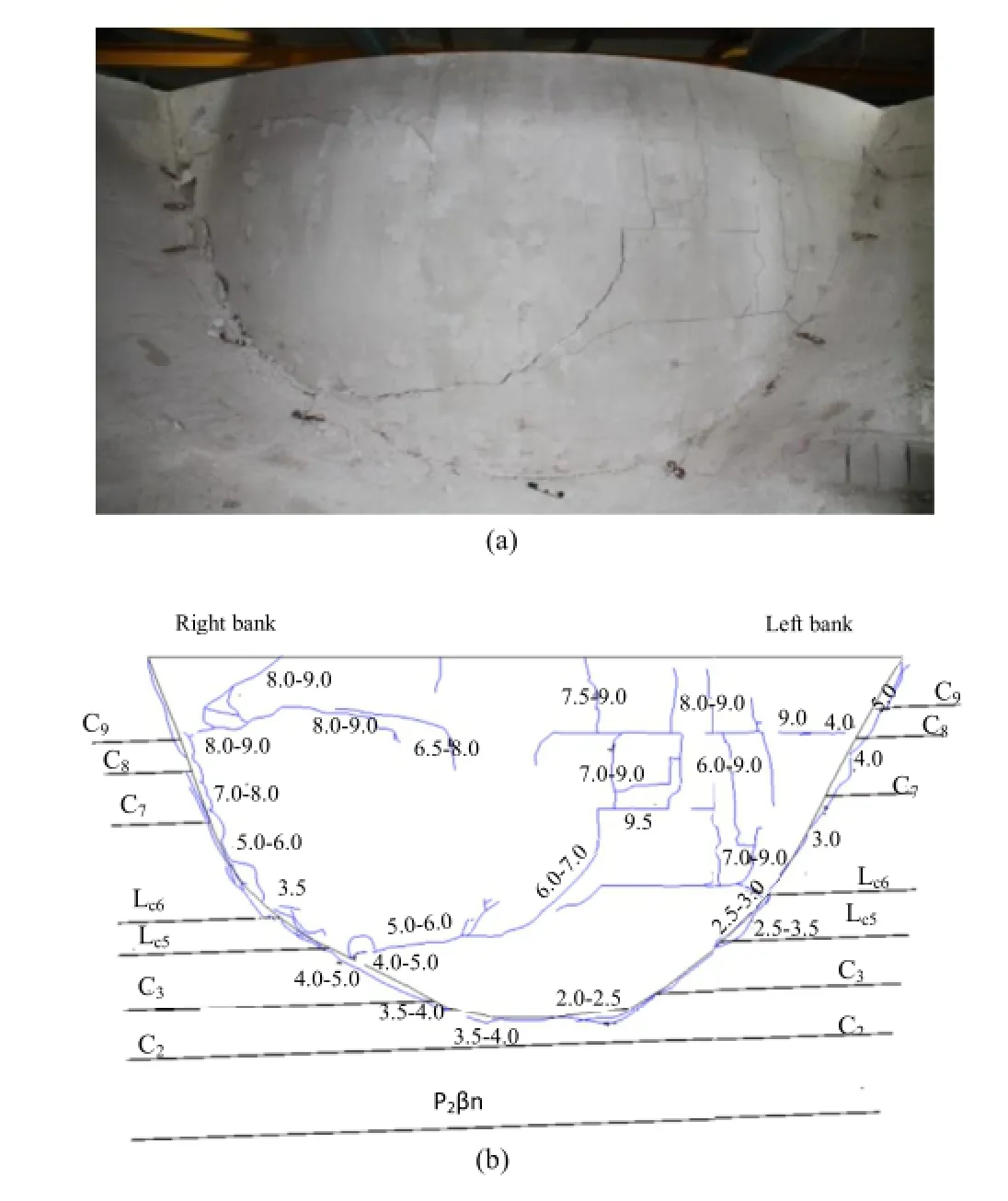
Fig.17.Failure process sketches of upstream and downstream faces of Xiluodu arch dam.(a)Upstream face.(b)Downstream face.The numbers are the overload coef f cients.
The tensile fracture loadofupstreamdamheelwasP1t=(2-2.5)P0, and the compressive fracture load of downstream dam toe wasP1c=(2.5-3)P0.The load when signi f cantly large deformation occurred wasP2=(5-6)P0,and the ultimate load capacity wasP3=(9-9.5)P0.The application of toe protection below the elevation of 359 m of dam foundation can signi f cantly improve the stress state of the dam,facilitating the upstream dam heel’s crack resistance and the downstreamdamtoe’s fracture resistance.Fig.17 shows the failure process of upstream and downstream faces of Xiluodu arch dam.
4.1.4.Rock foundation deformation and failure mechanism
When the load increased to 2P0,the upper and lower layers on the upstream side of left and right bank(Lc6)began to move.Dam foundation cracking appeared f rst on the upstream side of the top of right dam abutment,andP1was(3.5-4)P0.When the load increased to(5-6)P0,both the dam body and foundation suffered a relatively large deformation,and slippage and cracking took place in the left bank joints and inter-laminar and intraformational dislocation bands.When the load was(4-5)P0, compression and shear failure occurred in the left bank dam toe of the riverbed dam foundation.When it increased to(5-6)P0, compression and shear failure took place in the right bank dam toe.WhenPwas greater than8P0,left bank cracks opened and propagated downstream rapidly(at elevation of 530-390 m). Fig.18 illustrates the deformation and failure of arch dam and foundation.
4.2.3Dfnite element analyses of arch dam
4.2.1.Calculation method and working conditions
The strength of materials was calculated with Drucker-Prager (D-P)yield criterion as
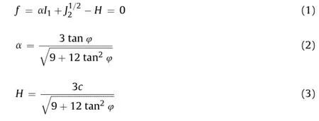
whereI1is the f rst invariant of stress,J2is the second invariant of stress,cis the cohesion,and φ is the friction angle.
The analysis is focused on the working conditions of fundamental scenario that could control the overall safety of the arch dam,i.e.the deadweight of dam body and rock mass,temperature effect,osmotic pressure,the water pressure and silt pressure under normal water level.The working conditions of overload effects are with the same load combination as the fundamental scenario,i.e. the overload is applied through continuous increase of the reservoir water level.
4.2.2.Grid model and materials parameters
Dimensions of the simulations were 1800 m×1203 m× 597 m,which were determined through the dam axis,i.e.the distances of 1 time dam height upstream,2 times the dam height on each of the left and right banks,and 2 times the dam height downstream,respectively.The depth was 1 time the dam height beneath the dam foundation.The grids totaled 25,088,and nodes of 28,647.The calculations considered the combination of various rocks,blocks C9,C8,C7,Lc6,Lc5,C3,C2,weak inter-layer P2βn(strip thickness of 0.3-1.5 m),foundation concrete replacement,and dam toe protection under targeted load combinations.Figs.19 and 20 show the simulated replacements of the toe and dam,and inter-laminar and intra-formational dislocation bands,respectively.Table 11 lists the parameters of various materials used.

Fig.18.Sketches of deformation and failure of arch dam and foundation during overload.(a)Final failure of rock mass on left bank.(b)Final failure of rock mass on right bank.(c)Sketch of deformation and failure of arch dam and foundation during overload(P1=(3.5-4)P0).The numbers colored in blue are overload coef f cients.

Fig.19.Sketch of relation among foundation concrete replacement,toe protection,and dam.

Fig.20.Sketch of the positions of inter-and intra-formational belts.
4.2.3.Analysis of arch dam stress and displacement
Under the normal load combination,the dam displacement was well distributed.The maximum radial displacement of the crown cantilever was 132.5 mm at the elevation of 610 m.The maximum radial displacement of left arch abutment was 27.7 mm,appearing on the downstream face at the elevation of 340 m.The maximum radial displacement of right arch abutment was 25.6 mm on the downstream face at the elevation of 450 m.
The maximum tangential displacement of crown cantilever was 11.5 mm,and the maximum tangential displacement of left arch abutment was 12.2 mm at the elevation of 560 m on the downstreamsurface.The maximumtangentialdisplacementofrightarch abutment was 12.2 mm at the elevation of 520 m on the downstream face.All deformation directions were towards the mountain.
Under normal load combination,the maximum main tensile stress of about 0.17 MPa was observed on the upstream dam face near the left arch abutment at elevation of 610 m.The compressive stress of downstream face increased gradually from the middle part of dam face to the arch abutment,and the high stress area was observed in vicinity of the arch abutment at low and medium elevations.The maximum principal compressive stress was about-16.59 MPa at the elevation of 380 m.The horizontal tensile stress appeared near the elevation of 470 m on the downstream dam face,and the maximum of about 1.13 MPa was found on the right side of the crown cantilever at elevation of 470 m.
4.2.4.Analysis of foundation stress displacement and point factor of safety
(1)Under the working condition of normal load combination,the maximum dam foundation displacement was 25.5 mm observed on the right arch abutment at the elevation 440 m. The difference of the displacements between top elevation and bottomelevation was relatively small,with maximum value not more than 12.5 mm.The displacements of upper and lower surfaces of the dislocation interfaces were relatively small.It can be noted that the rock mass of arch abutment was basically under compression state,and the dam and foundation were in an elastic working state.
(2)Under the working condition of normal load combination,the point factor of safety of arch abutment rock mass was greater than 1.2 on the bank sides,but larger than 1.5 in the deeper part.With consideration of geological faults and weak intercalation,the point factor of safety had the smallest value in the shallow layers on bank slopes at any elevation,but were basically greater than 1.5,meeting the requirement for anti-sliding points of arch abutment(see Table 12).The point factors of safety in the inter-laminar dislocation bands of arch abutment were greater than 1.2 on the bank sides,which were roughly1.5-2,and greater than 5-15 in deeper part.Their behaviors were all elastic under this working condition(see Table 13). Areas with smaller point factor of safety appeared on the upstream side of the dislocation interfaces,and on the shallow part of bank slope of left-bank C9,C7,Lc6on the downstream side.Some parts of the archabutment and right bank Lc6and Lc5were also reported with low point factor of safety.

Table 11Physico-mechanical parameters of various materials in the dam area.

Table 12Point factors of safety of arch abutment.
4.2.5.Analysis of dam stability under overload condition
When consolidating grouting for the riverbed dam foundation, revetment to slope and toe protection to the bottom structure,and optimization of the overall structural shapes of bottom structure were considered,the overall overload factors of safety of the arch dam can be calculated.The crack initiation overload coeffcient wasK1=2,the nonlinear deformation overload coeffcient wasK2=3.5-4,and the ultimate overload coeffcient wasK3=7-8.In the conditions of theK1andK2,the stress,deformation,thrust and other indicators of dam foundation were equal to those in the feasibility study scheme,and appeared to be larger than those in the optimization scheme.In the condition ofK3,the overload capacity was equal to that in the optimization scheme,and slightly lower than that in the feasibility study scheme.Under the condition of high water level,the displacement and stress matched with the criteria requirements.
5.Monitoring data analysis of foundation during the construction and initial impoundment periods
During the construction and initial impoundment periods of Xiluodu arc dam,the dam deformation recorded showed that the magnitude of the deformation is controllable when water level reached 560 m.The seepage fow increased slowly without abrupt changes with the upstream water level increasing.The osmotic pressure was relatively small in a global sense,which satisfed the design requirements.The compressive pressures of dam foundation and joints of foundation rock were varied regularly and reasonablyin a small range.The dam and foundationwerein a good working condition.

Table 13Point factors of safety of arch abutment in the inter-formational belt.
5.1.Analysis of arch dam foundation deformation
5.1.1.Dam foundation deformation
The settlement distribution curves of dam foundation showed that the deformation difference between adjacent dam sections was basically less than 1.8 mm.In the period of concrete cast-inplace of the dam,the foundation suffered a greater deformation with elapsed time under the action of deadweight.During impoundment,only the dam sections of foundation surface outlets suffered slight increase in deadweight when the joint grouting reached the elevation of 563.25 m.With the dam arch effect formed,the upward changes of foundation deformation associated with initial impoundment were minor.When water level reached 560 m,the maximum deformation of foundation was 31.21 mm observed in dam section 16,an increase of 4.67 mmwhen the initial water level reached 540 m in June 2013.Fig.21 presents the typical hydrograph of the relevant settlements at typical measuring points during impoundment.
5.1.2.Joint aperture of dam foundation
There were50 m embedded in the dam sections 3-29 and in the concrete replacement areas of Xiluodu arch dam foundation,for the purpose of measuring rock aperture between the base rock surface and the dam bottom surface.At present,the accumulative deformation recorded from the base rocks is-3.82 to 2.38 mm,which was considered to be compressive.In terms of deformation distribution,the compressive deformation of riverbed dam section was larger than that of the bank slope dam section,which was illustrated in a form of greater surplus thrust.The largest compressive deformation was recorded on the upstream side of dam section 17.
After impoundment,the imposed forces of upstream water increased.The dam foundation joints on the upstream side were open deforming,but those in the middle part and on the downstream side were under compression.Moreover,the compressive stress on the downstream side was greater than that in the middle part,which was most likely attributed to the increase in upstream water level.The riverbed dam sections(14-19)tended to be under tension at the upstream dam toe,with the maximum aperture of 0.31 mm recorded in dam section 14.The middle and downstream parts of the dam foundation were under compression,with the maximum downstream-side compressive deformation of 0.69 mm recorded in dam section 10(see Fig.22).
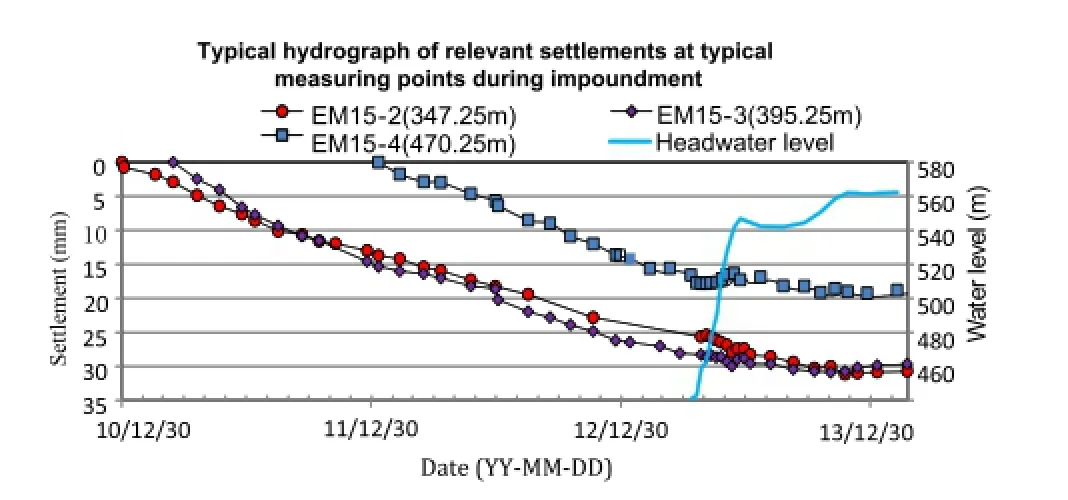
Fig.21.Typical hydrograph of relevant settlements at typical measuring points during impoundment.
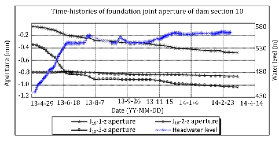
Fig.22.Time-histories of foundation joint aperture of dam section 10.
5.1.3.Osmotic pressure monitoring
During impoundment,the osmotic pressure behind the dam curtain decreased signi f cantly with the elevated water level.The measured water head of osmotic pressure behind the curtain was 0-51.81 m(dam section 15)with increment of water head of-1.41 to 24.63 m.The osmotic pressure coef f cienta1was 0.06-0.23,anda2was 0-0.08,meeting the requirements of design and criteria(a1is the uplift coef f cient,anda2is the residual uplift coef f cient).
5.2.Analysis of dam foundation stress state
The compressive stress of arch dam foundation was basically 0.19-7.34 MPa before impoundment,and varied from-0.06 to 2.45 MPa after impoundment.Due to the increasing forces applied by upstream water,the compressive stress of dam foundation on the upstream side tended to decrease after impoundment,by a maximum value of 1.14 MPa recorded at the elevation of 343.65 m of the dam section 12.The compressive stress of dam foundation on the downstream side tended to increase by a maximum value of 2.45 MPa recorded in dam section 10.In the same dam section,the decrease of upstream-side compressive stress was visibly equal to the increase of downstream-side compressive stress.The changing regulation of compressive stress of dam foundation was consistent with the changing rule of joint aperture of dam foundation.Figs.23 and 24 present the distribution of compressive stress of dam foundation and time-histories of compressive stress of typical dam sections,respectively.
5.3.Back analysis of monitoring results
For the purpose of understanding the overall performances of the dam,timely detection of various possible cracking risks during impoundment is necessary in terms of back analysis according to the monitoring data of the dam,which can facilitate impoundment arrangement in the next step.Therefore,the ACM was used to conduct feedback analysis using the monitoring data when the impoundment reached 540 m,in association with the subsequent impoundment plan.The key predication indicators for the arch crown beams in the condition of impoundment up to 560 m are:(1) radical displacement will be(7.76±3)mm to(21.56±5)mm;(2) vertical displacement will be(-3.03±2)mm to(29.06±3)mm (Liu et al.,2014).When the water level reached 560 m,the monitoring data of the crown cantilever at different elevations were all within the design values.Table 14 gives the vertical and radial displacements of dam section 15.
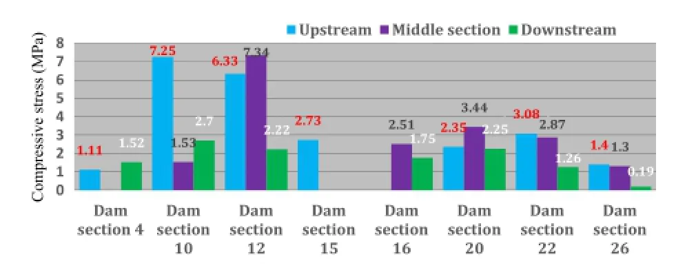
Fig.23.Distribution of compressive stress of arch dam foundation.
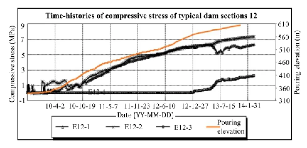
Fig.24.Time-histories of compressive stress of typical dam sections 12.
6.Conclusions
The optimization design of Xiluodu super-high arch dam is a complicated task,which is closely related to the site-speci f c geological conditions.Thus a process of dynamic optimization adjustment and timely safety evaluation is desirable.This optimization process requires the introduction of careful survey evaluation,key technologies,excavation optimization,body shape modi f cation and adequate structural design of arch dam,dam performance evaluation,adequate simulation analysis tools and/or geomechanical model test,feedback analysis of monitoring data, etc.
(1)At the feasibility study stage,the foundation surface of Xiluodu arch dam was considered to be mainly placed on the slightly weathered to fresh rocks II.
(2)At the optimization stage,the weakly weathered rocks III1and III2were used as foundation surface of the arch dam,which is reasonable and feasible through common analysis method,3D geomechanics model test,and 3D f nite element numerical analysis.Compared with the feasibility study scheme,the dam concrete volume was decreased by 1.1 million m3approximately,and the foundation excavation volume was decreased by around 1.61 million m3.The maximum excavation slope height on left and right banks was decreased by 40 m,with investments of nearly RMB 600 million saved.In addition, construction period can be shortened by 3 months.
(3)At the technical construction stage,according to the site
speci f c geological conditions revealed in riverbed dam foundation after excavation,the foundation excavation shape and foundation treatment requirements were adjusted in time,and the bottom foundation structure was optimized through the concepts of“overall extension of excavation+consolidatinggrouting+overall structure integrity+continuous cast-inplace concrete”.The foundation and dam body works well. Through 3D geomechanics model test and 3D f nite element analysis,the arch dam is considered to have a good dam stress, excellent overall stability and large overload capacity.This is also veri f ed by the monitoring data in the construction period and the initial impounding and operation periods.

Table 14Vertical and radial displacements of dam section 15.
(4)In view of the construction practices of Xiluodu arch dam,it is feasible to use rocks III1and III2as the foundation surface of super-high arch dam.But desirable reinforcement measures for the dam foundation must be taken.The structural optimization design is considered for the arch dam foundation by applying the forces on the arch dam to form a global dam foundation.At the same time,attentions should be paid to the geological conditions of dam section on riverbed.Thus advanced geological survey should be conducted prior to construction.
Con f ict of interests
The authors wish to con f rm that there are no known con f icts of interest associated with this publication and there has been no signi f cant f nancial support for this work that could have in f uenced its outcome.
Acknowledgments
The authors would like to thank the Chengdu Engineering Corporation Limited of Power Construction Corporation of China, Tsinghua University,and other Companies to provide the relevant results contributed to this paper!
American Society of Civil Engineers(ASCE).Foundations for dams.New York: American Society of Civil Engineers;1974.p.7-21.
Chengdu Hydroelectric Investigation&Design Institute of State Power Corporation (CHIDI).Final report on engineering design technology of Ertan hydropower station on Yaruo River.Chengdu,China:Chengdu Hydroelectric Investigation& Design Institute of State Power Corporation;2000(in Chinese).
Department of the Interior Bureau of Reclamation,USA(DIBR).Design criteria for concrete arch and gravity dams.United States:Department of the Interior Bureau of Reclamation;1977.
DL/T5346-2006.Design speci f cation for concrete arch dams.Beijing:China Electric Power Press;2007(in Chinese).
Fan Qixiang,Zhou Shaowu,Li Bingfeng.Key technologies of rock engineering for construction of Xiluodu super-high arch dam.Chinese Journal of Rock Mechanics and Engineering 2012;31(10):1998-2015(in Chinese).
HydroChina Chengdu Engineering Corporation(HCEC).Optimized design report of concrete arch dam of Xiluodu hydroelectric project on Jinsha River.Chengdu: HydroChina Chengdu Engineering Corporation;2005(in Chinese).
Li Zan,Chen Fei,Zheng Jianbo.Super-high arch dam hub analysis and key issue study.Beijing:China Electric Power Press;2004.p.1(in Chinese).
Lin Peng,Zhou Weiyuan,Yang Qiang,Yang Ruoqiong.The overall stability analysis and safety evaluation report of dam-foundation of Xiluodu arch dam.Beijing: Tsinghua University;2010(in Chinese).
Lin Peng,Wang Renkun,Kang Shengzu,Zhang Haichao,Zhou Weiyuan.Key problems of foundation failure,reinforcement and stability of superhigh arch dams. Chinese Journal of Rock Mechanics and Engineering 2011;30(10):1945-58(in Chinese).
Liu Dawen,Chen Xugao,Shao Naichen,Cai Dewen.Feedback analysis report of arch dam monitoring during initial impound of Xiluodu hydroelectric project on Jinsha River.Chengdu:HydroChina Chengdu Engineering Corporation;2014(in Chinese).
Liu Shihuang.Optimization of foundation surface of Laxiwa arch dam.Beijing: Hydropower Geology and Survey;1996.p.17-21(in Chinese).
Lu Youmei,Fan Qinxiang,Zhou Shouwu,Li Bingfeng.Key technologies for construction of Xiluodu high arch dam on Jinsha River.Journal of Hydraulic Engineering 2013;32(1):187-95(in Chinese).
SL282-2003.Design criteria for concrete arch dam.Beijing:China Water Power Press;2003(in Chinese).
SNiP 2.06.06-85.Design speci f cation of concrete and reinforced concrete dam. Moscow.1985.
Wang Qihong,Wang Miao,Ma Yile.Standard determination of usable rock mass of high arch dam.Journal of North China Institute of Water Conservancy and Hydroelectric Power 2010;31(4):123-6(in Chinese).
Wang Renkun.Analysis and evaluation on optimization of design for foundation interface of super high arch dam.Ph.D.Thesis.Beijing:Tsinghua University; 2007(in Chinese).
Wang Renkun,Yang Jianhong,Cui Changwu,Zhang Shaocheng,Chen Kui.Special research report of dam foundation treatment measures for Xiluodu hydroelectric project on Jinsha River(elevation of 510-610 m).Chengdu:HydroChina Chengdu Engineering Corporation;2007a(in Chinese).
Wang Renkun,Yang Jianhong,Cui Changwu,Zhang Shaocheng,Chen Kui.Special research report of dam foundation treatment measures for Xiluodu hydroelectric project on Jinsha River(elevation of 400-510 m).Chengdu:HydroChina Chengdu Engineering Corporation;2007b(in Chinese).
Wang Renkun,Yao Dewu,Chen Liping,Zhang Shaocheng.Report of rock mass geophysical prospecting testing results for dam foundation of Xiluodu hydroelectric project on Jinsha River.Chengdu:HydroChina Chengdu Engineering Corporation;2007c(in Chinese).
Wang Renkun,Lin Peng.Analysis and evaluation of optimizing design for foundation excavation of Xiluodu super-high arch dam.Chinese Journal of Rock Mechanics and Engineering 2008;27(10):2010-8(in Chinese).
Wang Renkun,Yang Jianhong,Cui Changwu,Zhang Shaocheng,Chen Kui.Special study on dam foundation treatment measures for Xiluodu hydroelectric project on Jinsha River(elevation below 400 m).Chengdu:HydroChina Chengdu Engineering Corporation;2008(in Chinese).
Wang Renkun,Yang Jianhong.Special design report of arch dam bottom structure of Xiluodu hydroelectric project on Jinsha River.Chengdu:HydroChina Chengdu Engineering Corporation;2009(in Chinese).
Yang Jianhong,Cui Changwu,Zhang Shaocheng,Chen Kui.Special research report of evaluation of geological conditions of dam foundation engineering for Xiluodu hydroelectric project on Jinsha River(elevation of 510-610 m).Chengdu: HydroChina Chengdu Engineering Corporation;2007a(in Chinese).
Yang Jianhong,Cui Changwu,Zhang Shaocheng,Chen Kui.Special research report of evaluation of geological conditions of dam foundation engineering for Xiluodu hydroelectric project on Jinsha River(elevation of 400-510 m).Chengdu: HydroChina Chengdu Engineering Corporation;2007b(in Chinese).
Zhou Weiyuan,Yang Ruoqiong,Lin Peng,Yang Qiang.3D geomechanics model test report of Xiluodu arch dam.1st ed.Beijing:Tsinghua University;2004(in Chinese).
Zhou Weiyuan,Yang Ruoqiong,Yang Qiang,Lin Peng.Research report of Xiluodu arch dam based on 3D FEM.Beijing:Tsinghua University;2006(in Chinese).
Zhou Weiyuan,Yang Ruoqiong,Yang Qiang,Lin Peng.3D geomechanics model test report of Xiluodu arch dam.2nd ed.Beijing:Tsinghua University;2010(in Chinese).
Zhu Bofang.Summary of topics of international seminar on arch dam.Hydropower 1988;8:49-52(in Chinese).

Dr.Qixiang Fangraduated from Gezhouba Institute of Hydro Electric Engineering with a B.S.in 1984,and obtained M.S.and Ph.D.from Tsinghua University in 1999 and 2010,respectively.He held several positions in the China Three Gorges(CTG)Project Preparatory Of f ce, including associate engineer in the Division of Technology in the Department of Construction Technology,project supervising engineer and leader of the supervision team of the Liyuan Project and later the Deputy Director of the Construction Division of the Liyuan Company.He served in CTG’s Construction Department as Deputy Director of the Division of General Management and later as the Director of the department,Director of the Division of Temporary Ship Lock Project and later the Director of the Division of Temporary Ship Lock and Ship Lift under the Left Bank Construction Department of the Three Gorges Project,the Deputy Director and later the Director of the Navigation Construction Department and Deputy Director of Management Department of Beijing National Aquatics Center(known as the Water Cube).He now is Executive Vice President of the CTG and is in charge of the construction of CTG’s Jinsha River hydropower projects.Dr.Fan is well experienced in management of large-scale complex hydropower projects,design,installation and testing of complex centralized control system,stability of high slopes,construction and installation of large-scale metal structures and structural concrete,etc.He has published over 80 papers.He has participated in the construction of several large-scale hydropower projects successively and made outstanding contribution to the construction and management of the TGP.
*Corresponding author.Tel.:+86 13208702033.
E-mail address:zhou_shaowu@ctgpc.com.cn(S.Zhou).
Peer review under responsibility of Institute of Rock and Soil Mechanics,Chinese Academy of Sciences.
1674-7755©2015 Institute of Rock and Soil Mechanics,Chinese Academy of Sciences.Production and hosting by Elsevier B.V.All rights reserved.
http://dx.doi.org/10.1016/j.jrmge.2015.03.001
 Journal of Rock Mechanics and Geotechnical Engineering2015年2期
- Journal of Rock Mechanics and Geotechnical Engineering的其它文章
- Laboratory study on the mechanical behaviors of an anisotropic shale rock
- Thermo-mechanical constitutive modeling of unsaturated clays based on the critical state concepts
- Monitoring result analyses of high slope of f ve-step ship lock in the Three Gorges Project
- UCIMS:Advances in geotechnical construction and performance monitoring
- Liquefaction evaluation of dam foundation soils considering overlying structure
- Improvement parameters in dynamic compaction adjacent to the slopes
