Inherent Relations among the Three Representations of Radar Target Angular Glint
Yin Hong-cheng Wang Chao Huang Pei-kang
(Science and Technology on Electromagnetic Scattering Laboratory,Beijing 100854,China)
Inherent Relations among the Three Representations of Radar Target Angular Glint
Yin Hong-cheng*Wang Chao Huang Pei-kang
(Science and Technology on Electromagnetic Scattering Laboratory,Beijing 100854,China)
Based on ElectroMagnetic (EM)theory and the monopulse radar angle measurement principle,the formulae of angular glint for complex target are proposed and generally applied to tackling practical problems. The inherent relations among the three representations of radar angular glint,i.e. the phase-front distortion concept,the energy-flow tilt concept,and the monopulse radar angular noise concept,are clearly demonstrated. The two existing concepts of angular glint are also revised. Thus,a firm theoretical foundation for understanding,modeling,simulating and suppressing the angular glint from complex radar targets is established.
Angular glint; Echo phase; Radar target; ElectroMagnetic (EM)scattering; Radar Cross Section (RCS); Monopulse radar
CLC index:TN957.52
1 Introduction
As an important ElectroMagnetic (EM)scattering signature of radar target other than Radar Cross Section (RCS),angular glint that often causes radar pointing to fall beyond the actual target extent[1]is the major error factors to severely affect the seeker tracking and homing guiding precision. Consequently,the reasonable modeling and simulation of the angle measurement error resulting from angular glint are of great importance for radar engineers to investigate the suppression techniques of angular glint in the design and evaluation of guidance systems.Attentions have been paid to the mechanism as well as calculation techniques of the angular glint for extended radar targets[2-14].
The phase-front distortion concept of angular glint was initially proposed by Howard[2],who interpreted angular glint as the tilt of wavefront normal resulting from a distortion of target echo signal phase by analyzing the phase front of the echo signal from an extended target consisting of two or multiple collinear,isotropic reflectors. Lindsay[3]extended Howard’s concept to represent glint effect by the phase gradient. Later on,based on an analysis of the echo signal from a target model consisting of a collinear,nonuniform array of electric dipoles by the derivation of the Poynting vector,Dunn and Howard[4]proposed the energyflow tilt concept to explain angular glint as a tilt of the echo signal propagating in space,and showed that two concepts are equivalent. Since then,both concepts from the analysis of two special target models have been widely accepted to explain angular glint phenomenon. Correspondingly,two techniques,i.e. the Phase Gradient Method (PGM)and the Poynting Vector Method (PVM),were adopted to calculate the linear deviations of angular glint for complex target[4-14].
Although no objection was raised against the correctness of the two concepts,there indeed exists an argument about the equivalence of them. Yin and Huang[15]noticed that the energy-flow propagating direction agrees with the wavefront normal under Geometrical Optics (GO)approximation,and firstly demonstrated that the equivalence between the two concepts exists only when GO approximation is made. Kajenski[16]showed that these two concepts yield identical results of angular glint by considering the polarization effect of the receiving antenna in Poynting vector analysis of a target model consisting of an electric dipole and a magnetic dipole. Further,Yin and Huang[17]analyzed the angular glint of a typical target consisting of two combined electric and magnetic dipoles with arbitrary orientation,and pointed out that both concepts yield identical results only when GO approximation is used and the receiving antenna is linearly polarized. As a complement and support of argumentation in Ref. [17],Wang et al.[18]provided a general discussion about the two concepts of radar target angular glint in view of ElectroMagnetic (EM)theory. From Refs. [2-4]and Refs. [15-17],it was concluded that both concepts are conditionally equivalent. This naturally motivates us to investigate a third problem: whether the angular glint calculated by either of the two concepts is consistent with the angular noise given by the angle error detector of a monopulse radar for an arbitrary target. The answer to the above question involves the joint formulation and analysis of EM scattering problem and monopulse radar angle measurement,and is certainly of great value for better understanding of the concepts as well as for reasonable modeling of angular glint.
Based on the rigorous EM theory and monopulse radar angle measurement principle,this paper aims at discovering the relationship among phase-front distortion concept,energy-flow tilt concept,and monopulse radar angle measurement principle so as to establish a firm theoretical foundation for simulation and suppression of angular glint. The remainder of the paper is organized as follows. In Section 2,the general formulae of angle measurement errors for sumdifference amplitude-comparison and phasecomparison monopulse radars are derived from EM theory. In Section 3,angular glint deviations obtained by phase-front distortion concept and energy-flow tilt concept are compared and analyzed with the angular errors given by monopulse radar angle measurements. We conclude the paper in Section 4.
2 Angular Glint in Terms of Monopulse Radar Angle Measurement
The past literatures clearly demonstrated the equivalence of two concepts of angular glint only when GO approximation is made and the receiving antenna is linearly polarized. In such case,which one is more accurate,or whether the angular glint calculated by either one coincides with angle noise given by angle error detector of monopulse radar,is the problem concerned. Therefore,it is required for us to obtain the general formulae of angular glint for complex target from EM theory and monopulse radar angle measurement principle as a benchmark of the following comparison and analysis.
Taking two representative cases for instance,the angular errors for sum-difference amplitudecomparison and phase-comparison monopulse radars[19]are formulated from EM theory in this section.

Fig. 1 ACS definition

Fig. 2 TCS definition and its relation to ACS


2.1 Angle measurement error formulation of sumdifference amplitude-comparison monopulse radar
Assuming that radar antenna axis initially points toward target center o,after radar begins to track target,the interference between echoes from the radiated sources of target makes it no longer aim at point o,and the corresponding angle deviation is namely angular glint of radar target. Let us consider the case in the elevation plane,where the directional functions of two antenna beams are identical to be Fθ(α),α is angle between scattered wave and principal axis of beam,and α0is angle of each principal axis deviated from antenna axis,as shown in Fig. 3.
For scattered wave with elevation angle ψ,the direction functions of sum beam and difference beam of the receiving antenna are respectively

From Eqs. (11a)and (11c)in Ref. [18],the received signals in sum and difference channels are respectively

where k=2π/ λ is the wave number,ŝ==r/r is the radial unit vector of scattering direction,and A(r',θ,ϕ)is defined as the receiving factor which describes polarization effect of the receiving antenna versus the radiated sources or the equivalent currents at r',see also Eq. (11c)in Ref. [18].

Fig. 3 Antenna beams of sum-difference amplitudecomparison monopulse radar
The elevation angle ψ and the azimuth angle ξ at r' in ACS can be respectively represented as
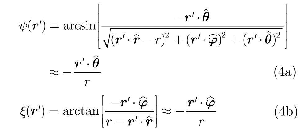
When radar tracks target,ψ(r')is usually very small (less than 2°),then the directional function of the receiving antenna in elevation plane is approximately

So the received signals in sum and difference channels in elevation plane are given by
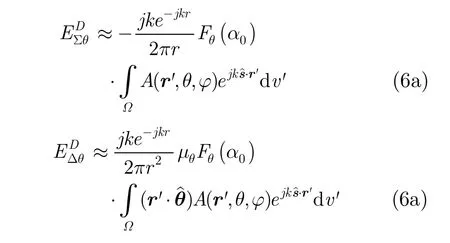
Then,the normalized voltage output by phase detector in elevation plane is

For sum-difference amplitude-comparison monopulse radar,angle measurement error ψ and the normalized voltage satisfy that

Using the first order Taylor series expansion,Eq. (8)is approximated as

From Eqs. (7)and (9),the angle measurement error is

So angular glint linear deviation in elevation plane is

Similarly,angular glint linear deviation in azimuth plane is

2.2 Angle measurement error formulation of sum-difference phase-comparison monopulse radar
In Fig. 4,the four receiving antennas of sum-difference phase-comparison monopulse radar are respectively located at four vertexes of a square with length 2a. The directional functions of four antenna beams are identical to be F(ψ,ξ),the principal axis of beam is chosen to be X direction.
The electric field received by No. 1 antenna at

where R1denotes the distance from the integral source point r' at target to point P1,R1≈r for computing the field amplitudes,and for computing the field phase,

Fig. 4 Geometry of four antennas of sum-difference phase-comparison monopulse radar

So the electric field received by No.1 antenna is approximated as

The electric fields received by Nos. 2,3,4 antennas can be also obtained by similar derivation,which are not given here as the length of paper is limited. In far-field zone of target,ψ(r')and ξ(r')are usually very small,and let F0≈F[ψ(r'),ξ(r')],then
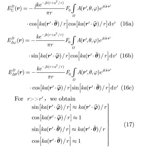
So the received signals in sum and difference channels are given by
Considering π/2 phase shift introduced in difference channel,the normalized voltage outputs by phase detectors in elevation plane and azimuth plane are respectively

For sum-difference phase-comparison monopulse radar,angle measurement error and the normalized voltage satisfy that

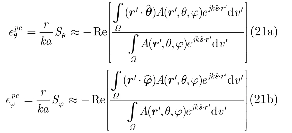
From Eqs. (19)and (20),we obtain angular glint linear deviations as
2.3 Comparison and analysis of two angle measurement error formulae
Comparison between Eqs. (11),(12)and (21a),(21b)shows that,angular glint linear deviations are the same for two kinds of angle measurement systems of monopulse radar,which means that angular glint only depends on target itself. The above formulae,which have never been presented in any published radar textbooks as far as we know,are easier to be implemented by the widely used high frequency techniques[20]or numerical methods[21,22]for solving EM scattering problems,and constitute the general expressions of angular glint linear deviations of complex target for arbitrary polarization of the receiving antenna.
From Eq. (21),the denominator in Re[⋅]operator is the far-field integral of the radiated source of target,i.e. the total scattered field,and the numerator in Re[⋅]operator is the far-field integral of this source weighted with its displace-ment from target center in elevation or azimuth plane,named as the source position vector projection weighted scattered field,all sensed by radar antenna,so angular glint linear deviation is shown to be the real part of the ratio of both them.
The N-point target as a collection of N isotropic point scatterers arbitrarily distributed in space given in radar textbook[23]is adopted to verify Eq. (21). In this case,the receiving factor and the position vectors of the ith scatterer are Aiand ri(i=0,1,…,N),respectively,the observation angles are (θ,ϕ),then the integrals of Eqs. (21a)and (21b)are simplified into the sum of all discrete sources,i.e.

For an isotropic point scatterer,Aican be given by

where Eiis the constant amplitude of scatterer,δiis the fixed initial phase of scatterer,and -k⋅ riis the phase delay caused by the path difference of incident wave. Let
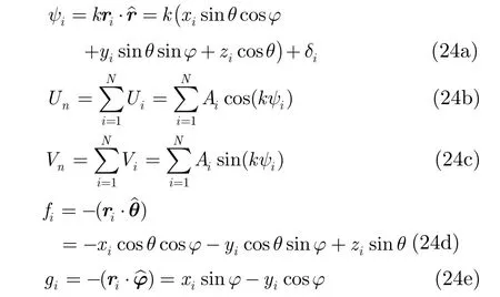
Substituting Eqs. (23)and (24)into Eq. (22),after simplification,Eqs. (22a)and (22b)become
Eqs. (25a)and (25b)are the well-known conventional expressions of angular glint linear deviations,which verify the correctness of Eq. (21)indirectly. For the N-point target consisting of N anisotropic point scatterers[11],Eq. (21)may be also similarly verified.
3 Inherent Relationships among the Three Representations
The expressions of angular glint linear deviation in Section 2,which are obtained from specific angle measurement radar systems based on rigorous EM theory,are general and can be used as benchmark to compare the related concepts and calculation methods.
A closed comparison between Eq. (24)in Ref. [18]and Eq. (21)shows that,the results obtained by PGM differ from those by monopulse radar angle measurement analysis,which evidently deviates from Howard’s authoritative explanation based on the phase-front distortion concept of angular glint[2]. However,due to the isotropic point scatterer assumption in Howard’s analysis,both the partial derivatives of A(r',θ,ϕ)with respect to θ and ϕ in Eq. (24)in Ref. [18]equal to zero,the results of PGM are just degenerated into ones of angle measurement analysis. Since scattering element has relation to observation angle in general case,Howard’s phase-front distortion concept should be revised to be that angular glint results from the phase-front distortion of echo signal caused by the variation rate of wave pathdifference of the radiated source of target with observation angle. Furthermore,the first term in Eq. (24a)or Eq. (24b)in Ref. [18]is identical to the result of angle measurement analysis,the additional second term is proportional to k-1and vanishes for k→∞. Therefore,the results of PGM are equivalent to those of angle measurement analysis under GO approximation (k→∞).
On the other hand,a comparison between Eq. (25)in Ref. [18]and Eq. (21)shows that,the results obtained by PVM differ from those by angle measurement analysis,too. However,if linearly polarized receiver (sin2θr=0 or sinδr=0)is used in Eq. (25)in Ref. [18],both are equivalent. Therefore,the energy-tilt concept should be restated as follows: angular glint of extended target may be represented by the energy-flow direction tilt of the echo signal propagating in space from the radial direction for a linearly polarized receiver.
For supporting the above discussion,as shown in Fig. 5,we consider an helicopter model with length 17.4 m,width 12.7 m,and height 6.1 m,and illuminated by a plane EM wave with an electric polarization vectorat 10 GHz propagating in the xoy plane,and calculate the appropriate azimuth and elevation data of angular glint linear deviations from Eqs. (24),(25)in Ref. [18]and Eq. (21)by using highfrequency method[24]. The predicted mono-static angular glint linear deviations of this model as a function of azimuth angle ϕ are respectively presented in Figs. 6 and 7 for linearly and elliptically polarized receivers withϕŝin30°andwhere the differences between the results by PGM or PVM and monopulse radar angle measurement (MRAM)respectively are also given in order to distinguish the discrepancy between the said two results more remarkably. For a linearly polarized receiver,PVM and MRAM lead to the same result,but there is a significant difference between them for an elliptically polarized receiver,and thus PVM can’t give correct results. For any large k,PGM gives the results deviated from MRAM,although the deviations,which depend on observation angle,frequency,polarization,etc.,are relatively small in most situations and can be neglected. Evidently,the inherent relationships among the three representations as mentioned are also indicated.

Fig. 5 Geometry of a helicopter model
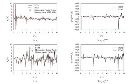
Fig. 6 Angular glint linear deviation of a helicopter model as a function of azimuth angle ϕ for a linearly polarized receiver
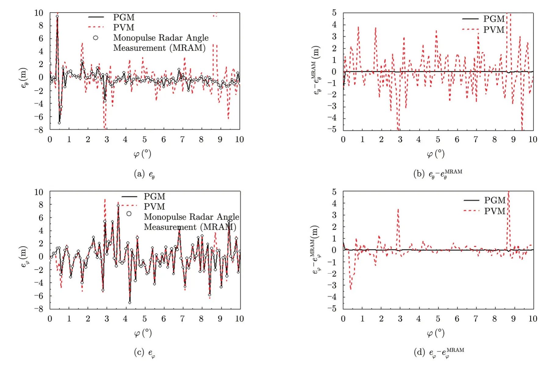
Fig. 7 Angular glint linear deviation of a helicopter model as a function of azimuth angle ϕ for an elliptically polarized receiver
To summarize,when PGM is applied to calculate angular glint of complex target,there is always a difference between PGM prediction and real value as long as λ≠0,because the rate of change of the amplitude and phase of the radiated source with observation angle is usually unable to be separated from echo signal of target. On the other hand,PVM can yield the same results as angle measurement analysis for the determined linear polarization reception. In this sense,it may be thought that PVM is accurate than PGM. In general,the formulae of angular errors derived from rigorous EM theory and monopulse radar angle measurement principle,i.e. Eqs. (11),(12)or Eqs. (21a),(21b),are suggested to be adopted in tackling practical problems.
4 Conclusions
The formulae of angular errors for sumdifference amplitude-comparison and phasecomparison monopulse radars obtained from rigorous EM theory are presented,and may be generally applied to tackling practical problems,from which angular glint linear deviation is shown to be the real part of the ratio of the source position vector projection weighted scattered field and the total scattered field,all received by the radar antenna. Further comparison and discussion about phase-front distortion concept,energy-flow tilt concept,and angle measurement error are given to demonstrate that angular glint of an extended target may be explained as the phasefront distortion of echo signal caused by the variation rate of wave path-difference of the radiated source of target as a function of observation angle,or as a distortion or tilt of the echo signal propagating in space when the receiving antenna is linearly polarized. PGM yields the same results of angular glint as angle measurement analysis under GO approximation,and so does PVM under linearly polarized receiving antenna. This work establishes a theoretical foundation for researchers to reasonably understand,model and simulate the angular glint of complex radar targets.
Acknowledgment The authors thank Professor Xiaojian Xu of Behang University for his kind assistance in polishing of this paper.
[1]Barton D K. Modern Radar System Analysis[M]. Dedham,MA: Artech House,1988.
[2]Howard D D. Radar target glint in tracking and guidance system based on echo signal phase distortion[C]. National Electronics Conference,USA,1959: 840-849.
[3]Lindsay J E. Angular glint and the moving,rotating,complex radar target[J]. IEEE Transactions on Aerospace and Electronic Systems,1968,4(2): 164-173.
[4]Dunn J H and Howard D D. Radar target amplitude,angle,and Doppler scintillation from analysis of the echo signal propagating in space[J]. IEEE Transactions on Microwave Theory and Techniques,1968,16(9): 715-728.
[5]Wright J W. On the statistical modeling of radar targets[D]. [Ph.D. dissertation],University of Illinois,1972.
[6]Mittra R,Lee S W,and Chuang C A. Analytic radar target modeling[R]. Antenna Laboratory Report,University of Illinois,1972.
[7]Borden B. A statistical glint/radar cross section model[J]. IEEE Transactions on Aerospace and Electronic Systems,1983,19(5): 781-785.
[8]Sandhu G S and Saylor A V. A real-time statistical radar target model glint/radar cross section model[J]. IEEE Transactions on Aerospace and Electronic Systems,1985,21(4): 490-507.
[9]Huang P K and Yin H C. Angular glint of the extended targets[J]. Journal of Systems Engineering and Electronics,1990,12(12): 1-17.黄培康,殷红成. 扩展目标的角闪烁[J]. 系统工程与电子技术,1990,12(2): 1-17.
[10]Sacchini J J. Simulation of a dynamic aircraft radar signature[R]. Air Force Institute of Technology,1996.
[11]Yin H C,Deng S H,Ruan Y Z,et al.. On the conditions for obtaining angular glint by backscattering echo relative phase[J]. Acta Electronica Sinica,1996,24(9): 36-40.殷红成,邓书辉,阮颖铮,等. 利用后向散射回波相对相位推求角闪烁的条件[J]. 电子学报,1996,24(9): 36-40.
[12]Xia Y Q,Yang H L,Xu P G,et al.. Predicting and calculating the glint of radar targets[J]. Journal of Radio Science,2003,18(1): 111-115.夏应清,杨河林,徐鹏根,等. 雷达目标角闪烁预估和计算[J].电波科学学报,2003,18(1): 111-115.
[13]Wang T,Wang X S,and Xiao S P. Suppressing the angular glint of polarimetric radar[J]. Journal of Radio Science,2004,19(6): 702-707.王涛,王雪松,肖顺平. 一种极化测量雷达的角闪烁抑制方法[J]. 电波科学学报,2004,9(6): 702-707.
[14]Sui M and Xu X J. Angular glint calculation via adaptive cross approximation algorithm[C]. IEEE International Symposium on Antennas and Propagation,Spokane,Washington,USA,2011: 2746-2749.
[15]Yin H C and Huang P K. Unification and comparison between two concepts of radar target angular glint[J]. IEEE Transactions on Aerospace and Electronic Systems,1995,31(2): 778-783.
[16]Kajenski P J. Comparison of two theories of angle glint: polarization consideration[J]. IEEE Transactions on Aerospace and Electronic Systems,2006,42(1): 206-210.
[17]Yin H C and Huang P K. Further comparison between two concepts of radar target angular glint[J]. IEEE Transactions on Aerospace and Electronic Systems,2008,44(1): 372-380.
[18]Wang C,Yin H C,and Huang P K. Comparison between two concepts of angular glint: general considerations[J]. Journal of Systems Engineering and Electronics,2008,19(4): 635-642.
[19]Leonov A I. Monopulse Radar[M]. Beijing: National Defense Industry Press,1974.列昂诺夫 А И. 单脉冲雷达(中译本)[M]. 北京: 国防工业出版社,1974.
[20]Weinmann F. Ray Tracing with PO/PTD for RCS modeling of large complex objects[J]. IEEE Transactions on Antennas and Propagation,2006,54(6): 1797-1806.
[21]Rao S M,Wilton D R,and Glisson A W. Electromagnetic scattering by surfaces of arbitrary shape[J]. IEEE Transactions on Antennas and Propagation,1982,30(5): 409-418.
[22]Song J M and Chew W C. Multilevel fast—multipole algorithm for solving combined field integral equations of electromagnetic scattering[J]. Microwave and Optical Technology Letter,1995,10(10): 14-19.
[23]Huang P K,et al.. Radar Target Signature Signal[M]. Beijing: Aerospace Press,1993.黄培康,等. 雷达目标特征信号[M]. 北京: 宇航出版社,1993.
[24]Wang C. High frequency EM scattering modeling and its application[D]. [Ph.D. dissertation],Communication University of China,2009.王超. 高频电磁散射建模方法及其工程应用[D]. [博士论文],中国传媒大学,2009.

Yin Hong-cheng (1967-)was born in Yujiang,Jiangxi province. He received the Ph.D. degree from Southeast University in 1993. He is now a research scientist of Science and Technology on EM Scattering Laboratory. His research interests include EM scattering modeling and radar target signatures.
E-mail: yinhc207@126.com

Wang Chao (1979-)was born in Xi’an,Shanxi province. He received the Ph.D. degree from Communication University of China in 2009. He is now a senior engineer of Science and Technology on EM Scattering Laboratory. His research interests include EM scattering modeling and radar target signatures.
E-mail: wangc207@126.com

Huang Pei-kang (1935-)was born in Shanghai. He received the B.S. degree from Nanjing Institute of Technology in 1956. He is now an academician of the Chinese Academy of Engineering and director of academic committee of Science and Technology on EM Scattering Laboratory. His research interests include radar target signatures and automatic target recognition.
E-mail: peikanghuang@vip.sina.com
雷达目标角闪烁三种表示的内在联系
殷红成 王 超 黄培康
(电磁散射重点实验室 北京 100854)
该文利用严格的电磁散射理论,推导了基于振幅和差式和相位和差式单脉冲雷达测角原理的复杂目标角闪烁的一般表达式,对雷达目标角闪烁的两种物理概念提出了新的解释和认识,揭示出波前畸变概念、能流倾斜概念和雷达角噪声产生原理三者之间的内在关系。该文工作为角闪烁的正确理解、建模仿真和抑制提供了理论依据。
角闪烁;回波相位;雷达目标;电磁散射;雷达散射截面(RCS);单脉冲雷达
TN957.52
A
2095-283X(2014)02-0119-10
10.3724/SP.J.1300.2014.14025
Manuscript received January 29,2014; revised January 29,2014. Published online March 6,2014.
Supported by the National Government Foundation of China.
*Corresponding author: Yin Hong-cheng.
E-mail: yinhc207@126.com.

