
Mathematical Model of Natural Gas Desulfurization Based on Membrane Absorption
2014-07-31 23:15:49WangShuliMaJunWangGanyuZhouHeng
中国炼油与石油化工 2014年4期
Wang Shuli; Ma Jun; Wang Ganyu; Zhou Heng
(1. Jiangsu Key Laboratory of Oil-gas Storage and Transportation Technology, Changzhou University, Changzhou 213016; 2. School of Petroleum Engineering, Changzhou University, Changzhou 213016; 3. Changzhou Institute of Engineering Technology, Changzhou 213164)
Mathematical Model of Natural Gas Desulfurization Based on Membrane Absorption
Wang Shuli1,2; Ma Jun1,2; Wang Ganyu3; Zhou Heng2
(1. Jiangsu Key Laboratory of Oil-gas Storage and Transportation Technology, Changzhou University, Changzhou 213016; 2. School of Petroleum Engineering, Changzhou University, Changzhou 213016; 3. Changzhou Institute of Engineering Technology, Changzhou 213164)
Models of mass transfer kinetics combined with mass transfer differential equation and mass transfer resistance equation were established on the basis of double-film theory. Mass transfer process of H2S absorption by means of polypropylene hydrophobic microporous hollow fiber membrane contactor was simulated using MDEA (N-methyldiethanolamine) as the absorption liquid and corresponding experiments of natural gas desulfurization were performed. The simulation results indicated that the removal rate of hydrogen sulfide showed positive dependence on the absorption liquid concentration and gas pressure. However, the desulfurization rate showed negative dependence on gas flow. The simulated values were in good agreement with the experimental results. The in-tube concentration of hydrogen sulfide at the same point increased with increase in the gas velocity. Axial concentration of hydrogen sulfide decreased rapidly at the beginning, and the decrease saw a slowdown during the latter half period. Hydrogen sulfide concentration dropped quickly in the radial direction, and the reduction in the radial direction was weakened with the increase of axial length due to the gradual reduction of hydrogen sulfide concentration along the tube. The desulfurization rate under given operating conditions can be predicted by this model, and the theoretical basis for membrane module design can also be provided.
membrane based absorption; H2S; simulation; mass transfer
1 Introduction
Natural gas is considered to play an extremely important role in the industrial and civil service sectors in the coming decades. And it is also worth noting that natural gas is the cleanest and safest energy source among all sorts of energy. However, hydrogen sulfide contained in untreated natural gas is a kind of extremely corrosive, toxic and irritant gas, functioning as a catalyst poison in the humid and heat environment under aerobic condition, which would cause corrosion of equipment and pipelines[1]and even could pose a serious threat to personal safety. Currently, wet desulfurization process using amine solution is a widely used desulfurization technology. MDEA (N-methyldiethanolamine) has gained its popularity because of its relatively high working concentration, small circulating volume, moderately good degradation resistance and other favorable features[2]. Nevertheless, several parts of desulfurization devices would be seriously corroded during the process of wet desulfurization inside the tower[3].
Additionally, some obstacles have been encountered with the development of desulfurization technology as a consequence of liquid flooding, weeping, entrainment and foaming as well as other shortcomings[4].
Desulfurization based on membrane absorption is a new technology, which combines the advantages of membrane technology in the absorption process. Its contact area can amount to 3 000—5 000 m2/m3thanks to the high packing density of hollow fiber membrane contactor, which is 30—50 times greater than the conventional absorber. Whereas, any combination of devices connected either in series or in parallel can be possible to form the membrane contactor operated as a unit. And advantages of manufacturing process scale-up, easy industrialization, compact device with small plot area, less investment, simple manipulation as well as low cost can be realized.
The polypropylene hollow fiber membrane module and methyldiethanolamine solution were employed as the absorber and absorption liquid, respectively, in reference[5-6]and their effects on mass transfer coefficient and removal rate of H2S were investigated by changing operating conditions (such as temperature, gas-liquid phase flow, pressure, absorption solution concentration, etc). The results showed that the desulfurization rate could reach 95% by optimal combination of operating conditions. Mathematical models used generally by researchers at home and abroad are mass transfer differential equations. Wang, et al.[7]simulated the effects on CO2absorption rate by changing various parameters of the mass transfer differential equation. Chen, et al.[8]simulated the concentration distribution of different kinds of reactions and their products in membrane module with the mass transfer differential equation established for acid gas absorption process as well, but the in-tube concentration distribution of hydrogen sulfide was not involved. Faiz, et al.[9]simulated the effects of various operating parameters on sour gas removal rate with the mass transfer differential equation, and the distribution of acid gas was studied as well. Hua, et al[10]. studied the impact of various operating conditions on the CO2removal rate coupled with the establishment of two-dimensional mathematical model. An improvement of model fitting effect can be achieved by introducing the wetting coefficient. The establishment of mass transfer kinetics models combining mass transfer differential equation and mass transfer resistance equation on the basis of double-film theory was illustrated in this paper. Simulation of the operating parameters’ effects on desulfurization rate was referred to and the in-tube distribution of H2S concentration was also involved.
2 Desulfurization Theory
Water ionization, MDEA protonation, primary and secondary ionization of H2S existing in H2S-MDEA-H2O system and detailed processes are shown as follows:
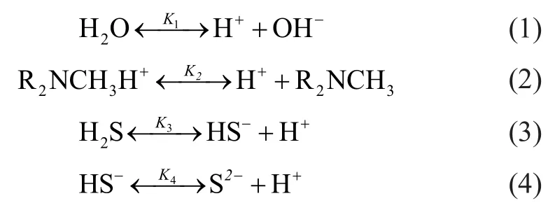
The mechanism for removal of hydrogen sulfide in natural gas with MDEA solution can be summarized as follows. The primary and secondary ionization process took place successively, when hydrogen sulfide was mixed with the MDEA solution. And the protonation between MDEA and the produced hydrogen ions in the solution occurred. Hydrogen sulfide ionization continued endlessly due to the reduction of hydrogen ion concentration, and therefore hydrogen sulfide was continuously dissolved in MDEA solution. The concentration of each component in the H2S-MDEA-H2O system was calculated by making reference to the solubility model of Li[11].
3 Mass Transfer Process and Resistance Equation
Polypropylene hollow fiber membrane module and methyldiethanolamine solution were respectively employed as the absorber and the absorption liquid for removal of hydrogen sulfide from natural gas. Natural gas and absorption liquid was introduced into the tube side and shell side, respectively. And the way of reverse flow was also applied during the absorption process. Boundary layer was formed near both sides of the membrane surface in the course of flow of gas and liquid at each side of the membrane. The membrane pores were filled with gas when membrane was not wetted, and a gas-liquid interface was formed near the membrane pores at the liquid side. Hydrogen sulfide reacted on methyldiethanolamine in the absorption liquid and a few hydrogen sulfide molecules were dissolved in the solution. The hydrogen sulfide concentration decreased continuously when H2S molecules diffused from gas phase to the gas boundarylayer, and then diffused through membrane pores and reached the gas-liquid contact surface under the effect of concentration difference. The methyldiethanolamine molecules continuously diffused from liquid phase to the liquid boundary-layer, and then to the gas-liquid contact surface. Then, the reaction products diffused to the liquid phase under the effects of concentration difference.
Hydrogen sulfide can be easily dissolved above the interface due to small resistance. Therefore, the requirement for physical equilibrium can be satisfied by solute concentration of two-phase at the gas-liquid interface, and the mass transfer resistance hereupon can be ignored. The related mass transfer resistance existing during the absorption process included: the mass transfer resistance in thegas phase, the mass transfer resistance in the membrane, and the mass transfer resistance in the liquid phase. According to the resistance-in-series model, the mass transfer flux of hydrogen sulfide in the membrane modules can be expressed as follows:

The mass transfer process of hydrogen sulfide absorbed by the absorption liquid through the hollow fiber membrane tube is described in Figure 1.
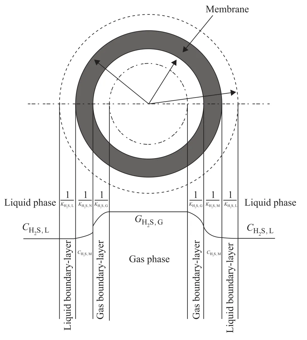
Figure 1 Mass-transfer regions, dominant resistance and flow configuration in a membrane gas absorption process
It can be seen from Figure 1 thatare gas phase, gas-membrane contact surface, gas side of gas-liquid contact surface, liquid side of gas-liquid contact surface, and hydrogen sulfide concentration of liquid phase, respectively;mis the distribution coefficient of hydrogen sulfide in gas-liquid phase. The distribution coefficient of H2S in pure water is 2.53 at 298.15 K.are mass transfer resistance of gas boundary-layer, membrane and liguid boundary-layer, respectively. Therefore, the total mass transfer resistance isduring the chemical absorption, in which E is the enhancement factor, andis the mass transfer coefficient of the physical absorption.
3.1 Process of mass transfer in the tube side
Transmission of gaseous component A in the radial direction (i.e. perpendicular to the flow direction) was a molecular diffusion when gas flow in the tube side of hollow fiber membrane was in a state of laminar flow. The mass transfer coef ficientof gas phase can be calculated by the following equation:

whered1is the tube diameter (m) of fiber membrane;ugis the gas velocity (m/s) in tube side; L is the tube length (m) of fiber membrane;DA,gis the diffusion coefficient of gas phase, which can be calculated by an empirical relationship of gas molecule movement.

3.2 Mass transfer in membrane
According to the kinetic theory of gas molecule[12], the form of gaseous molecules passing through porous solids includes the Knudsen diffusion (not in conformity with diffusion of Fick’s law), the molecular diffusion, the Poiseuille flow and the surface diffusion. The surface diffusion was not obvious and could be ignored when the pore size was over 0.02 μm; the Poiseuille flow disappearedwithout pressure gradient. The Knudsen number (Kn), as the ratio of mean free pathversus membrane pore size, was used to determine the dominant form of mass transfer under given experimental conditions[13]. Collisions between molecules and inner wall of membrane pores occupied a predominant share in mass transfer processes, and the Knudsen diffusion mainly took place whenKnwas over 20. Collisions among molecules as well as between molecules and the inner wall of membrane pores was a combination of membrane and molecular diffusion, which constituted a predominant share in mass transfer processes whenKnwas in the range of 0.02 and 20. Mass transfer processes were based on collisions of molecules, and molecular diffusion mainly occurred whenKnwas under 0.02.


The gas mixture of methane and hydrogen sul fide was used as the simulation gas in this paper, which was introduced into the membrane modules with a pore size of 0.1 μm under a pressure of 0.02—0.1 MPa. Herewas equal to 0.375 8 nm, andKnwas between 1.333 5 and 6.667 3 at 293 K. Therefore, the gas diffusion including the Knudsen diffusion and molecule diffusion occurred in membrane pores. The coef ficient of Knudsen diffusion is expressed asand the total coefficient of effective diffusion can be shown as:
The mass transfer resistance in membrane depends not only on the wetting condition of membrane, but also on the geometric structure of membrane thickness, curvature and porosity of the membrane. The coefficient of mass transfer can be determined when the membrane was not in a wetted state by the following equation:
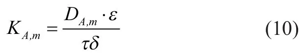
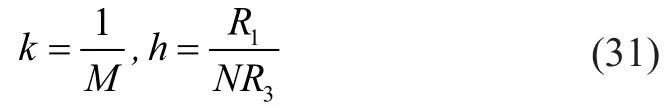
whereεis the porosity (non dimensional);δis the membrane thickness (m);τis the curvature factor which is expressed asThe porosity and thickness of fiber membrane according to manufacturer’s specification are 0.474 and 100×10-6m, respectively. The estimated value ofDA,mandKA,mis 3.37×10⁻¹⁰m2/s and 3.25×10⁻⁷m/s, respectively.
3.3 Mass transfer in shell side
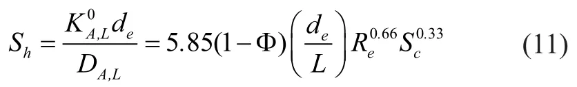
When liquid in the shell side is in a state of laminar flow, the liquid phase mass transfer coefficient ofin physical absorption process can be calculated as follows:
The diffusion coef ficient of hydrogen sul fide in pure water can be calculated by the following equation[14]:
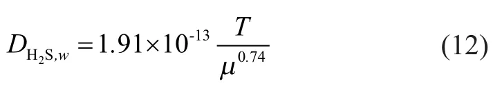
The estimation for diffusion coefficient of hydrogen sulfide in the feed liquid can be expressed by the following equation:

In comparison with physical absorption, the distribution of solute concentration was changed by chemical absorption which caused acceleration of mass transfer rate in liquid phase and enhancement of mass transfer rate during the whole absorption process due to the reactive consumption of soluble components in liquid phase. The mass transfer coefficient of liquid phase during theabsorption process accompanied by chemical reaction can be defined as follows:

The reaction between alcohol amines and hydrogen sulfide can be considered as a fast reaction, in which the reactive enhancement factorEequals to the Hatt number

The expression of total mass transfer resistance for hydrogen sul fide diffusing from tube side to the shell side can be illustrated as follows:

The gas-phase mass transfer resistance is nearly equal to the mass transfer resistance of membrane, which accounts for the largest proportion of total mass transfer resistance. The mass transfer resistance of liquid phase is virtually zero, which is negligible. The gas flow has an influence on the gas-phase mass transfer resistance, without affecting, however, the membrane and liquid phase. The gasphase mass transfer resistance and total mass transfer resistance showed a negative dependence on the gas flow.
4 The Mass Transfer Differential Equation
It was assumed that the fluid in the tube side and shell side was both axial-symmetric flow, and its flow model is depicted in Figure 2, in whichR1is the inner radius of membrane,R2is the outer radius of membrane, andR3is the position with the maximum velocity of shell-side liquid.
Hypotheses were proposed on the basis of mass transfer characteristics in membrane absorption process when membrane modules were under a steady-state operation: (1) Since the in-tube gas flow was in a state of fully developed laminar flow, the velocity distribution exhibited a parabola simultaneously, and the shell-side absorption liquid flowing in the reverse direction was in a state of laminar flow as well.
(2) The entire model was divided into three independent phases of gas, membrane and liquid, respectively. Thereby, an approximate analysis of axial symmetry could be obtained due to the absence of angular gradient.
(3) Flow pattern had been fully developed and material concentration was evenly distributed at the entrance of both tube side and shell side.
(4) The dissolved quantity of methane in absorption liquid could be ignored.
(5) Gas is considered as ideal gas, and pressure drop of gas in the axial direction can be ignored.
(6) The membrane was under a non-wetting condition.
(7) The gas solubility in liquid phase obeyed the Henry’s law.
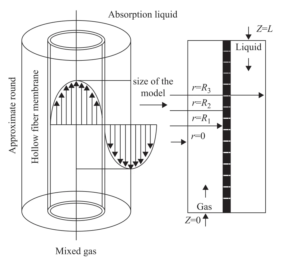
Figure 2 Flow model in the hollow fiber membrane
4.1 Mass transfer in tube side
The in-tube transfer forms of hydrogen sulfide included diffusion and convection, and mass conservation of hydrogen sulfide for in-tube transferring under steady-state could be explained by the following equation.


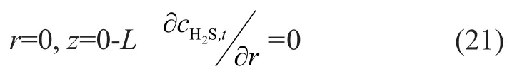
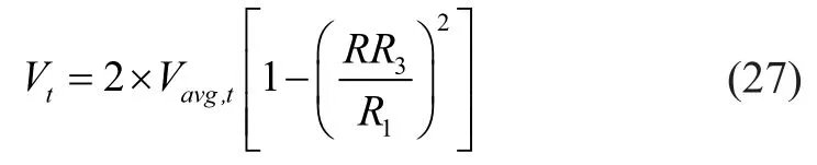
whereVtis the in-tube velocity component (m/s) in the axial direction; andVavg,tis the average in-tube velocity(m/s). According to the third hypothesis, the initial boundary condition can be determined as follows:

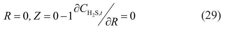
wherecH2S,t,inis the hydrogen sul fide concentration at the gas inlet. A conclusion on tubular axis can be drawn with consideration of the symmetric diffusion:
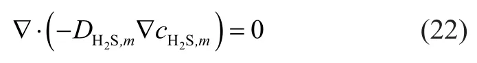
4.2 Mass transfer in membrane phase
The material transfer in membrane phase was in the form of diffusion when the mass transfer process took place under a steady state. Mass conservation of hydrogen sulfide can be described as follows:
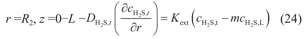
According to the sixth hypothesis, the mass conservation equation of membrane inner wall can be obtained as follows:
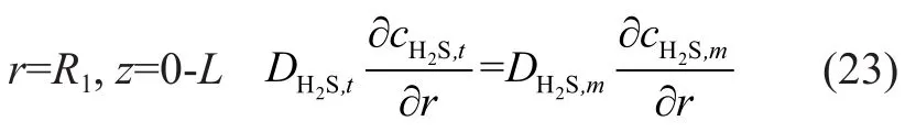
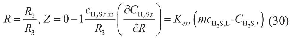
According to equations (5) and (24), the mass transfer flux of absorbed component in the outer wall of membrane was equal to the gaseous mass transfer flux during the process of mixed gas absorption. A conclusion corresponding to H2S in the mixed gas can be drawn as follows:
5 The Model Solution
5.1 Nondimensionalization
Nondimensionalization should be applied on mass transfer differential equation initially in order to solve the equation easily by means of the MATLAB software.
The velocity equation (19) was transformed as follows:
The initial boundary condition (20) was changed to:
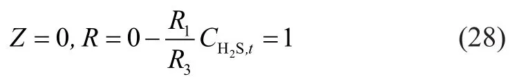
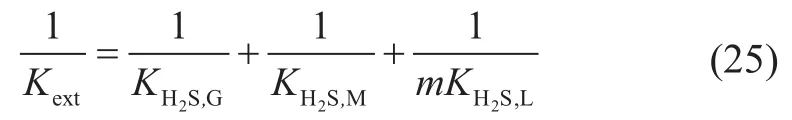
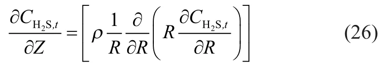
The equation (21) was converted into:
The equation (24) was changed to:
5.2 Discretization
The differential equations were discretized by different equations, andMandNgrids were taken respectively in the axial (Zdirection) and radial (Rdirection) directions of hollow fiber membrane tube, then:
Thus the original concentration functionC(Z,R) with variablesZandRwas transformed into discrete functionC(m,n) of grid variables in the axial (Zdirection) and radial (Rdirection) directions.

Then the following formulas were derived from the discretization of equations from (26) to (30) by equations (32), (33) and (34).
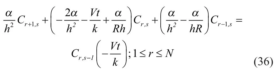
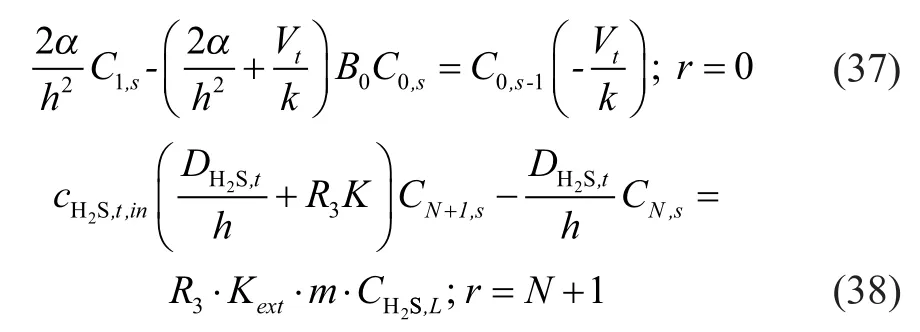
Equations with closed boundary were formed from discrete equations (36), (37) and (38); and the coefficient forms of equations were three diagonal matrices. Therefore, the chase method (Thomas method) was adopted for solving the equation. Finally, programming calculation was performed with the MATLAB software.
6 Experimental
6.1 Absorption process
The experimental setup is exhibited in Figure 3. The natural gas in steel cylinder was introduced into a heat exchanger (4) to be preheated to 303 K after passing through a pressure reducing valve (3), and was then routed through the fiber tube side of membrane contactor, with the gas flow rate being measured by a gas flowmeter (5). The requirement for keeping the gas phase pressure to be lower than the liquid phase pressure by 0.02 MPa should be satisfied because of application of the hydrophobic membrane. Natural gas in membrane pores came into contact with the absorption liquid, when H2S gas was absorbed by the absorption liquid flowing through shell side of contactor. The treated natural gas was collected after measurement by the gas flowmeter (5). The absorption liquid in tank (10) was pumped into the shell side of contactor through an alkali pump (8), and then was routed through the tank (9) after absorbing H2S gas. Sampling and analysis were launched after a stabilization period of 30 min as indicated in each instrument, and the sulfur content measurement was performed by a THA-200 micro-coulometer.
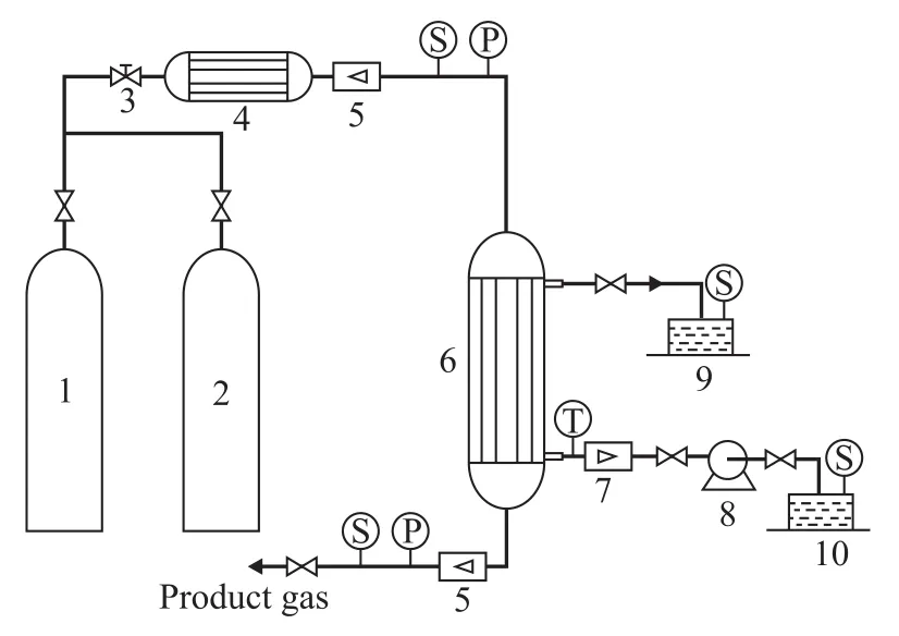
Figure 3 Schematic diagram of experimental apparatus
The structure and parameters of membrane as well as membrane modules used in the experiments are presented in Table 1.

Table 1 Module parameters adopted in experiment
6.2 Experimental data processing
Desulfurization rate (R) is calculated by the following equation:
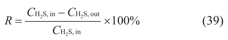
whereCH2S,inis the hydrogen sulfide concentration (mg/m3) at the inlet of membrane;CH2S,outis the hydrogen sulfide concentration (mg/m3) at the outlet of membrane;Ris the desulfurization rate, %.
7 Results and Discussion
7.1 Effect of gas flow on desulfurization rate
It can be seen from Figure 4 that the desulfurization rate decreased with an increasing inlet gas flowrate due to the overflow of unreacted H2S from membrane modules, which could be attributed to the reduction of retention time resulted from the increase of gas flow rate. On the other hand, the weakening of gas phase boundary-layer and the decrease of gas resistance as well as the enhance-ment of H2S diffusion flux in membrane pores were attributed to the increase of gas flow rate, namely the gas flux. Then the desulfurization rate increased with a decreasing concentration of hydrogen sulfide at the outlet[15-16].
7.2 Effect of absorption liquid concentration on desulfurization rate
The gas pressure was set at 0.006 MPa. It can be noted from Figure 5 that the desulfurization rate showed a positive dependence on the absorption liquid concentration. Absorption of H2S occurred in the gas-liquid interface, and the total coefficient of mass transfer showed a positive dependence on the absorption liquid concentration, which can be attributed to the increase of enhancement factor in chemical reaction process and liquid-phase mass transfer coefficient resulted from an increasing absorption liquid concentration. The desulfurization rate approached its limit when the absorption liquid concentration reached a certain value, thus there was no need to further increase the concentration[15].
7.3 Effect of gas pressure on mass transfer coefficient and desulfurization rate
The requirement for keeping the gas phase pressure lower than the liquid pressure by 0.02 MPa should be satisfied in order to prevent the absorption liquid from entering the membrane pores. It can be seen from Figure 6 that the desulfurization rate showed a positive dependence on the gas phase pressure due to the increase of total mass transfer coefficient and partial pressure of hydrogen sulfide in gas phase resulted from the increase in gas pressure. According to Henry’s law, the solubility in the absorption liquid also increased which was beneficial to H2S absorption.
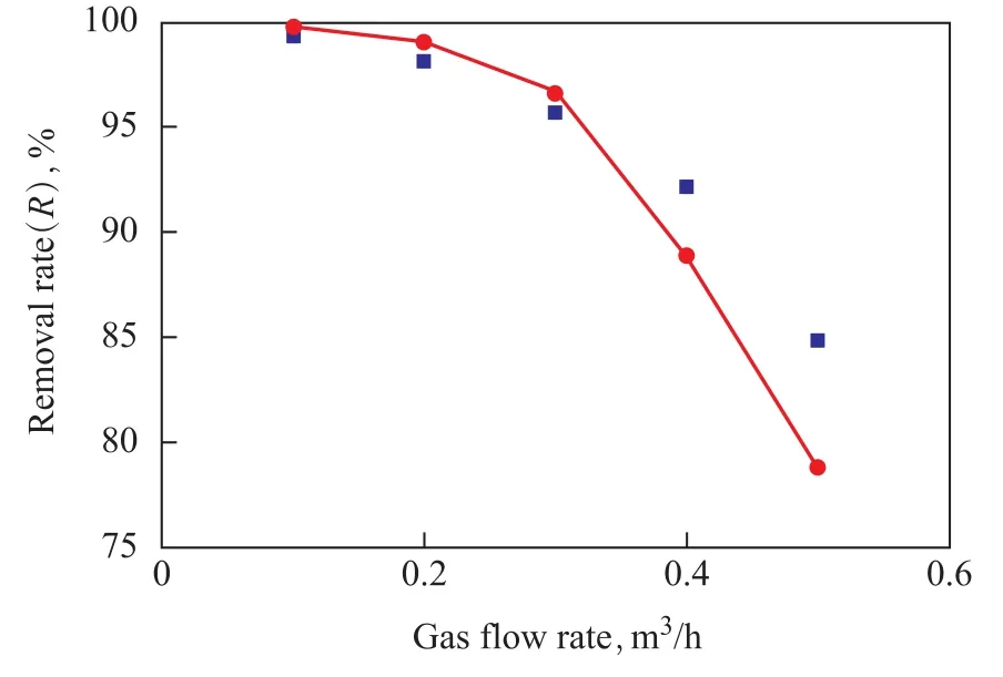
Figure 4 Effect of gas flow rate on removal efficiency

Figure 5 Effect of MDEA concentration on removal efficiency
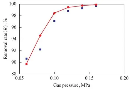
Figure 6 Effect of gas pressure on removal efficiency
8 Analysis and Discussion on Mass Transfer Characteristics of Fiber Tube
8.1 Dimensionless concentration development in the axial direction
The axial length of hollow fiber tube was divided into 20 segments, the dimensionless concentration distribution of hydrogen sulfide at segment points in the axial direction is exhibited in Figure 7, indicating that the hydrogen sulfide concentration at the same segment points increased with an increasing gas flow rate. The axial concentration of hydrogen sulfide dropped rapidly at the beginning, and the decrease saw a slowdown during the latter half period. A lower gas flow rate was preferred for hydrogen sulfide absorption. Reasons can be attributed to the high concentration of hydrogen sulfide at the beginning and rapid reduction of in-tube concentration resulted from hydrogen sulfide which could diffuse along the radial direction under the concentration effect. Mass transfer of hydrogensulfide was weakened due to the decrease of concentration difference resulted from a decreasing hydrogen sulfide concentration. Whereas, the in-tube retention time of hydrogen sulfide was extended by low gas flow rate, which was conducive to hydrogen sulfide absorption.
8.2 Dimensionless concentration development in the radial direction
The radial and axial length were both divided into 20 segments from the center of hollow fiber tubes, and the dimensionless concentration distribution of hydrogen sulfide at segment points in the axial direction is depicted in Figure 8. It can also be seen from Figure 8 that hydrogen sulfide concentration in the radial direction dropped rapidly, the amplitude of decrease was gradually weakened in the radial direction with the increase of axial length due to the gradual reduction of hydrogen sulfide concentration along the tube, which could be attributed to the reduction of in-tube diffusion of hydrogen sulfide in the radial direction with its concentration decreasing at a certain gas velocity, along with the reduction of diffusion rate as well.
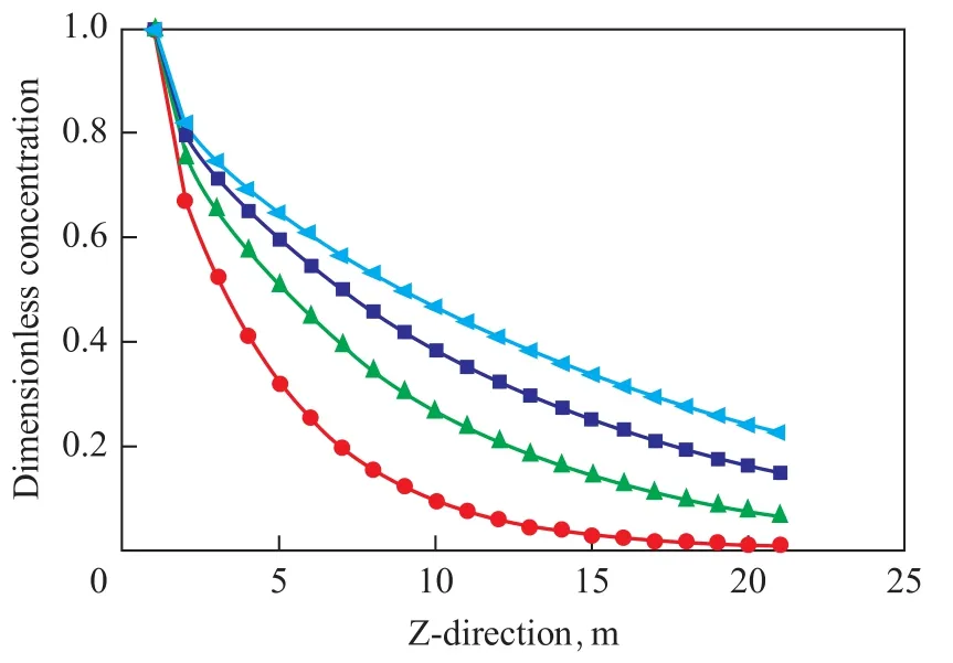
Figure 7 Axial dimensionless concentration distribution

Figure 8 Radial dimensionless concentration distribution
9 Conclusions
A mathematical model combined with the mass transfer resistance equation and the mass transfer differential equation was established. The simulation and experimental research on membrane absorption process of H2SMDEA-H2O system were also performed. The result indicated that hydrogen sulfide removal rate showed a positive dependence on the liquid concentration and gas pressure. However, the desulfurization rate decreased with an increasing gas flow rate. The in-tube concentration of hydrogen sulfide at the same point increased with the increase in gas velocity. The axial concentration of hydrogen sulfide decreased rapidly at the beginning, and the decrease saw a slowdown during the late half period. Hydrogen sulfide concentration dropped quickly in the radial direction, and the amplitude of decrease was gradually weakened in the radial direction with the increase of axial length due to the gradual reduction of hydrogen sulfide along the tube. The desulfurization rate under given operating conditions can be predicted by this model, and the theoretical basis for membrane module design can also be provided.
Acknowledgment:This work was financially supported by the National Natual Science Foundation of China (No.51176015).
[1] Liu Z D, Huang L M, Yang Z X, et al. Material corrosion factors of ground gathering line in high sulfurous environment[J]. Natural Gas Industry, 2004, 24(12): 122-123, 126(in Chinese)
[2] Cai P, Wang S L. Study on regeneration of MDEA solution using membrane distillation[J]. China Petroleum Processing and Petrochemical Technology, 2008(4): 45-51
[3] Li F, Sun G, Zhang Q, et al. Corrosion behavior and prevention of gas sweetening unit in natural gas processing plants[J]. Natural Gas Industry, 2009, 29(3): 104-106(in Chinese)
[4] Huang D L, Wang J Q, He G H, et al. Hollow fiber membrane contactor[J]. Membrane Science and Technology, 2005, 25(1): 63-68(in Chinese)
[5] Li H, Wang S L, Zhao H J, et al. Research on removal of sulfur from natural gas by membrane-based absorption[J]. Journal of Jiangsu Polytechnic University, 2007, 19(1): 45-48(in Chinese)
[6] Cai P, Wang S L, Sun C Q, et al. Research on desulfurization by natural gas multistep membrane absorption technology[J]. Applied Chemical Industry, 2008, 37(5): 475-477(in Chinese)
[7] Wang Z, Gong Y W, Yuan L, et al. Simulation for CO2absorbed in hollow fiber membrane absorber[J]. Journal of Chemical Industry and Engineering(China), 2003, 54(11): 1563-1568(in Chinese)
[8] Chen S, Zhang W D, Zhang Z T, et al. Simulation for acidic gas in membrane absorption process[J]. Journal of Beijing University of Chemical Technology(Natural Science Edition), 2005, 32(5): 14-18(in Chinese)
[9] Faiz R, Al-Marzouqi M. Mathematical modeling for the simultaneous absorption of CO2and H2S using MEA in hollow fiber membrane contactors[J]. J Membr Sci, 2009, 342(1/2): 269-278
[10] Hua C G, Kang G D, Jia J X, et al. Physical absorption of CO2using polyvinylidene fluoride membrane contactor at high pressure and mathematical simulation[J]. Chemical Journal of Chinese Universities 2013, 34(4): 906-912(in Chinese)
[11] Li C Y. An improved mathematical model of equilibrium solubility of H2S and CO2in H2S-CO2-MDEA-H2O system[J]. Petroleum Processing and Petrochemicals, 1998, 29(1): 49-53(in Chinese)
[12] Mason E A, Malinauskas A P. Gas Transport in Porous Media: The Dusty-Gas Model[M]. New York: Elsevier, 1983
[13] Alkhudhiri A, Darwish N, Hilal N. Membrane distillation: A comprehensive review[J]. Desalination, 2012, 287: 2-18
[14] Prasad R, Sirkar K K. Dispersion free solvent extraction with micro porous hollow-fiber modules[J]. AIChE J, 1988, 34(2): 177-188
[15] Han Y J, Wang S L. Experimental study on refinery gas desulfurization using gas-liquid membrane contactor[J]. China Petroleum Processing and Petrochemical Technology, 2009(3): 33-38
[16] Wang Shuli, Rao Yongchao, Wu Yuxian, et al. Experimental research on gas-liquid tow-phase spiral flow in horizontal pipe[J]. China Petroleum Processing and Petrochemical Technology, 2012, 14(3): 24-32
Received date: 2014-04-01; Accepted date: 2014-10-11.
Wang Shuli, Telephone: +86-519-83293890; E-mail: wsl@cczu.edu.cn.
- 中国炼油与石油化工的其它文章
- Comparative Studies on Low Noise Greases Operating under High Temperature Oxidation Conditions
- A Method for Crude Oil Selection and Blending Optimization Based on Improved Cuckoo Search Algorithm
- Experimental Research on Pore Structure and Gas Adsorption Characteristic of Deformed Coal
- Ni2P-MoS2/γ-Al2O3Catalyst for Deep Hydrodesulfurization via the Hydrogenation Reaction Pathway
- Effects of Airflow Field on Droplets Diameter inside the Corrugated Packing of a Rotating Packed Bed
- Synthesis of Phenyl Acetate from Phenol and Acetic Anhydride over Synthetic TS-1 Containing Template