Hybrid Simulation and Observation of Human Vertebral Endplate Morphology
É.Budyn,A.Bilagi,V.Subramanian,A.A.Espinoza Oríasand N.Inoue
1 Introduction
Low back pain that affects 50 to 70%of the adult population[Biering-Sorenson(1982)]is the second leading cause of disability in the US resulting in an annual health care cost of 80 billion dollars[Wilder and Pope(1996)].The exact origin of the pathology is still not well understood and researchers have hypothesized that the disc degeneration is a potential cause.Diverse mechanical[Videman,Nurminen,and Troup(1990);Hansson and Holm(1991);Fields,Sahli,Rodriguez,Ramos,Keaveny,and Lotz(2012);Inoue and Espinoza.Orías(2011)],genetics[Sambrook,MacGregor,and Spector(1994);Battie,Videman,and Gibbons(1995)]and systemic factors[Karupilla,Pentilla,and Karhunen(1994);Aufdermaur,Fehr,and Lesker(1980)]have been also linked to disc degeneration.However whether the source of the onset of the disc degeneration is caused by a biochemical factor[Antoniou,Steffen,Nelson,Winterbottom,Hollander,Poole,Aebi,and Alini(1996);Moore(2000);Rodriguez,Slichter,Acosta,Rodriguez-Soto,Burghardt,Majumdar,and Lotz(2011);Rodriguez,Rodriguez-Soto,Burghardt,Berven,Majumdar,and Lotz(2012)]alone or a biomechanical event[Moore(2000)]is still disputed.Some researchers using MRI have found that the changes in the nucleus pulposus alter the biomechanical environment of the vertebral segment[Fujiwara,Lim,An,Tanaka,Jeon,Andersson,and Haughton(2000)]and other researchers showed using CT scans of loaded and unloaded frozen samples that the mechanical injuries to the endplate cause reduced nutrition and hydration from the bone marrow to the disc[Fujiwara,An,Lim,and Haughton(2001)].
A vertebral segment is composed of the vertebral bone containing the bone marrow within its trabecular structures,the intervertebral disk(IVD)composed of a gelatinous nucleus pulposus(NP)surrounded by a stronger annulus fibrosus(AF),which is made of fibrocartilage and the endplate(EP)described as a peripheral subcutaneous bone part above the vertebral subchondral bone(BEP)[Singha and Singha(2012)]and a cartilaginous phase below the IVD(CEP).At an early embryonic stage in the axial skeleton development,the endplate is easily recognisable as a discrete entity located between the disc and the vertebral bone that remains cartilaginous during the subsequent ossification of the vertebrate[Taylor and Twomey(1993)].Before skeletal maturity is reached,small blood vessels penetrate the endplate and provide nutrition to the cartilage of the developing disc and the vertebral body.However at maturity,sparse blood supply in the outer layers of the annulus fibrosus remains and the mature disc then becomes avascular depending for its nutrition on the diffusion through the endplate of solutes dissolved in subchondral capillaries[Roberts,Menage,and Urban(1989)]of which buds emerge in trabecu-lar spaces to approach the cartilaginous endplates[Nachemson,Lewin,Maroudas,and Freeman(1970)]without penetrating it[Brodin(1955)]shown by histological studies of fluorescent and immunocytochemical that suggests a complex three dimensional interconnected network for the nutrient supply[Gruber,Ashraf,and Norton(2003)].
Despite the fact that present network of micro-cracks is usually not apparent,disc degeneration has been linked to changes of the supply of solutes following disruptions to the blood supply such as atherosclerosis of major arteries[Kurunlahti,Tervonen,Vanharanta,Ilkko,and Suramo(1999);Kauppila(1997)]or direct alterations to the endplate[Urban,Smith,and Fairbank(2004);Roberts,Urban,Evans,and Eisenstein(1996);Fujiwara,Lim,An,Tanaka,Jeon,Andersson,and Haughton(2000)].Aging changes in the cartilaginous endplate composition and structure have also been observed showing a progressive calcification by an unknown mechanism and thining[Bernick and Caillet(1982)]impairing the nutrition exchanges.However,it is not clear whether the loss of nutrient supply due to the endplate calcifications and adverse bone formation[Bernick and Caillet(1982);Oda,Tanaka,and Tsuzuki(1983)]causes the disc degeneration or whether a degenerative disc precedes the endplate modifications by altering its mechanical environment[Urban,Smith,and Fairbank(2004);Fields,Sahli,Rodriguez,Ramos,Keaveny,and Lotz(2012)].The cartilage endplate solute transport is similar to what is seen in articular cartilage[Roberts,Urban,Evans,and Eisenstein(1996)]and is influenced by two major factors:the proportion vascular contacts at the endplate and the steric properties of the solute involved affecting cell viability and homeostasis[Horner and Urban(2001);Bibby,Fairbank,and Urban(2002);Gruber and Hanley(1998)].Traumatic mechanical injuries or congenital weaknesses can also separate the endplate from its subjacent bone[Natarajan,Ke,and Andersson(1994);Hulme,Boyd,and Ferguson(2007)]or cause micro failures that lead to bulging calcifications in the disc and loss of hydration,uneven load distribution[Gruber,Ashraf,and Norton(2003)]and excessive deformations leading in extreme cases to extrusions in the vertebral body like Schmorl nodes[Schmorl and Junghanns(1971)].
The first characterizations of the endplate morphology and its degeneration over multiple scales have been performed using clinical tools such as CT scan[Fujiwara,An,Lim,and Haughton(2001)],micro CT scan[Noshchenko,Plaseied,Patel,Burger,Baldini,and Yun(2012);Rodriguez,Rodriguez-Soto,Burghardt,Berven,Majumdar,and Lotz(2012);Wang,Battie,Boyd,and Videman(2011)]and MRI[Fujiwara,Lim,An,Tanaka,Jeon,Andersson,and Haughton(2000)].At the macro scale,biomechanical tests coupled to MRI measured the effects of disc degeneration and facet joint osteoarthritis on lumbar spine flexibility,extension,lateral bending and axial rotations in female and male cadaveric vertebrae.Such tests showed gender differences with higher subchondral sclerosis and disc degeneration in axial rotation that were also correlated to reduced flexibility particularly in male[Fujiwara,Lim,An,Tanaka,Jeon,Andersson,and Haughton(2000)].
For efficient inexpensive high resolution imaging of the human vertebral endplate morphology,a protocol is presented to prepare fresh millimetric samples harvested in the central region of cranial location in cadaver samples from human donors of age ranging from 15 to 79 in Sections 2.1 and 2.2.The presented procedure mostly relies on man hour and does not require any heavy equipment time or investment.The central region was targeted for its proximity to the NP where the first signs of degeneration related to the endplate are known to onset in teenage years.Panoramic views of the endplate obtained by image reconstruction using direct Reflected Light Microscopy(RLM)and Transmitted Light Microscopy(TLM)after histological staining are presented.Morphometric characterisation of the human endplate is studied in the coronal,sagittal and transverse planes to observe macroscropic thickness and microscopic structural changes such as visible cracks and to identify the cells spatial distribution by a Fast Fourier Transform algorithm in Section 2.3.Qualitative local stiffness measurements were performed by nanoindentation.Discussion and conclusions are given in the final section 4.
2 Materials and Methods
The vertebral specimens were harvested from frozen L2-L3 vertebral motion segments from five human donors of age spanning 15 to 79(average of 50.8)as shown in Table 1.
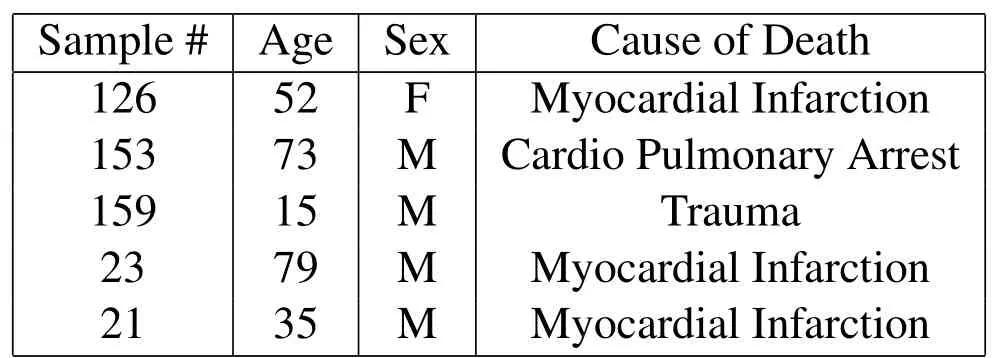
Table 1:Patient history list of the harvested samples
The samples were harvested from the central region of human vertebrae stripped from muscle and cartilage attachments.Once the vertebral body was clean of all tissues,the pedicles and spinous processes were also removed with a low speed saw(Isomet Low Speed saw,Buehler,Lake Bluff IL).The vertebral motion segment was then dissected and separated by levels.Large specimens were cut and fixed in 10%buffered formalin for seven days before being sectioned again into smaller cubic samples of nominal dimensions 5×5×5mmcontaining the endplate tissue surrounded by its attached subchondral bone beneath and its IVD cartilage above it.The vertebral endplate microstructure was then polished using fine grain abrasives.Thicker samples were observed under RLM and thin tissue slices were studied under TLM for measurements at the tissue and cell scales.
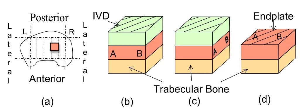
Figure 1:(a)Location of the harvested endplate samples in a schematic top view of a human vertebra and schematic sample structure in the(b)coronal,(c)sagittal and(d)transverse planes.
2.1 RLM observations of vertebral samples:
The specimens were first ground for one minute using a Carbimet 2 600 grit sheet on a polisher(Polimet Polisher,Buehler,Lake Bluff IL)and fixed with tape and glue onto a known weight steel cylinder sample holder(348.8g).The samples were then polished to a final 0.05µmroughness using four abrasive suspensions of increasingly finer grades 3µm,1µm,and 0.25µmdiamond polishing paste.The last polishing was achieved with a suspension of 0.05µmgamma deagglomerated alumina.Each polishing was performed on different corresponding cloths to avoid cross-contamination.Between each subsequent grinding and polishing,the specimens were washed in running warm water to remove the particulate debris from the previous operation.Specimens were finally cleansed with ethanol and airblow dried.The dried samples were observed using RLM(Nikon Instruments Inc,Melville NY)at the magnifications 2.5x and 10x.
Three characteristic orthogonal orientations in the coronal,sagittal and transverse planes were observed.For each plane,adjacent images of the endplate at 10x magnification(Nikon Instruments Inc,Melville,NY)are coalaesced using Photoshot DXM 1200.For each image of a sequence,three different pictures focused on the distinct morphological layers(IVD cartilage,endplate or subchondral bone)were captured.Since the images were not always in the same plane,the stack of pictures at the different focal lengths were recombined into one single in-focus layer using the image processing program Helicon Focus 4.0.Following this image post-processing,a complete panorama of the endplate region was prepared.For the transverse plane image sequence of the endplate that was reconstructed by the previously described procedure,slow polishing was applied to ensure that the endplate was not completely consumed but that the cartilage of the IVD was removed.For the transverse view specimens,to facilitate manual handling,these samples were potted in PMMA.
Qualitative local mechanical characterisation:For two vertebral samples,the local Young’s moduli were measured by nanoindentation(MTS Nano-XP)at École Centrale Paris on the sagittal and coronal sections in dry conditions and ambient temperature using a Berkovich tip at a constant strain rate(5.10−2s−1)at 20 locations in the cartilaginous endplate and 5 in the neighbouring bone for comparison.The elastic modulus was determined from the indentation load-displacement curve[Oliver and Pharr(1992)].During the tip penetration,variation of the Y-oung’s moduli(due to superimposed continuous nano-oscillation of the tip in the dynamics mode CSM)for each test was of the order of±1GPa[Hoc,Henry,Verdier,Aubry,Sedel,and Meunier(2006)].However because the specimens had been fixed in formalin,the biomaterial integrity and mechanical properties were different from fresh tissues due to additional collagen cross-lining.Therefore qualitative hardness ratio estimations were only obtained indicating a four-fold order of stiffness magnitude between the cartilaginous endplate(2GPa)and the neighbouring bone including the osseous endplate phase(6-8GPa),which was in agreement with the literature[Hoffler,Moore,Kpzloff,Zysset,Brown,and Goldstein(2000)].The endplate’s dual nature exhibiting significantly lower modulus in the cartilaginous phase confirmed its viscoelastic nature in this partition as indentation points could not be identified after the test compared to indents in the osseous phase.
2.2 TLM observations of vertebral samples:
Information about cell populations present in the vertebral endplate was studied by histological analyses.Two types of fixed endplate specimens were prepared using staining protocols for osseous tissues for observations under TLM that were either undecalcified or decalcified.The samples were observed at the magnification 10x,20x and 100x.
Undecalcified bone samples:The undecalcified specimens were dehydrated using solutions of 70%,90%and absolute alcohol(74◦OP methylated spirit)for 24 hours each.Traces of alcohol remaining in the specimens were rinsed off with xylene solution.To harden the three tissue types,the samples required embedding into a polymer.The polymer was prepared using stock catalysed methyl methacrylate monomer mixed in equal volumes with 5%sodium hydroxide.The mixture was washed three times with distilled water and then 1gof benzoyl peroxide was added to each 100cm3of monomer and then filtered through calcium chloride.The stock catalysed monomer and polymer were then mixed and stored for 24 hours at 0-4◦C.The tissue samples were then in filtrated with the partially polymerised methacrylate for 24 hours each at 4◦Cin plastic molds that allow shrinkage and cured at 37◦C in a water bath for one to three days.These undecalcified samples were first ground on the polisher(Polimet,Buhler,Lake Bluff IL)using sandpaper of 180,240,320,400,600,800 grit sizes and then cut by microtome into 100µmthin slices that are fixed on glass slides.The slides were finally stained in 100mlalcoholic basic fuchsin and toluidine blue stain for 1 hour and 30 minutes before washing with a 4%HCl solution.
Decalcified bone samples:The other samples were decalcified using a mixed solution of equal volumes of 8%hydrochloric acid and 8%formic acid for 20 times the volume of the specimens for three days until complete decalcification.To neutralise acid traces,the specimens were first rinsed with water and then transferred to an ammonia solution(5 drops per 100ml)up to 24 hours before being rinsed in running water.The samples were finally embedded in 100% paraffin and cured at 37◦Cin a water bath for one to three days and sectioned with a Micron HM325 microtome(Southeast Pathology Instrument Service,SC)into 7µm thick slices fixed on glass slides.In order to stain the slices with H&E[World(2007)],the samples were first de-paraffinised through 2 changes of xylene of 10 minutes each.The samples were then rinsed in 2 changes of absolute alcohol of 5 minutes each before being rinsed in solutions of 95%alcohol for 2 minutes and 70%alcohol for 2 minutes.The slices were finally washed in distilled water and stained in H&E solution for 8 minutes.
2.3 FFT analysis of the chondrocyte orientations:
To obtain information at the cell scale,a two-dimensional Fourier analysis of the histology images has been employed in this study to estimate the orientation of the chondrocytes’nuclei in the vertebral endplates decalcified samples in images of formatted dimensions 256 x 256 pixels that defined aN2pixels region of interest(ROI).This technique was extended from an optical Fourier analysis to a digital Fourier transform using a Fast Fourier Transform(FFT)algorithm.The region of interest in the decalcified tissue images was selected using Adobe Photoshop[Lawson and Brabant(2007)]and NIH ImageJ[Reinking(2007)].In the images,the chondrocyte nuclei and their surrounding cytoplasm were assigned different RGB(Red Green Blue)values in Figs.21(a,e,i).The grey levels of the images,notedg(x,y)of pixel(x,y),were first rescaled and the images were converted into 8-bit images shown in Figs.21(b,f,j).The FFT calculated the normalized power spec-trum notedF(n,m)of the image frequency domain as follows:

wherenandmare the spatial frequencies corresponding to thexandyCartesian axes.
Inversely the spatial image,g(x,y),can be reconstructed from the Fourier image,F(n,m)through the inverse Fourier transform:

In the two-dimensional FFT analysis,location information of an individual element was extinguished and,as a result,all image information was gathered around an origin of spectrum field(center of the spectrum field)(Figs.21(c,g,k)).The preferred orientation in the image was represented by a peak in the power spectrum(F(n,m)×F(n,m))around the origin of the frequency transform[Konttinen,Pyka,and Kangas(2007)].The power spectrum,F(n,m),can be separated as follows:

The power spectrum in the Cartesian system could then be easily reformulated in the polar system,notedP(r,θ),using a linear interpolation to allow an easy and fast analysis of the directionality.Replacingnbyrcos(θ)and m byr sin(θ),the power spectrum becomes:

To quantify the intensity of the orientation,the power spectrum in the polar system can be represented by a texture operator,notedwhereθvaries from 1oto 180ofor angle discretization purposes andrvaries from 0 toN/2.The power spectrum is then calculated within fan-shaped segments corresponding to one degree angle of orientation increment.This decomposition leads to the definition of an intensity function,notedF(θ),that is the summation of the power spectrum within a fan-shaped area at the orientation of angleθas follows:

and a distribution function,notedf(θ),as follows:

In these images,the FFT analysis computes the orientations and angles of the cells shown in Figs.21(c,g,k)as a universal point distribution and(d,h,l)as a probability distribution function[Chao,Inoue,Elias,and Frassica(2000);Jones,Inoue,Tis,McCarthy,McHale,and Chao(2005);Inoue,Sakakida,Yamashita,Hirai,and Katayama(1987)].The intensity of an orientationθcorresponds to a random orientation when close to zero and completely aligned to a specific orientation when close to one.
The detailed steps of the FFT image processing algorithm are illustrated in Fig.2.The FFT algorithm had been first validated using a binary image showing two regions of different pattern orientations[Guerin and Elliott(2006)].
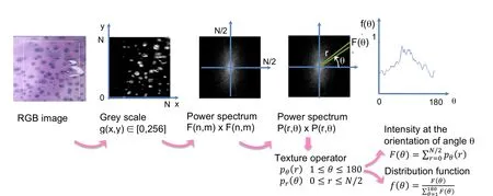
Figure 2:FFT image processing algorithm.
3 Results
3.1 Reflective Light Microscopy observations:
Schematic views of three characteristic orthogonal orientations in the coronal,sagittal and transverse planes are shown in Fig.1.
3.1.1Coronal plane observation of human vertebral endplate:
The location where the specimens were harvested is shown in Fig.1.All the specimens were taken near the right lateral edge of L3 vertebral body.After successive sagittal cuts of center-cut macroscopic vertebra specimens,the image sequence of the coronal plane of two of the five millimetric samples that were reconstructed with high resolution images are shown in Figs.4 and 5.

Figure 3:Schematic showing the paths of the different image sequences in the coronal plane representing the three morphological layers of the vertebral segments for the specimens:(a)TS21,(b)TS23,(c)TS126,TS153 and TS159.
In the coronal plane,the subchondral bone Haversian microstructure with few distinct lamellar osteonal structures is visible beneath the endplate in Figs.4-5.The presence of few osteons may indicate low remodeling in the case the vertebral endplate undergoes small mechanical loading as the IVD carries most of the load.The trabecular bone is immediately adjacent to the trabecular bone in Figs.4.The endplate region appears as a darker region above the cortical bone layer and beneath the IVD at a particularly recognizable tidemark in Fig.5.Elliptical lacunae of varying densities are observed in the endplate and osteonal lacunae are seen in the subchondral bone in Fig.4.
3.1.2Sagittal plane observation of human vertebral endplate:
The samples for the sagittal view were taken near the right lateral edge of L3 vertebral body.Fig.6 shows the path location of the different image sequences in the sagittal plane that also display three characteristic morphological layers.High resolution image sequences are shown in Figs.7-9.
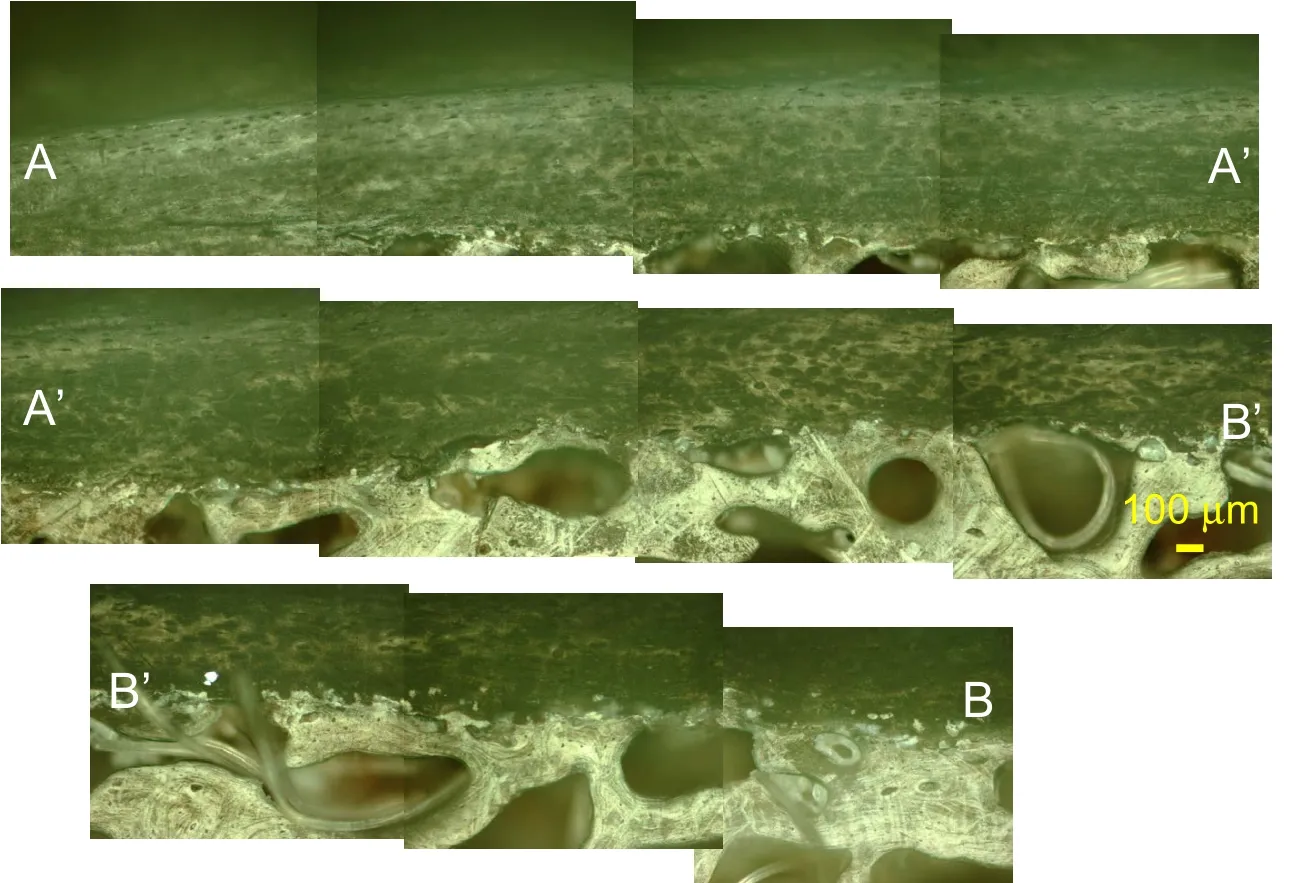
Figure 4:RLM observation of the coronal view of human vertebra sample TS23 at 100x magnification following the path of Figure.3(b).
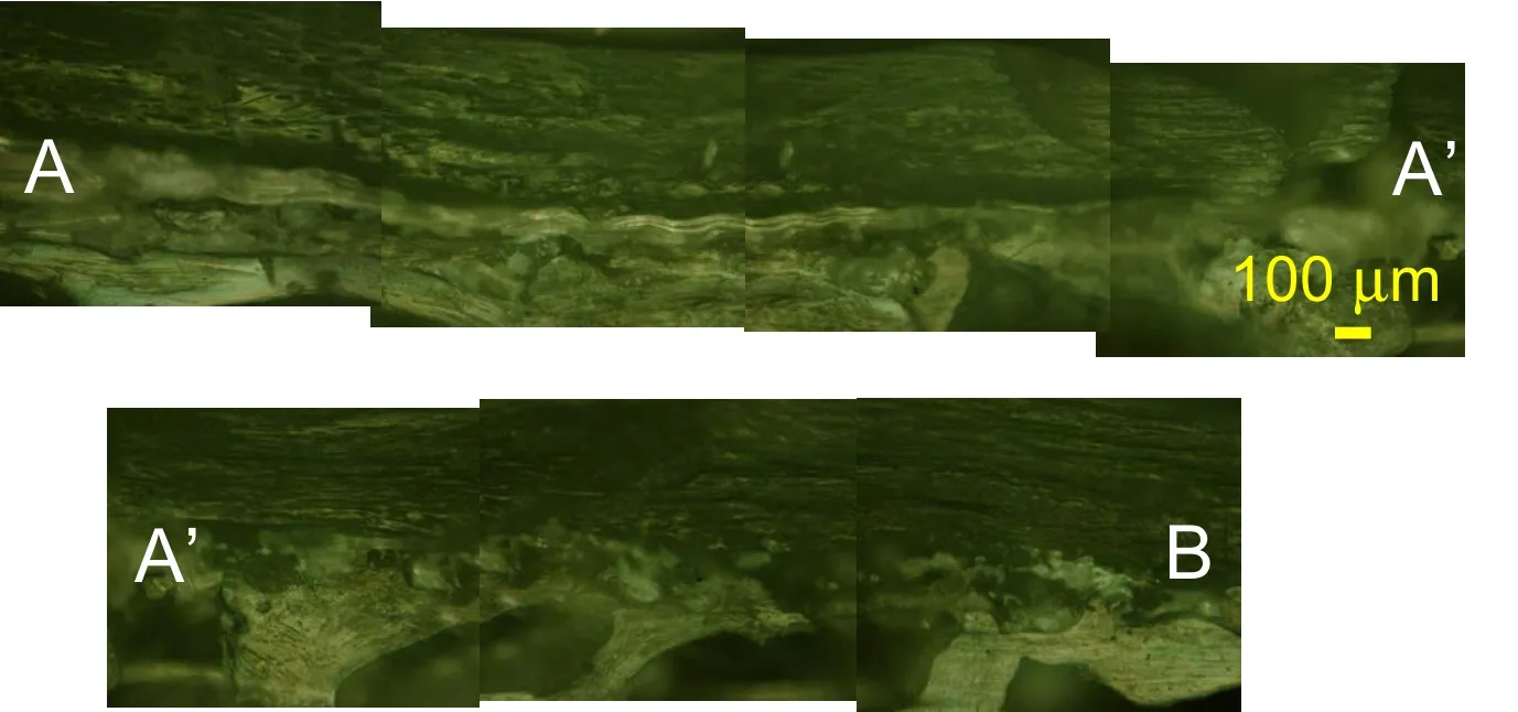
Figure 5:RLM observation of the coronal view of a vertebra sample TS153 at 100x magnification following the path of Figure.3(c).

Figure 6:Schematic showing the paths of the different image sequences in the sagittal plane representing the three morphological layers of the vertebral segments for the specimens:(a)TS21,(b)TS23 and TS159,(c)TS126 and TS153.
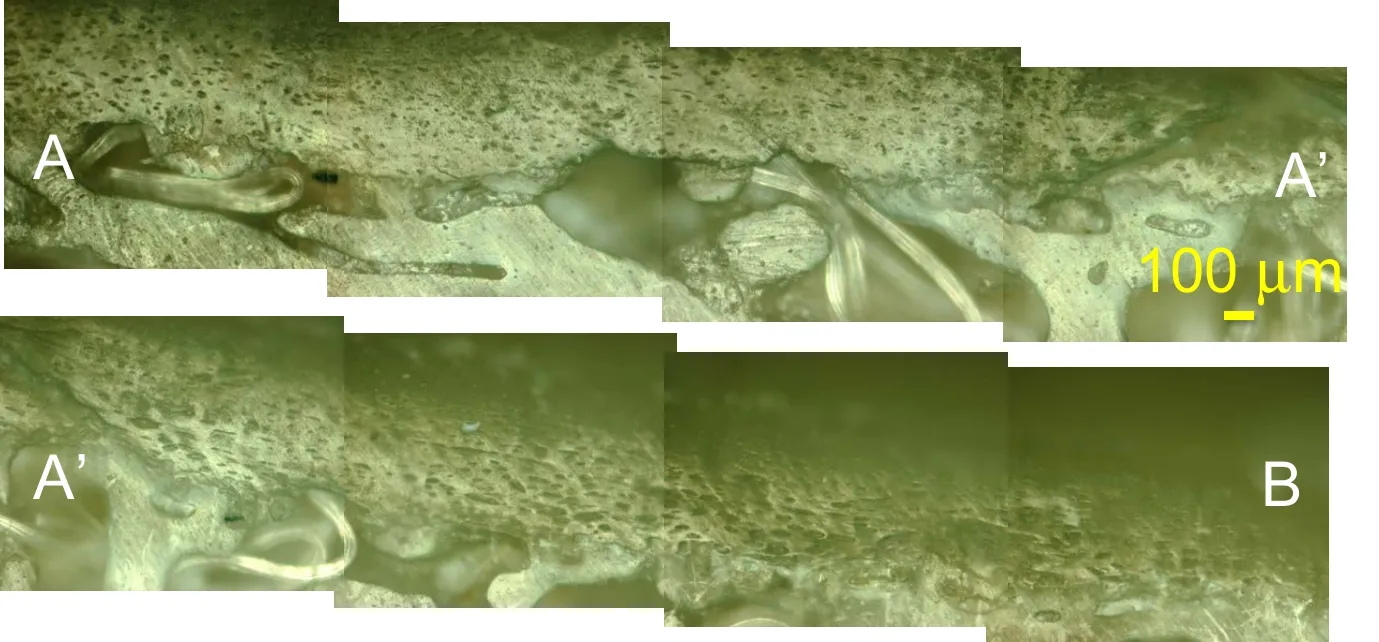
Figure 7:RLM observation of the sagittal view of human vertebra sample TS23 at 100x magnification following the path of Figure.6(b).
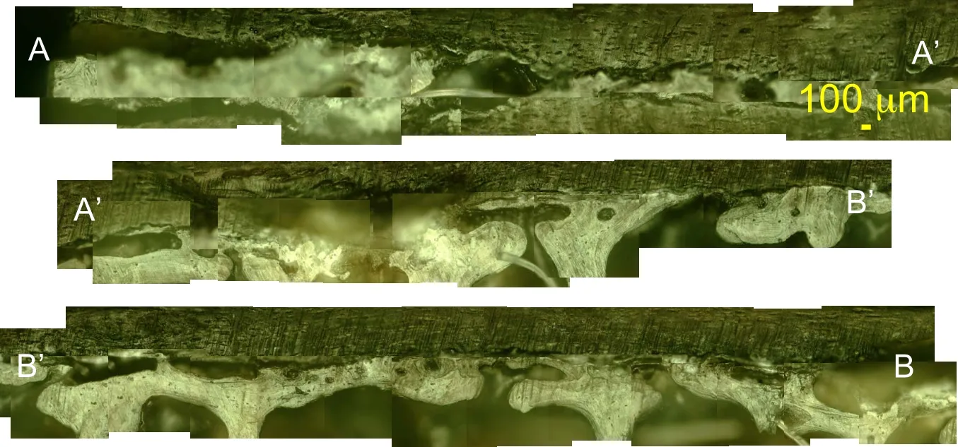
Figure 8:RLM observation of the sagittal view of human vertebra sample TS126 at 100x magnification following the path of Figure 6(c).
In the sagittal view,a transition region commonly known as tidemark is observed above a lighter region of the osteonal like bone tissue and beneath a darker region which is the cartilaginous endplate in Figs.7.8 and 9.
From top to bottom of the images, the identical morphological layout is seen in both sagittal and coronal planes with the IVD cartilage,the endplate and the subchodral and trabecular bone.In the endplate region,a dense population of cells,mostly likely chondrocytes are seen.
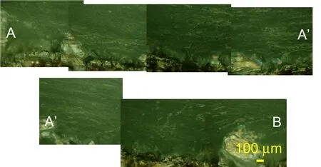
Figure 9:RLM observation of the sagittal view of human vertebra sample TS159 at 100x magnification following the path of Figure.6(b).
3.1.3Transverse plane observation of human vertebral endplate:

Figure 10:Schematic showing the paths of the different image sequences in the transverse plane representing the three morphological layers of the vertebral segments for the specimens:(a)TS21,(b)TS23,(c)TS126,(d)TS153 and(e)TS 159.
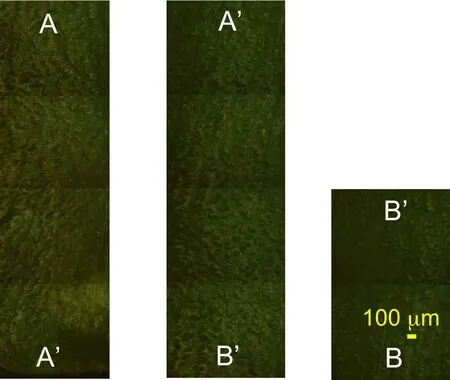
Figure 11:RLM observation of the transverse view of a vertebra sample TS23 at 100x magnification following the path of Figure.10(b).
Fig.10 shows the paths followed by the five panoramic image sequences reconstructing the transverse view of the vertebral samples.The two of the five RLM observations of the transverse plane are shown in Figs.11-12.Fig.12 shows the three types of microstructures in the transverse plane,from left to right:the subchondral bone,the endplate and the IVD cartilage.In Fig.12,cloudy white spots indicating calcium deposits are seen in the right lateral side of both image series.Dense populations of elliptical lacunae are seen in the endplate region in particular in Fig.11without any specific orientation revealed by FFT analysis.
3.2 Endplate Thickness Measurement
The endplate thickness was measured in the RLM panoramic observations in Figs.4-9.In each relevant single image,the endplate thickness was measured at 3 locations.The measurements were taken for 32 microscopic single observations of 4 different samples at standardised locations for each field of view:25%,50%and 75%as shown in Figure 13(a).
For the TS23 sample,additional measurements were possible in the TLM observations in the undecalcified and decalcified specimens in the coronal,the sagittal and the median planes shown in Figs.16 and 18-20 and given in Table 2.The median plane was defined as a plane located at 45◦between the sagittal and the coronal planes.The average endplate thickness was calculated as followed:

Figure 12:RLM observation of the transverse view of a vertebra sample TS126 at 100x magnification following the path of Figure.10(c).
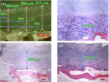
Figure 13:Measurements of vertebral endplate thickness in TS23 sample(a)at 3 locations in a single RLM observation in the coronal plane at 100x magnification,and in TLM observations of decalcified samples at 100x magnification in the(b)coronal,c)sagittal and d)median planes.
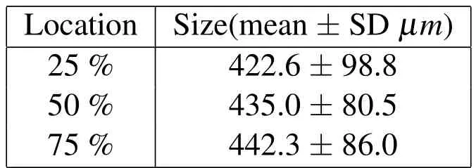
Table 2:Endplate thickness mean and standard deviations
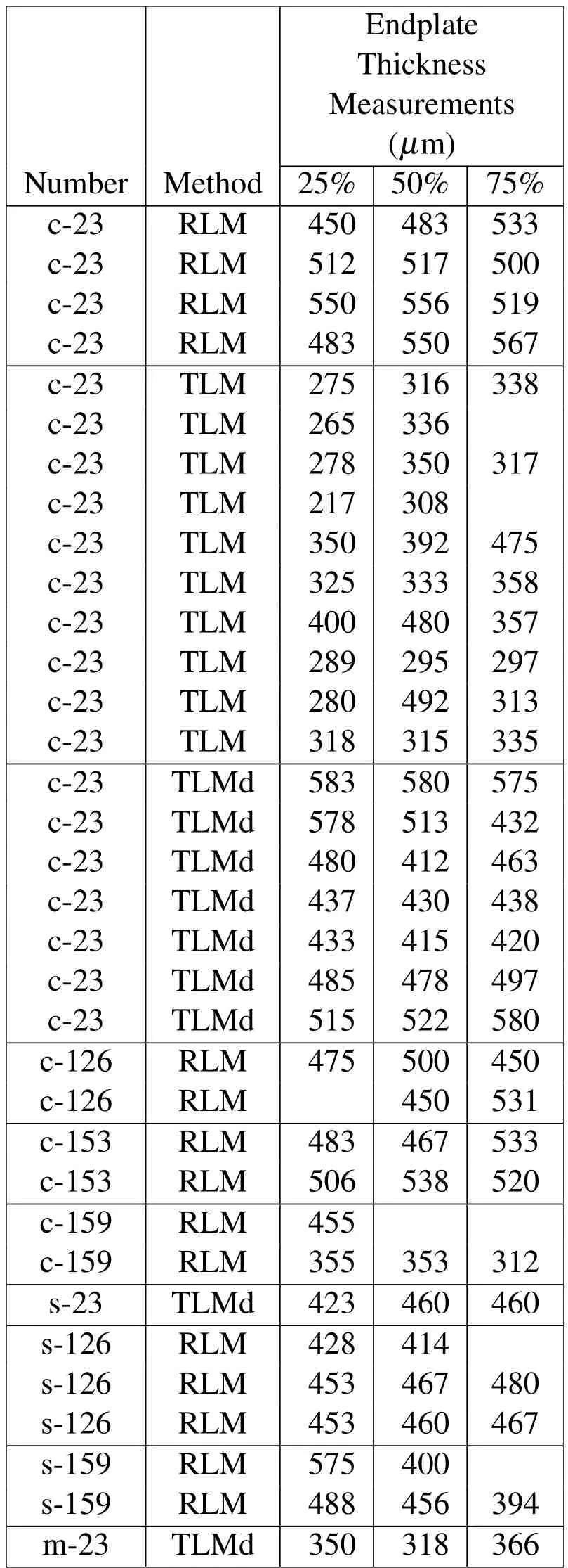
Table 3:Endplate Thickness Measurements in RLM and TLM observations.TLMd designates TLM for decalcified samples.We note:c=Coronal,s=Sagittal,m=Median.

wherenR,nTandnTdare the number of endplate thickness measurements,tj,in the microscopic observations using either RLM or TLM for undecalcified and decalcified samples.
The average endplate thickness,,of our samples was found to be 432.9µmwith a standard deviation of 89.3µmshown in Table 3.
3.3 Transmission Light Microscopy observations:
The vertebral endplate specimens were also stained for histology analysis and observed in the coronal,sagittal and median planes using Transmission Light Microscopy(Microphot-FXA,Nikon Instruments Inc,Melville NY).
3.3.1TLM observations of coronal plane of human vertebral endplate:
The human vertebral samples were first prepared as undecalcified thin slices mounted on slides for TLM observations and were stained with basic fuchsin and toluidine blue in order to identify cell nuclei in blue and the different tissues is various shades of pink and purple.In particular toluidine blue makes it possible to visualise the bony endplate[Compston,Vedi,and Webb(1985)].
Figures 14(a)and(c)show the coronal view of a TS23 undecalcified sample harvested in L2-L3 vertebral segment that display an intact endplate at magnifications 10x and 100x.However in Figure 14(a),the left hand side exhibits some cartilaginous endplate thining compared to the right hand side[Kakitsubata,Theodorou,Theodorou,Trudell,Clopton,and Resnick(2002)]and some possible sclerotic metastatic deposit at the interface between the bony and cartilaginous endplate where a darker purple shade is observed[Resnick and Niwayama(1978)].On the other hand,Figure 14(b)and(d)display a sample harvested at another location in the same vertebra that contains a disc disruption and fracture damage at magnifications 10x and 100x.The crack appears to originate fractured the entire endplate both cartilaginous and bony regions down to the subchondral bone.The crack has originated in the IVD cartilage[Dudli,Haschtmann,and Ferguson(2012)].
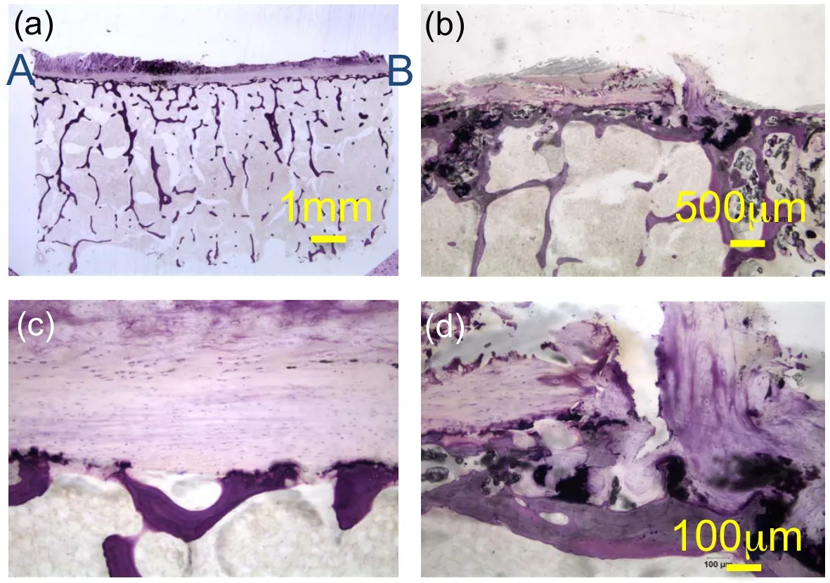
Figure 14:TLM observations of the coronal view of undecalcified TS23 vertebral samples stained with basic fuchsin and toluidine blue:a)at 10x and c)at 100x magnifications showing an intact endplate region,b)at 20x and d)at 100x magnifications showing a micro fracture in the endplate.

Figure 15:(a)Location of the harvested TS23 undecalcified sample in a schematic top view of the human vertebra in the L2-L3 segment,(b)schematic representation of the 3 material phases present in the coronal section and(c)schematic views of the coronal plane indicating the path of the endplate image sequence shown in Figure.16.
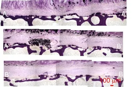
Figure 16:TLM observation of the coronal view image series of undecalcified sample TS23 stained with basic fuchsin and toluidine blue at 100x magnification that displays a dark localised region and thinning in the CEP.
To improve the lower resolution of the endplate observation in Figure 14(a),a high resolution image mosaic following the endplate is reconstructed in Figure 16.The path of the image series in the coronal plane is shown in Fig.15(c).A dark stain,possibly a sclerotic metastatic deposit,is observed in the endplate region between A’and B’[Resnick and Niwayama(1978)]at the interface between the bony and cartilaginous endplate.In the AA’section,thining of the CEP[Kakitsubata,Theodorou,Theodorou,Trudell,Clopton,and Resnick(2002)]is also observed in Figure 16.Basic fuchsin and toluidine blue stained slides show elongated cells possibliy AF cells or chondrocytes[Nosikova,Santerre,M.Grynpas,G.Gibson,and Kandel(2012);Hayes,Hughes,Ralphs,and Caterson(2011);Pattappa,Li,Peroglio,Wismer,Alini,and Grad(2012)]and fibroblasts in the CEP,the intermediate region between subchondral bone and pure cartilage of the IVD.In Fig.16 sample endplate displays a near uniform thickness of 362µm.On the upper part of the subchondral cortical shell,a darker purple shade is seen and usually indicates a higher degree of mineralization[Compston,Vedi,and Webb(1985)]called the bony endplate region.In Fig.16 this region appears continuous throughout the sample.Since the slides are not stained for bone marrow the voids in the trabecular region appear clear.The fibrous structure of the IVD is shown in the middle of the section AA’where the fibers of type II collagen insert themselves into the cartilagi-nous endplate in a manner consistent with the observations by Wade et al.[Wade,Robertson,and Broom(2012)].

Figure 17:(a)Schematic top view of a human vertebra,schematic representations of the harvested vertebra samples(b)in the coronal direction and(c)Schematic view of the vertebra sample TS23.
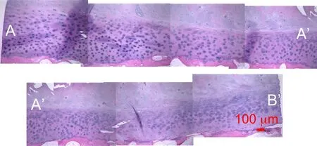
Figure 18:TLM observation of the coronal panoramic view of a decalcified vertebral endplate TS23 sample at 100x magnification stained with H&E and showing a micro fracture in the CEP.
The decalcified vertebral samples stained with H&E are shown in Fig.??at low magmifications 10x and 20x.The cartilaginous endplate appears in a slightly darker purple shade than the IVD tissue above and is sitting on the subchondral cortical shell that appears stained in pink.The bone marrow appears in light pink.The subchondral shell seems continuous throughout the length of the sample.Figure 18 shows a reconstructed coronal panoramic view of the endplate region and that appears mostly healthy and of uniform thickness of 479µm.Osteocyte lacunae can be seen in the subchondral shell.The path of the image series is shown in Fig.17(c).The endplate region contains dense circular and elliptical shaped cells which show a phenotype similar to chondrocytes[Nosikova,Santerre,M.Grynpas,G.Gibson,and Kandel(2012);Hayes,Hughes,Ralphs,and Caterson(2011);Pattappa,Li,Peroglio,Wismer,Alini,and Grad(2012)],which is in agreement with the hypothesis that the endplate contains a cartilaginous phase[Nosikova,Santerre,M.Grynpas,G.Gibson,and Kandel(2012)].The cartilage layer in the IVD above the endplate shows scattered round cells which are presumed to be chondrocytes.The distinct arrangements of the cartilage of the IVD and endplate are marked by different chondrocyte populations in the two regions that are either purple in the endplate or bluish in the IVD[Hayes,Hughes,Ralphs,and Caterson(2011);Pattappa,Li,Peroglio,Wismer,Alini,and Grad(2012);Nosikova,Santerre,M.Grynpas,G.Gibson,and Kandel(2012)].The presence of two different types of cartilages either rich in chondrocytes in the endplate(CEP)[Mwale,Roughley,and Antoniou(2004);Rufai,M.Benjamin,and Ralphs(1995)]or sparse in chondrocytes in the IVD(possibly AF or NP region)is clearly shown in Figure 18.A micro fracture in dark purple is also seen in the middle of section A’B’at the interface between the cartilaginous endplate and the IVD[Dudli,Haschtmann,and Ferguson(2012)].
3.3.2TLM observations of sagittal plane of human vertebral endplate:
Two sagittal cut of vertebral specimens have been prepared either undecalcified and stained with basic fuchsin and toluidine blue or decalcified and stained with H&E solution.The sagittal view of the basic fuchsin and toluidine blue stained undecalcified vertebral endplate sample is shown at two different magnifications in Fig.19(a)at magnification 10x,with a zoom in the vicinity of an anomaly in Fig.19(b)at 100x magnification.The endplate thickness is uniform throughout its section except in the left hand side where disrupted tissue is observed.The subchondral bone plate seems nearly uniform throughout the length of the specimen and the upper darker purple layer show the bony endplate.In Fig.19(b),the disruption in the endplate seems to pass through the entire endplate region,CEP and bone phase,penetrating into the marrow in Fig.19(b).This could show the initiation of the formation of a Schmorl node[Kakitsubata,Theodorou,Theodorou,Trudell,Clopton,and Resnick(2002)].At higher magnification,elongated cells that could be fibroblasts,chondrocytes or AF cells,are seen in the endplate.
The sagittal view of the decalcified vertebral slide stained with H&E is shown in Figure 19.Due to their soft nature the IVD cartilage and the cartilaginous enplate on the right hand side of the sample have detached.The cartilaginous endplate region appears in a darker purplish shade beneath the IVD cartilage and above the subchondral bone.In the cartilaginous endplate,possible chondrocytes are randomly distributed at 100x magnification.Since this slide has not been stained for bone marrow,this phase apears clear within the trabecular bone.The subchon-dral bone shell is stained in pink and appears continuous throughout the length of the specimen.In the left hand side and in the middle of the vertebral sample in Fig.19(c),the endplate has been invaded by cartilaginous tissue that is disrupting the subchondral shell and entering the vertebral bone marrow.
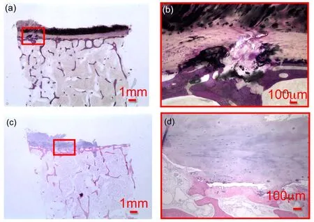
Figure 19:TLM observations of the sagittal view of undecalcified TS23 sample at a)10x and b)100x showing the initiation of a Schmorl node.TLM observations of the sagittal view of decalcified vertebral endplate TS23 sample at c)10x and d)100x showing endplate corrosion.
3.3.3TLM observations of median plane of human vertebral endplate:
Figure 20 shows the image of vertebral specimens observed in the median plane located between the sagittal and the coronal planes.The sample are decalcified and stained with H&E.Figures 20(a)and(b)show a lesion in the endplate at low and high magnification.In the left lateral end of the sample,the CEP has been invaded by cartilaginous tissue and the bony endplate is corroded. The cartilaginous endplate is penetrating through the bony endplate and is disrupting the subchondral shell[Kakitsubata,Theodorou,Theodorou,Trudell,Clopton,and Resnick(2002)].In contrast Figure 20(c)shows a healthy endplate where presumed chondrocytes are stained in blue throughout the tissue.
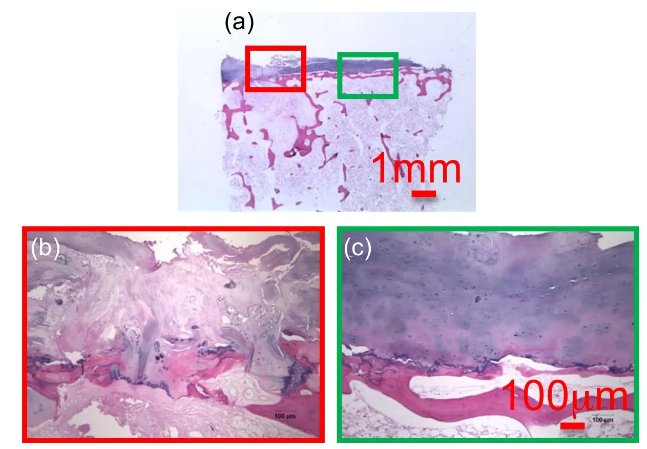
Figure 20:Medial Plane view of decalcifed vertebral endplate TS23 sample at a)10x,b)and c)100x magini fi cation showing a corroded region of the CEP and a healthy region respectively.
3.4 Determination of the orientations of chondrocytes in decalcified endplate specimens using FFT algorithm:
At the cell scale,the morphometric properties of the cell distribution in the human vertebral endplate are measured in selected images of decalcified endplate TS23 healthy samples.The cell orientations are calculated by the FFT analysis described in Section 2.3 and are shown in Figs.21(c)(g)and(k)as universal point distributions in the coronal,the sagittal and the median planes and as probability distribution functions in Figs.21(d),(h)and(l)where the peak orientations of the chondrocytes are shown.The results of the FFT analysis are summarised in Table 4.The chondrocytes in the carlilaginous endplate in the coronal plane were found to display a slight tendency to orientate along the horizontal direction in Fig.21(c)and(d)with an average angle of 1.9o(±15.3)(Table4)in response to possible vertical and bending compressions[Farnum and J.Wilson(2011)].In the sagittal plane,the chondrocytes displayed no preferred orientation in Figs.21(g)and(h)with an average angle of 0.4o(±13.2)(Table 4)as possible response to shear and less frequent bending stimulations in the sagittal plane[Korhonen,Julkunen,Wilson,and Herzog(2008)].In the median plane,the chondrocytes displayed no preferred orientation in Figs.21(k)and(l)with average angle of 3.1o(±8.3)(Table 4).The absence of preferential orientation in the sagittal and median planes,suggesting round-shaped chondrocytes transversely to the coranal plane may suggest random orientation of flattened cells as possible response to a uniform vertical compression in the transverse plane[Korhonen,Julkunen,Wilson,and Herzog(2008)].
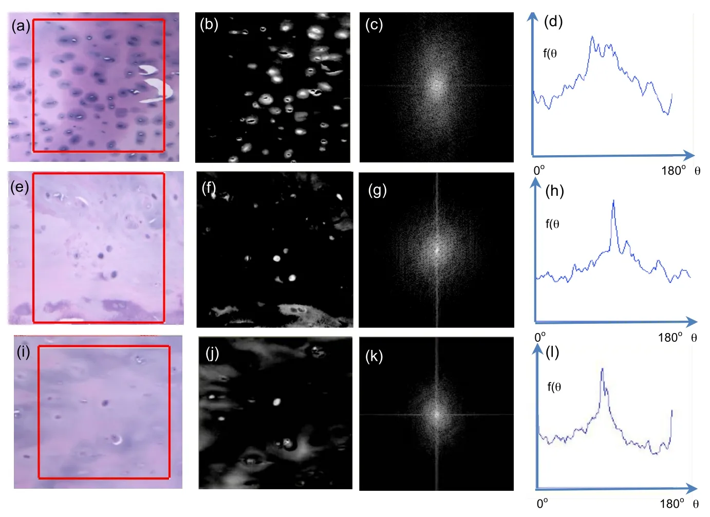
Figure 21:(a)TLM observation of decalcified endplate TS23 specimen in the coronal plane,(b)reverse greyscale image of the observed sample,(c)angle distribution of the chondrocyte’s orientations,(d)continuous probability distribution of the chondrocyte’s orientations in the endplate sample.(e)TLM observation of decalcified endplate TS23 specimen in the sagittal plane,(f)reverse greyscale image of the observed sample,(g)angle distribution of the chondrocyte’s orientations,(h)continuous probability distribution of the chondrocyte’s orientations.(i)TLM observation of decalcified endplate TS23 specimen in the median plane,(j)reverse greyscale image of the observed sample,(k)angle distribution of the chondrocyte’s orientations,(l)continuous probability distribution of the chondrocyte’s orientations.
4 Discussion and Conclusions
An efficient and economical protocol to prepare the surfaces of the three different tissues composing the human vertebral segment of the IVD cartilage,the endplate and the subchondral bone above the trabecular bone has been presented for morphological panoramic observations and analyses in three anatomical planes over large areas by stacking images of high resolution and high magnification.The sample morphometry and micro damage were analysed under RLM and TLM.Clear identification of the cartilaginous endplate phase,the IVD region and the vertebral bone was possible using RLM.High resolution panoramic TLM colored views of the cartilaginous and bony endplate were possible in the coronal,sagittal and transverse planes after histo-chemical staining to identify the cell populations.The endplate thickness was measured at multiple locations for the same individual using both microscopy methods.Micro damages such as micro crack,thinning,erosion,Schmorl node[Kakitsubata,Theodorou,Theodorou,Trudell,Clopton,and Resnick(2002)]and sclerotic metastatic deposits[Resnick and Niwayama(1978)]were also observed.FFT analysis of the chondrocytes suggest flattened cells in the coronal plane with no specific orientation in the transverse plane of observation for the first time in the human cartilaginous endplate tissue.Fig.22 shows schematics of cells extrapolated shapes and orientations in coronal,sagittal and transverse planes in response to suspected loadings after the universal point distributions and probability distribution functions from the FFT image analyses.
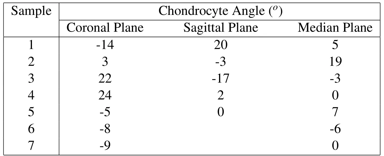
Table 4:FFT analysis of the chondrocyte’s orientations in the coronal,sagittal and median planes of endplate specimens.
Other studies using clinical methods performing specimens anatomical sectioning at the millimeter scale by MRI scans[Kakitsubata,Theodorou,Theodorou,Trudell,Clopton,and Resnick(2002)]or histological slicing[Wang,Videman,and Battie(2012)]have shown the importance of the endplate in the verterbral disc degeneration in two key mechanisms namely endplate perforation into the subchondral bone and herniation into the IVD.These pathologies create a loss in hydrostatic pressure in the NP and negative disruption to the nutritional capillary pathways below the endplate to the IVD[Holm,Holm,and Ekstrom(2004)]by solute diffusion from the blood supply in the vertebral body[Roberts,Menage,and Urban(1989)]similar to the one observed in articular cartilage[Roberts,Urban,Evans,and Eisenstein(1996)].Finer visualisations of the endplate structure is therefore crucial to assess a pathology advancement in the cartilaginous endplate in the presence of facet joint osteoarthritis using for instance MRI [Fujiwara, Lim, An, Tanaka, Jeon, Andersson,and Haughton(2000)]and in the osseous endpolate by determining local thickness and BMD using micro-CT[Wang,Jiang,Deng,Wang,Fu,and Zhang(2011)].Additionally,vascular channels and ossification gaps have been observed[Coventry,Ghormley,and Kernohan(1945)]after 19 and changes in Type X collagen present in fetal and adult endplates[Aigner,Greskotter,Fairbank,von der Mark,and Urban(1998)]has been shown to bind calcium linked to local calcification leading to progressive disc degeneration.The distribution of the different types of collagen fibers such as Type I, II and X can be also visualised in the IVD, endplate and the vertebral bone by special immuno-staining tests[Nosikova,Santerre,M.Grynpas,G.Gibson,and Kandel(2012);Rufai,M.Benjamin,and Ralphs(1995);Hayes,Hughes,Ralphs,and Caterson(2011)].Collagen staining method and a large number of samples has not been used in the presented preliminary work but is considered for further studies.Because our human samples had been frozen for a long period and had also been chemically treated,preliminary qualitative mechanical tests could be performed here and further studies intend to apply the presented procedure on fresher non treated samples.
A 3D schematic modelling of the fibrillar structure formed in the NP and AF that attaches into the endplate observed in the literature[Wade,Robertson,and Broom(2012)]is illustrated by our observations in the undecalcified samples.In the third decade,retrograde changes are seen such as microcracks or rupture of the endplate and fibrillation of the cartilage[Coventry,Ghormley,and Kernohan(1945)].In older subjects,thinning,irregularities,erosion,cartilaginous defects and Schmorl nodes can be detected by micro MRI[Kakitsubata,Theodorou,Theodorou,Trudell,Clopton,and Resnick(2002)]and have been visualised in our TLM samples and some of our RLM specimens.Previous morphological grading of the endplate damage has been implemented by Grignonet al.,[Grignon,Grignon,and Mainard(1999)]on histology slides following the method of Gunzburget al.,[Gunzburg,Parknison,and Moore(1992)]classifying pathologies based on morphological observations for large numbers of samples,but this procedure was not compatible with our procedure.Previous research by Robertset al.[Roberts,Menage,and Urban(1989)]found that the cartilaginous endplate was composed of hyaline cartilage with an approximate thickness of 600µm.Wanget al.[Wang,Jiang,Deng,Wang,Fu,and Zhang(2011)]showed that the cranial endplate thickness at the cen-tral vertebral region ranges from 580-2000µmand Pitzenet al.[Pitzen,Schmitz,Georg,Barbier,Beuter,Steudel,and Reith(2004)]found that the endplate thickness varied from 720-1350µmat the peripheral region and 650-840µmin the central region.Our average measurements of the cartilaginous endplate thickness of 432.9±89.3µmare consistent with the literature for central region measurements under the NP where fluid nutrition is crucial.
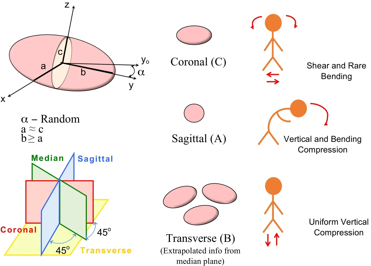
Figure 22:Schematic illustrations showing the cell shapes and orientations in coronal,sagittal planes and extrapolated shapes and orientations in the transverse planes.The suspected loading in the respective planes are also shown.
Efficient observations of the surface of polished specimens of a single vertebral segment were possible under RLM microscopy to visualise the three distinct tissues of the IVD,the cartilaginous endplate and the subchondral bone.Histochemical staining of undecalcified and decalcified slides by using basic fuchsin and toluidine blue and H&E respectively confirmed the presence of densely populated chondrocytes and various micro damages in the endplate in the central vertebral region particularly in elderly patient under TLM microscopy.Both microscopy methods contributed to precisely measure the human endplate thickness and visualise a large diversity of microdamage observed in elderly patients.Qualitative estimations of the endplate stiffness ratio compared to the adjacent bone using nano-indentation[Hoffler,Moore,Kpzloff,Zysset,Brown,and Goldstein(2000)]confirmed the dual soft-er cartilaginous and stiffer osseous nature of the endplate.FFT image analysis of decalcified endplate samples revealed chondrocytes of usually flattened shapes in the coronal plane[Korhonen,Julkunen,Wilson,and Herzog(2008);Farnum and J.Wilson(2011)]and no specific orientation in the transverse plane confirmed by round-shaped cells in the sagittal and median plane[Rodriguez and Slichter(2009);Roberts,Menage,and Eisenstein(1993);Roberts,Menage,Duance,Wotton,and Ayad(1991);Coventry,Ghormley,and Kernohan(1945)]in response to adominant uniform vertical compression.
Acknowledgement:The authors are grateful for the research support of NSFCMMI-MOM 090498 and NSF-CMMI-BMMB 1214816 and the University of Illinois at Chicago.The authors are also thankful to Dr.Thierry Hoc from LMSSMat Laboratory at Ecole Centrale Paris,Ms Deborah Hall,Ms Erica Dahlmeier and Mr Robert Urban from the Robbins and Jacobs Family Biocompatibility and Implant Pathology Laboratory at the Dept.of Orthopaedic Surgery,Rush University Medical Center,for their collaboration with sample preparation and microscopy.Human cadaver tissues were manipulated in agreement with Rush University policy.
Aigner,T.;Greskotter,K.;Fairbank,J.;von der Mark,K.;Urban,J.(1998):Variation with age in the pattern of type x collagen expression in normal and scoliotic human intervertebral discs.Calcified Tissue International,vol.63,pp.263–268.
Antoniou,J.;Steffen,T.;Nelson,F.;Winterbottom,N.;Hollander,A.P.;Poole,R.A.;Aebi,M.;Alini,M.(1996): The human lumbar intervertebral disc:Evidence for changes in the biosythesis and denaturation of the extracellular matrix with growth,matiration,ageing and degeneration.Journal of Clinical Investigation,vol.98,no.4,pp.996–1003.
Aufdermaur,M.;Fehr,K.;Lesker,P.(1980): Quantitative histochemical changes in intervertebral disc in diabetes.Exp Cell Biol,vol.48,pp.89–94.
Battie,M.;Videman,T.;Gibbons,L.(1995): Detriments of lumbar disc degeneration.a study relating lifetrime exposures and magnetic resonance imaging findings in identical twins.Spine,vol.20,pp.2601–2612.
Bernick,S.;Caillet,R.(1982):Vertebral endplate changes with aging of human vertebrae.Spine,vol.7,pp.97–102.
Bibby,S.;Fairbank,J.;Urban,M.(2002):Cell viability in scoliolitic discs in relation to disc deformity and nutrient levels.Spine,vol.27,pp.2220–2227.
Biering-Sorenson,F.(1982):Low back trouble in general population of 30-,40-,50-,and 60-,year old men and women.study design representativeness and basic results.Dan Med Bull,vol.29,pp.289–99.
Brodin,H.(1955):Paths of nutrition in articular cartilage and intervertebral discs.Acta Orthop Scand,vol.24,pp.177–183.
Chao,E.;Inoue,N.;Elias,J.;Frassica,F.(2000): Image-based computational biomechanics of the musculoskeletal system.Handbook of Medical Imaging,Processing and Analysis.San Diego:Academic,vol.1,pp.285Ð298.
Compston,J.E.;Vedi,S.;Webb,A.(1985): Relationship between toluidine blue-stained calcification fronts and tetracycline-labeled surfaces in normal human illiac crest biopsies.Calcified Tissue International.,vol.37,no.4,pp.32–35.
Coventry,M.;Ghormley,R.;Kernohan,J.(1945):The intervertebral disc its microscopic anatomy and pathology.J Bone Joint Surg,vol.27,pp.233–247.
Dudli,S.;Haschtmann,D.;Ferguson,S.J.(2012): Fracture of the vertebral endplates,but no equienergetic impact load,promotes disc degeneration in vitro.Orthopaedic Research Society.,,no.8,pp.809–817.
Farnum,C.E.;J.Wilson,N.(2011): Orientation of primary cilia of articular chondrocytes in three-dimensional space.Anatomical Record-Advances in Integrative Anatomy and Evolutionary Biology,vol.294,no.3,pp.533–549.
Fields,A.;Sahli,F.;Rodriguez,A.;Ramos,J.;Keaveny,T.;Lotz,J.(2012):Comparison of biomechanical behavior,morphology,and disc health between double-layer and single-layer endplates.ORS Annual Meeting.
Fujiwara,A.;An,H.S.;Lim,T.-H.;Haughton,V.M.(2001): Morphological changes in the lumbar intervertebral foramen due to flexion-extension,lateral bending,and axial rotation.Spine,vol.26,no.28,pp.876–882.
Fujiwara,A.;Lim,T.-H.;An,H.S.;Tanaka,N.;Jeon,C.-H.;Andersson,G.B.J.;Haughton,V.M.(2000):The effects of disc degeneration and facet joint osteoarthritis on the segmental flexibility of the lumbar spine.Spine,vol.25,no.23,pp.3036–3044.
Grignon,B.;Grignon,Y.;Mainard,D.(1999):The structure of the cartilaginous endplates in elder people.Surg Radiol Anat,vol.22,pp.13–19.
Gruber,H.;Ashraf,N.;Norton,H.(2003):Vertebral endplate architecture and vascularization:Application of micro-computerized tomography,a vascular tracer and immunocytochemistry in analyses of disc degenration in aging sand rat.Spine,vol.30,no.23,pp.2593–2600.
Gruber,H.;Hanley,E.(1998):Analysis of aging and degradation of the human intervertebral disc.comparison of surgical specimens.Spine,vol.23,pp.751–757.
Guerin,H.;Elliott,D.(2006): Degeneration affects the fiber reorientation of human annulus fibrosus under tensile load.J Biomechanics,vol.39,pp.1410–1418.
Gunzburg,R.;Parknison,R.;Moore,R.(1992):A cadaveric study comparing discography,magnetic resonance imaging,histology and mechanical behaviour of human lumbar disc.Spine,vol.17,pp.417–426.
Hansson,T.;Holm,S.(1991): Clinical implications of vibrations-induced changes in the lumbar spine.Orthop clin North Am,vol.22,pp.247–253.
Hayes,A.J.;Hughes,C.E.;Ralphs,J.R.;Caterson,B.(2011):Chondroitin sulphate sulphation motif expression in the ontogeny of the intevertebral disc.European Cells and Materials.,vol.21,no.15,pp.1–14.
Hoc,T.;Henry,L.;Verdier,M.;Aubry,D.;Sedel,L.;Meunier,A.(2006):Effect of microstructure on the mechanical properties of haversian cortical bone.Bone,vol.38,pp.466–474.
Hoffler,C.;Moore,K.;Kpzloff,K.;Zysset,P.;Brown,M.;Goldstein,S.(2000): Heterogeneity of bone lamellar-level elastic moduli.Bone,vol.26,pp.603–609.
Holm,S.;Holm,A.;Ekstrom,L.(2004):Experimental disc degenration due to endplate injury.J Spinal Disord Tech,vol.17,no.1,pp.64–71.
Horner,H.;Urban,J.(2001):Effect of nutrient supply on the viability of cells from the nucleus pulposus of the intervertebral disc.Spine,vol.26,pp.2543–2549.Hulme,P.A.;Boyd,S.K.;Ferguson,S.J.(2007):Regional variation in vertebral bone morphology and its contribution to vertebral fracture strength.Bone,vol.41,no.12,pp.946–957.
Inoue,N.;Espinoza.Orías,A.A.(2011): Biomechanics of intervertebral disk degeneration.Orthopedic Clinics of North America.,vol.42,no.4,pp.487–499.
Inoue,N.;Sakakida,K.;Yamashita,F.;Hirai,T.;Katayama,T.(1987):The elastic modulus of cancellous bone:Dependence on trabecular orientation.Biomechanics:Basic and Applied Research,vol.1,pp.207Ð212.
Jones,K.;Inoue,N.;Tis,J.;McCarthy,E.;McHale,K.;Chao,E.(2005):Quantification of the microstructural anisotropy of distraction osteogenesis in the rabbit tibia.Iowa Orthop J.,vol.25,pp.118Ð122.
Kakitsubata,Y.;Theodorou,D.J.;Theodorou,S.J.;Trudell,D.;Clopton,P.L.;Resnick,D.(2002):Cartilaginous endplates of the spine: Mri with anatomic correlation in cadavers.Journal of Computer Assisted Tomography.,vol.26,no.6,pp.933–940.
Karupilla,L.;Pentilla,A.;Karhunen,P.(1994):Lumbar disc degeneration and artherosclerosis of the abdominal aorta.Spine,vol.19,pp.923–929.
Kauppila,L.(1997): Prevelance of stenotic changes in arteries supplying the lumbar spine:a postmortem angeographic study on 140 subjects.Ann Rheum Disc,vol.56,pp.591–595.
Konttinen,J.;Pyka,P.;Kangas,M.(2007): Fourier transform in image processing.University of Technology of Lappeenrenta computer science lectures,vol.1.
Korhonen,R.K.;Julkunen,P.;Wilson,W.;Herzog,W.(2008):Importance of collagen orientation and depth-dependent fixed charge densities of cartilage on mechanical behavior of chondrocytes.Journal of Biomechanical Engineering,vol.130,pp.021003–1–021003–11.
Kurunlahti,M.;Tervonen,O.;Vanharanta,H.;Ilkko,E.;Suramo,I.(1999):Association of arthoscelorsis with low back pain and degree of disc degeneration.Spine,vol.24,pp.2080–2084.
Lawson,L.;Brabant,J.(2007):Adobe Photoshop 7.2 tutorial.University of Arizona.
Moore,R.J.(2000):The vertebral end-plate:what do we know?Spine,vol.9,no.5,pp.92–96.
Mwale,F.;Roughley,P.;Antoniou,J.(2004): Distinction between the extracellular matrix of the nucleus pulposus and hyaline cartilage:A requisite for tissue engineering of intervertebral disc.European Cells and Materials.,vol.8,no.7,pp.58–64.
Nachemson,A.;Lewin,T.;Maroudas,A.;Freeman,M.(1970): In vitro diffusion of dye through the end-plates and the annulus fibrosus of human lumbar inter-verebral discs.Acta Orthopaedica,vol.41,no.6,pp.589–607.
Natarajan,R.;Ke,J.;Andersson,G.(1994):A model to study the disc degeneration process.Spine,vol.19,pp.259–265.
Noshchenko,A.;Plaseied,A.;Patel,V.V.;Burger,E.;Baldini,T.;Yun,L.(2012):Correlation of vertebral strength topography with 3-dimensional computed tomography structure.Spine,,no.24.
Nosikova,Y.S.;Santerre,J.P.;M.Grynpas;G.Gibson;Kandel,R.A.(2012):Characterization of the annulus fibrosus-vertebral body interface:identification of new structural features.Journal of Anatomy,,no.13.
Oda,J.;Tanaka,H.;Tsuzuki,N.(1983): Inter vertebral disc changes with aging of human cervical vertebrae from the neonate to the 80’s.Spine,vol.13,pp.1205–1211.
Oliver,W.;Pharr,G.(1992):An improved technique for determining hardness and elastic modulus using load and displacement sensing indentation experiments.J.Mater.Res.,vol.7,no.6,pp.1563–1583.
Pattappa,G.;Li,Z.;Peroglio,M.;Wismer,N.;Alini,M.;Grad,S.(2012):Diversity of intervertebraldisc cells:phenotypeand function.Journal of Anatomy.,vol.221,no.17,pp.480–496.
Pitzen,T.;Schmitz,B.;Georg,T.;Barbier,D.;Beuter,T.;Steudel,W.I.;Reith,W.(2004):Variation of endplate thickness in the cervical spine.Spine,vol.13,no.6,pp.235–240.
Reinking,L.(2007):ImageJ Basics v1.38.Millersville University.
Resnick,D.;Niwayama,G.(1978): Intervertebral disc abnormalities associated with vertebral metastasis:Observations in patients and cadavers with prostatic cancer.Investigative radiology.,vol.13,no.9,pp.182–190.
Roberts,S.;Menage,J.;Duance,V.;Wotton,S.;Ayad,S.(1991): Collagen types around the cells of the intervertebral disc and cartilage endplate:an immunohistochemical study.Spine,vol.16,pp.1030–1038.
Roberts,S.;Menage,J.;Eisenstein,S.(1993): The cartilage endplate and intervertebral disc in scoliosis-calcification and other sequelae.J Orthop Res,vol.11,pp.747–757.
Roberts,S.;Menage,J.;Urban,J.(1989):Biochemical and structural properties of the cartilage end-plate and its relation to the intervertebral disc.Spine,vol.14,pp.166–174.
Roberts,S.;Urban,J.;Evans,H.;Eisenstein,S.(1996):Transport properties of the human cartilage end-plate in relation to its composition and calcification.Spine,vol.21,pp.415–420.
Rodriguez,A.;Slichter,C.(2009): Human disc nucleus properties relate to endplate permeability.Abstract in ISSLS.
Rodriguez,A.G.;Rodriguez-Soto,A.E.;Burghardt,A.J.;Berven,S.;Majumdar,S.;Lotz,J.C.(2012):Morphology of human vertebral endplate.Journal of Orthopaedic Research,,no.8.
Rodriguez,A.G.;Slichter,C.K.;Acosta,F.L.;Rodriguez-Soto,A.E.;Burghardt,A.J.;Majumdar,S.;Lotz,J.C.(2011): Human disc nucleus properties and vertebral endplate permeability.Spine,vol.36,no.7,pp.512–520.
Rufai,A.;M.Benjamin;Ralphs,J.(1995):The development of fibrocartilage in the rat intervertebral disc.Anat Embryol.,vol.192,no.10,pp.53–62.
Sambrook,P.;MacGregor,A.;Spector,T.(1994):Genetic influences on cervical and lumbar disc degeneration:a magnetic resonance imaging study in twins.Arthritis Rheum,vol.42,pp.366–372.
Schmorl,G.;Junghanns,H.(1971):The human spine in health and disease.Hibbit,Karlsson&Sorensen,New York.
Singha,K.;Singha,M.(2012): Biomechanism profile of intervertebral disc’s(ivd):stratergies to successful tissue engineering for spinal healing by reinforced composite structure.Journal of Tissue Science and Engineering,vol.3,no.13.
Taylor,J.;Twomey,L.(1993):The development of human intervetebral disc.CRC Press,Boca Raton.
Urban,J.;Smith,S.;Fairbank,J.(2004): Nutrition of the intervertebral disc.Spine,vol.29,pp.2700–9.
Videman,T.;Nurminen,M.;Troup,J.(1990): Lumbar spinal pathology in cadaveric material in relation the history of back pain,occupation and physical loading.Spine,vol.15,pp.728–740.
Wade,K.R.;Robertson,P.A.;Broom,N.D.(2012):On how nucleus-endplate integration is achieved at the fibrillar level in the ovine lumbar disc.Journal of Anatomy.,vol.221,no.7,pp.39–46.
Wang,F.;Jiang,J.-M.;Deng,C.-H.;Wang,F.-L.;Fu,Z.-Z.;Zhang,Z.-F.(2011): Expression of fas receptor and apoptosis in vertebral endplates with degenerative disc diseases categorised as modic type i or ii.Injury.,vol.42,no.6,pp.790–795.
Wang,Y.;Battie,M.C.;Boyd,S.K.;Videman,T.(2011):The osseous endplates in lumbar vertebrae:Thickness,bone mineral density and their associations with age and disk degeneration.Bone,vol.48,no.6,pp.804–809.
Wang,Y.;Videman,T.;Battie,M.C.(2012):Lumbar vertebral endplate lesions.Spine.,,no.8,pp.1432–1439.
Wilder,D.;Pope,M.(1996): Epidemiological and aetiological aspects of low back pain in vibration environments-an update.Clin.Biomech.(Bristol,Avon),vol.11,pp.61–73.
World,I.(2007):I.h.c.team.IHC World-Life Science Information Network.
 Computer Modeling In Engineering&Sciences2014年9期
- Computer Modeling In Engineering&Sciences的其它文章
- Variable Viscosity and Density Biofilm Simulations using an Immersed Boundary Method,Part I:Numerical Scheme and Convergence Results
- Activation Pattern of Nuclear Factor-kB in Skin after Mechanical Stretch–a Multiscale Modeling Approach
- A Computational Modeling Framework for Heat Transfer Processes in Laser-Induced Dermal Tissue Removal
- Molecular Dynamics Simulations of Ions Diffusion in Carbon Nanotubes Embedded in Cell Membrane
