
Intelligent Temperature Control System Design Based on Single-Chip Microcomputer
2014-03-14 06:45:56JunLiXianLinMengWenLongSong
Jun Li,Xian-Lin Meng,Wen-Long Song
(1.College of Mechanical and Electrical Engineering,Northeast Forestry University,Harbin 150040,China; 2.School of Municipal and Environmental Engineering,Harbin Institute of Technology,Harbin 150001,China)
1 Introduction
Temperature is the representation of a physical quantity of hot and cold objects and one of the most basic physical quantity in our production and life.Temperature measurement is related to various fields of industry and agriculturalproduction. Temperature control is of critical importance to ensure the effectiveness of the industrial production.Temperature control system also is an important part of vacuum smelting process[1].Therefore,the temperature control system is widely used such as industrialized culture[2],green granary[3], Fumigation therapy[4], airconditioning system[5],and so on.How to select an approximately optimal control strategy through real-time monitoring data becomes a key factor for the energysaving operation[6-7].
Various strategieshave been applied on the temperature controlsystem.The fuzzy self-tuning proportional-integral-derivative (PID) algorithm,which is easy to implement and be effective,has been widely used in the temperature control system[8].An optimal approach temperature(OAT)control strategy is proposed for resetting the condensing water temperature hourly,so to maximize the performance of the combined water chiller and cooling tower system[9].Zhen proposed a typical multi-variable,large time delay and nonlinear system,self-extracting rules fuzzy control(SERFC)method to maintain a stable temperature value in a built environment chamber with supply air system and hot-water system[10].Based on the modified output-input feedback(OIF)Elman neuralnetworksand the prediction principle,an adaptive PID decoupling controller is designed to achieve the rapid,precise and especially independent control for the upstream and downstream temperatures of the double-level air flow field dynamic vacuum (DAFDV)coupling system[11].
The present study focuses on software designs including approaches and strategies to control temperature changes in different application fields and the research work oftemperature controlsystem hardware design are relatively small amount.However,if there is no corresponding hardware support,a good method is also unable to be used.In this paper,the main work is to design for the hardware circuit.We use single chip microcomputer to develop intelligent temperature controlsystem,which has a higher controlconvenient,low cost,flexibility advantages.Itis proved in the experiment that the design has the obvious effect for technical indicators to improve the temperature control.As the hardware support,our control system will be fit for other temperature control methods.
2 System Structure Design
The control system includes four units,such as monitor,heater,controlled process(storage tank)and feedback loop(temperature detection circuit).Fig.1 shows the diagram of the designed control system.
In Fig.1,the water tank is the controlled object; the temperature of the water tank is detected by the temperature sensor and then the signal is transmitted to the single chip microcomputer.The feedback signal and the prefabricated signal are compared with SCM which will give the quantity of temperature control.The heater will receive heating instructions.Finally,the power controller can control the heating power of the heating pipe and the temperature will be controlled in our system.Here,the interference signal is mainly due to the heating power changes caused by contact with other objects.
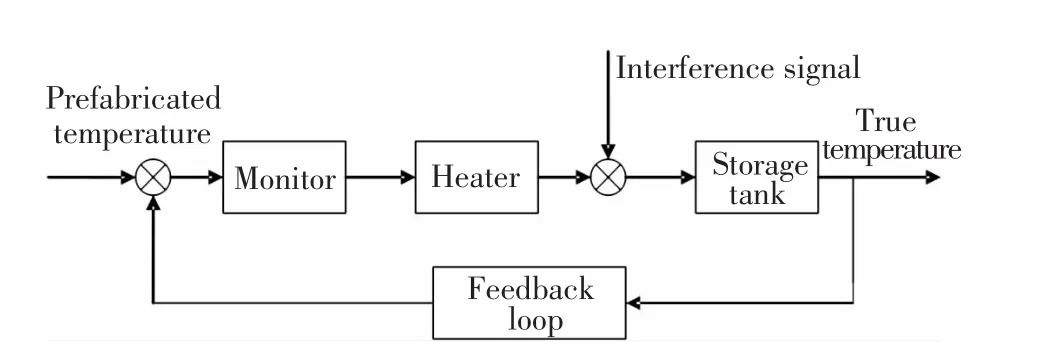
Fig.1 The system structure diagram
3 System Circuit Design
According to the structure diagram of control system,we can build the circuit principle diagram,as shown in Fig.2.

Fig.2 System circuit diagram
In this paper,it is assumed that the controlled object is a closed tank.The system is composed of a temperature detection circuit,a power control circuit,a water level detection circuit,a keyboard and display circuit,alarming circuit and SCM ATP89C52[12].
3.1 Temperature Detection Circuit
In this part,we use digital temperature sensor DS18B20[13]to detect temperature.Fig.3 shows the package diagram of DS18B20.A new generation of“bus line”DS18B20 is designed by Dallas company for the production of digital temperature sensor.It is suitable for various harsh environments and it has many advantages,such as convenient connection,simple temperature measurement circuit,small size,low price and strong anti-interference ability.
3.2 Power Control Circuit
Here we adopt optical coupler MOC3041[14]to implement the power control circuit,which is coupled transmission signal,and isolating the effects of interference.Fig.4 shows the power control circuit.The heat port provides an output signal of heating drive;through the 74LS04 inverter,the reverse signal will drive optical coupler MOC3041.When the heat outputs high level,the RP is low and the circuit is in ON-state,that is,both bidirectional thyristor and the heat circuit get through,and then the water tank is heated by power pipes.
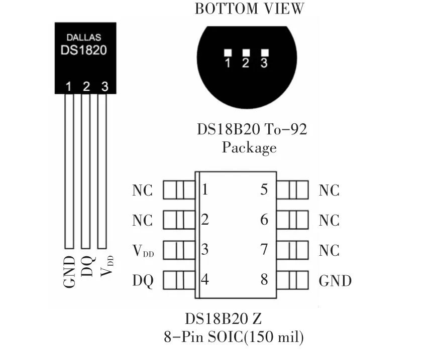
Fig.3 Package diagram of DS18B20
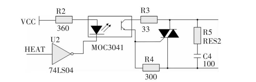
Fig.4 Power control circuit
3.3 Water Level Detection Circuit
For costsaving,we design the waterlevel detection circuit by means of conductivity of water.As shown in Fig.5,three metal bars are respectively installed at different height of the water tank.The bar A is at the bottom of the water tank and connected with a power supply of 5 V;the bar B and C represent the lowest and highest level,which ground through a resistance.When the water level is below B,B and C are all higher than the water surface,and then no electricity,the status of b and c is"0".At the same time,the system gives the alarm signal,and the indicator light of less water works, and the electromagnetic water valve is turned on to inject water;when the water level rises to B,A and B are connected;the status of b is"1"and c is"0".The alarm signal disappears and the indicator light of normal works.When the water level rises to C,C and B are connected,and the status of b and c is"1",then the valve is closed and stop injection.
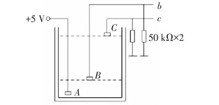
Fig.5 Water level detection principle diagram
3.4 Keyboard and Display Circuit
Keyboard with four keys is directly connected with the microcontroller P1 port as prefabricated temperature input port setting in Fig.6(a).We choose LCD1602[15](16×2 character dot matrix LCD screen) as liquid crystal display circuit,which can achieve human-computer interaction,such as prefabricated temperature and real time detection of temperature as shown in Fig.6(b).
3.5 Alarming Circuit
A buzzer and a light emitting diode consist of the alarming circuit,as shown in Fig.7.When the water level of the tank is lower than the floor,the buzzer gives out the alarm and the system turns on the light of less water;otherwise when the water level of the tank reaches the upper threshold,the system turns off the light of less water and turns on the light of normal water level.
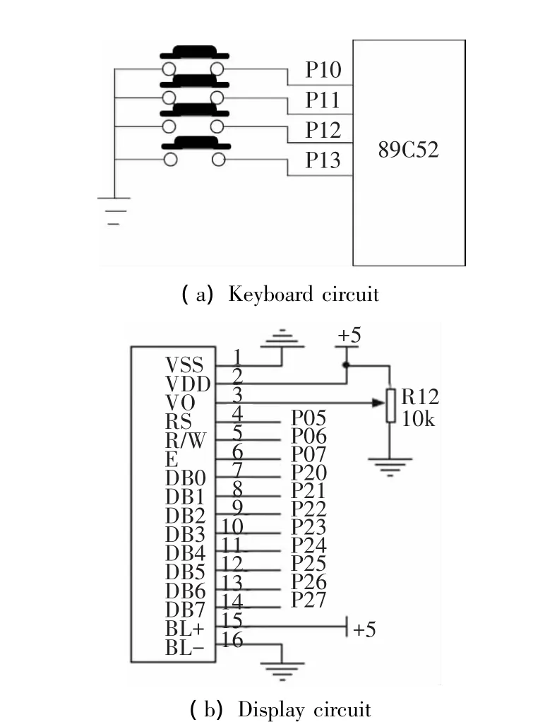
Fig.6 Keyboard and display circuit
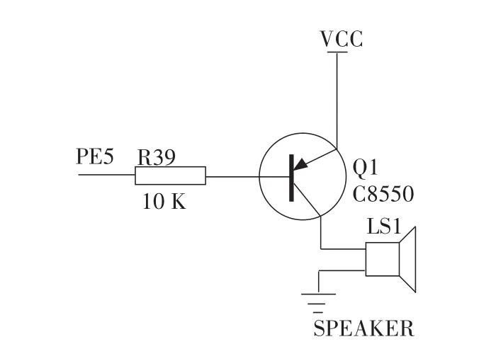
Fig.7 The alarming circuit
4 Test Results
4.1 System Testing Instrument
There are many instruments used in our test,such as dual tracking voltage and current stabilized power supply(DH1718E-5),digital oscilloscope(Tektronix TDS1002),emulators(WEIFUE6000/L),Multifunctiondigitalmeter(GDM-8145), PC (P4 CPU2.4),a thermometer,electric heating cups and a stopwatch.
4.2 Test Results
1)We put 1 litre water into the thermostat electrothermal cup and change its temperature.We can observe the temperature value on liquid crystal display (LCD1602),while we measure the real temperature with a thermometer and record the results,as shown in Fig.8.
We can conclude that the static temperature sensor measurement results and actual measurement of the thermometer is consistent.Therefore,the results of measurement with temperature sensor are reliable and the system can comply with the design requirement.
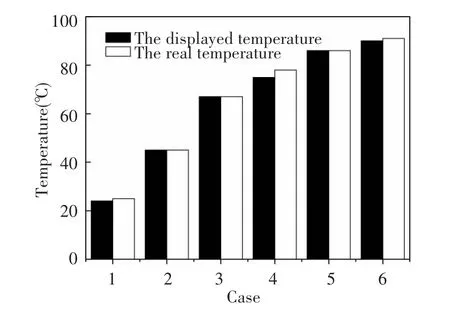
Fig.8 The static temperature results
2)The target temperature is set 75℃.We can observe the temperature value on liquid crystal display (LCD1602),while we measure the water temperature with the thermometer every 30 seconds and record the results,as shown in Fig.9(before heating,the temperature is 25℃).
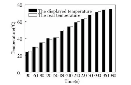
Fig.9 The dynamic temperature results
By comparison,we can see that the measured temperature and the real temperature consistent in the process of heating and errors are in the permitted range.Although there are errors,they can not affect the results.Therefore oursystem reachesdesign requirements.
5 Conclusions
This paper focuses on the application of single chip microcomputer in temperature control.We use single chip microcomputer AT89C52 as the control core and design the intelligent control system with the temperature real-time acquisition and control.The test results show that our design is reasonable and achieves the desired effect.The system realizes the intelligent temperature control,at the same time it has many advantages,such as easy to control,low cost and high flexibility.
[1]Wei J G,Jiang X C.Design of an intelligent temperature control system based on the fuzzy self-tuning PID.Procedia Engineering,2012,43:307-311.
[2]Xu J Q,Wang X Z,Yu G Y.Industrialized culture water temperature control system design and simulation.Automation&Instrumentation,2013,1:66-68.
[3] Shi Q S.Green granary temperature control system modeling and simulation.Physics Procedia,2010,25: 2263-2267.
[4]Zhang H F,Zhao A L,Hou J.Design of fumigation temperature control system based on single-chip microcontroller.Physics Procedia,2011,11:246-250.
[5]Zhang X J,Yu C Y,Li S,et al.A museum storeroom airconditioning system employing the temperature and humidity independent control device in the cooling coil.Applied Thermal Engineering,2011,31(17-18):3653-3657.
[6]Yu F W,Chan K T.Improved energy performance of air cooled centrifugal chillers with variable chilled water flow.Energy Conversion and Management,2008,49:1595-1611.
[7]Mahenjun Z J,Wang S W,Xiao F.Online performance evaluation of alternative control strategies for building cooling water systems prior to in situ implementation.Applied Energy,2009,86:712-721.
[8]Pen Y Q.Application of hybrid fuzzy PID in Gelaton temperature control system based on PLC.Journal of Xiamen University,2008,47(2):191-195.
[9]Liu C W,Chua Y K.A study on an optimal approach temperature control strategy of condensing water temperature for energy saving.International Journal of Refrigeration,2011,34:816-823.
[10]Zhen L,Zhang J L,Chen Y P,et al.Fuzzy control model and simulation of supply air system in a test rig of lowtemperature hot-water radiator system. Energy and Buildings,2010,42:386-392.
[11]Li J Y,Feng M X.Temperature decoupling control of double-level air flow field dynamic vacuum system based on neuralnetwork and prediction principle.Engineering Applications of Artificial Intelligence,2013,26:1237-1245.
[12]Feng Y.Design of temperature control system based on AT89C52.Journal of Weinan Teachers University,2011,26(2):49-52.
[13]Zhang J.Smart temperature sensor DS18B20 and its application.Instrumentation Technology,2010,4:68-70.
[14]Yu Chunhe,Zhang Danping.An artificial intelligence central air-conditioning controller.Advances in Intelligent Systems,2012,138:19-25.
[15]Sui Q J.Interface design and simulation of LCD1602 based on PROTEUS.Microcomputer Information,2010,26(7-1):171-172.
 Journal of Harbin Institute of Technology(New Series)2014年3期
- Journal of Harbin Institute of Technology(New Series)的其它文章
- Aerodynamic Characteristics of Projectile with Exotic Wraparound Wings Configuration
- Numerical Simulation of High-Speed Water Entry of Cone-Cylinder
- Influence of Punch Shape on the Fracture Surface Quality of Hydropiercing Holes
- Synchronization of High-order Discrete-time Linear Complex Networks with Time-varying Delays
- Simulation Platform of Underwater Quadruped Walking Robot Based on MotionGenesis Kane 5.3 and Central Pattern Generator
- Backstepping Adaptive Controller of Electro-Hydraulic Servo System of Continuous Rotary Motor