Aerodynamic Characteristics of Projectile with Exotic Wraparound Wings Configuration
Fu Zhang,Wen-Jun Ruan,Hao Wang,Chen-Guang Zhu,Meng-Hua Zhang
(School of Energy and Power Engineering,Nanjing University of Science and Technology,Nanjing 210094,China)
1 Introduction
Since the advent of wraparound wings(WAW)in the mid-1950s,they have been widely used in various tactical and strategic weapons,such as long-range rocket,antitank missile,terminal-guided projectile,aerial bomb,and cruise missile.Adopting a tube launch can effectively reduce the space requirements and improve the initial accuracy of these weapons.The weapons packaged in a launch canister may not only improve the reliability of the weapon system but also facilitate weapon transportation and storage. The tacticalweaponswith WAW orwraparound fins (WAF)consist of five different configuration types,namely,wing-tail,tailless,conventional,canard,and exotic configuration which unconventionally meet the special needsoftacticalweapons[1-2].WAF and WAW,which have broad prospects for application and unique aerodynamic properties,have attracted much attention from scientific research personnel and professional and technical staff.However,the studies on the subsonic and transonic flight of projectiles with exotic WAW configuration are rare in the literatures.By the use of explicit coupling method and Spalart-Allmaras turbulence model,it showed the formation cause of the side force,through the pressure analysis of WAF[3].The unsteady flow field of the WAF rocket was numerically simulated and analyzed the cause of the formation of the rolling moment of the WAF rocket[4].By using advection upwind splitting method (AUSM),it analyzed the changes in the aerodynamic coefficients of WAF-body combinations with varying Mach numbers and attack angles[5].CFD and the semi-empirical method were utilized to compare the aerodynamic characteristics of the folding multisurface of the diamond back wing with the same airfoil,chord,and surface area[6].By adoption of proper algebraic grid generation,the glide bullet and the two sets of empennage bullet were calculated and studied in Refs.[7]and[8],respectively.
This study fully utilizes the characteristics of the structured grid and takes advantage of the features of the unstructured grid for the discretization of geometrically complex domains.The Roe scheme is employed to resolve the convective terms,and MUSCL reconstruction is applied to achieve third-order accuracy.The shear-stress transport(SST)k-ω twoequation turbulence model is adopted in this simulation.Time advancement is accomplished by using the lower-upper symmetric Gauss-Seidel method.
Fig.1 shows the structures of projectiles studied in this paper.The head of the projectile consists of three sections:ogive nose,straight,and cone.The projectile body consists of cylindrical sections,and the rear of the projectile is made up of tail rod and six flip-out tail fins.Fig.1(b)shows a configuration with increasing lift and decreasing rolling moment.The installation position of the WAW,which can make good use of space,is behind that of the centroid.A backwardfacing step exists between the WAW and the tail.The maximum projectilediameteris 80 mm and the projectile length is 320 mm.The WAW has a wingspan of 78.5 mm,chord length of 14.5 mm,curvature radius of 36 mm,and opening angle of 45°.Using the WAW may generate aerodynamic interferenceand projectile body in high attack angle,thus making the application of engineering algorithm for computation and correction difficult.Therefore,it is necessary to study the aerodynamic characteristics of the projectile with WAW by using CFD.

Fig.1 Structure of two types of projectiles
2 Grid-Generation Method
Reasonable design and high-quality grid generation are the presupposition of numerical calculation and are also the crucial factors affecting CFD results.Structured and unstructured grids possess their respective merits and drawbacks,and each of them can hardly fulfill the expectations of the increase of CFD development.
This study fully utilizes the characteristics of the structured grid(e.g.,high precision,high efficiency,and high reliability)and takes advantage of the features ofthe unstructured grid (e.g.,easy generation and inherent flexibility) for the discretization of geometrically complex domains.The topology structure of the mesh is shown in Fig.2.
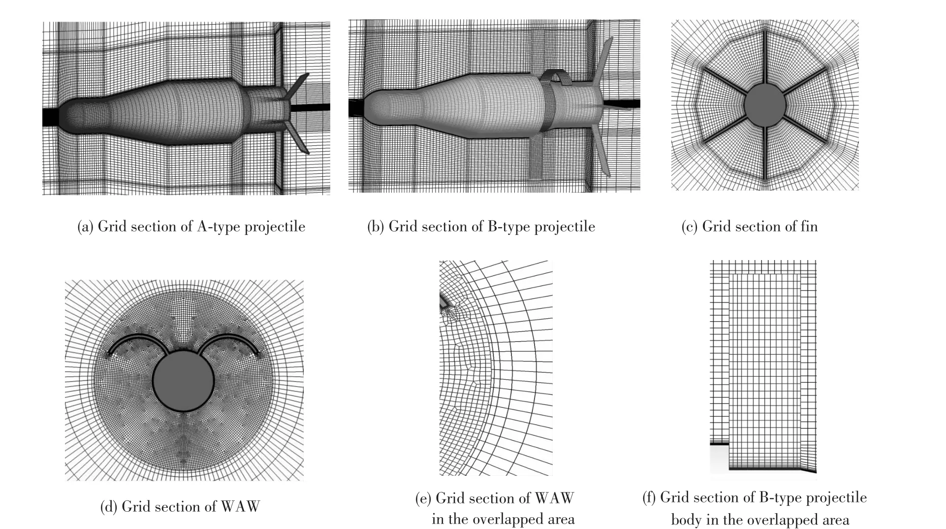
Fig.2 Topology structure of grid
O-type structured grids are designed to surround the projectile body and the tail fin to improve the quality of grids and to refine the boundary layer around the geometry.The approach for generating unstructured grids can be divided into two steps.In the first step,the quadrilateral elements are generated for the WAW cross section.In the second step,hexahedral elements are created by extending these quadrangles along the projectile body axis.The flow-field parameters are transferred by searching and interpolating between structured grids and unstructured grids in the overlapped areas[9-10].The abovementioned methods effectively solve the problem caused by large deformation of grids between WAW and tail fins[11].In order to ensure that the wall y plus is not more than 1.0,the distance of the first-layer grid to the wall is set as 2×10⁻⁶.The growth rate of the boundary-layer thickness is 1.15.The grid quality is efficiently improved by finely adjusting the topology structure and grid distribution.After the test,the total number of grids is about 3 million,and the local minimum angle is 25°.
3 Numerical Method
3.1 Governing Equation
The cell-centered finite-volume method is used to solve3D compressible Reynolds-averaged Navier-Stokes equations.The flow governing equations can be expressed in 3D Cartesian coordinates(x1,x2,x3) as[11-12]
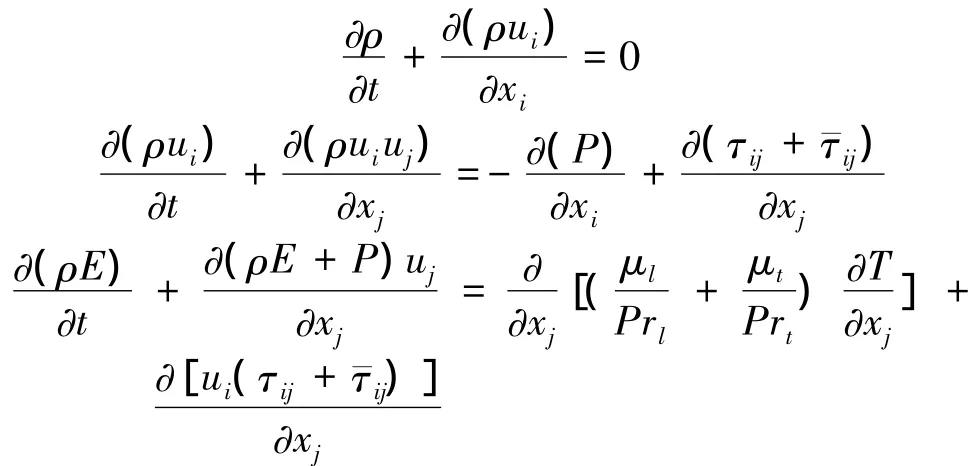
The Roe scheme is employed to resolve the convective terms,and MUSCL reconstruction is applied to achieve third-orderaccuracy. Fora MUSCL scheme,the left and right states of the conservative variables at the cell faces are computed as
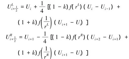
where U is the vector of cell averaged conserved variables;k is a free parameter,which is set to 1/3 for the third-order limiter,and the cells are labeled by the integer i.Additionally,

In this study,the following third-order MUSCL-type limiter is considered:

where M3 is constrained in the normal fashion to firstorder accuracy at local maxima and minima and also includes a“steepening”parameter N to improve the resolution of discontinuities;in this paper,N=2.
The viscous terms are discretized by using the second-order center difference scheme.The shearstress transport(SST)k-ω two-equation turbulence model is adopted in numerical computations.Time advancement is accomplished by using the lower-upper symmetric Gauss-Seidel method.
3.2 Shear Stress Transport Turbulence Model
In this section,the complete formulation of the SST model is given,with the limited number of modifications highlighted[10].F1is equal to zero when away from the surface(k-ε model)and switches over to a surface inside the boundary layer(k-ω model)[13].

3.3 Boundary Condition
No-penetration boundary conditions are adopted in the normal direction of the surface,and no-slip boundary conditions are used in the tangential direction.Free-stream conditions are applied in the far field.
3.4 Numerical Evidence
The numericalexample ofthe firststandard projectile in Ref.[14] is given to show the effectiveness of the proposed method.Figs.3(a)and 3(c)show thatthe liftand pitching moment coefficients agree with the experimental data.Fig.3 (b)shows that the change trend of the drag coefficient is consistent with the experimental data and that the maximum relative error is within 7%.Therefore,the proposed method has high accuracy and good reliability.
3.5 Independence of Grid
In this section,the independence of the grid has been verified.It can be seen from Fig.4 that the lift coefficient of the two types of projectiles slightly changes when the grid number is larger than 3 million.

Fig.3 Comparison results between tests and calculations as Ma=0.6

Fig.4 Lift coefficient of two types of projectiles versus the attack angle
4 Calculation Results and Analyses
The Mach numbers that have been calculated in this study are 0.35,0.5,0.65,0.8,and 0.95,and the attack angles are 0°,2°,4°,6°,8°.Fig.5 provides the definition of the projectile rolling angle φ: as the projectile rolling angle φ increases to 45°,the longitudinal symmetrical plane rotates 45° anticlockwise.When the Mach number is 0.65 and the attack angle is 4°,the pressure distribution,the Mach number distribution,and the streamline distribution of the B-type projectile are given in Figs.6(a)-6(c) and Figs.7(a)-7(b).The contrast curves show the differences between the aerodynamic coefficient of the B-type projectile and that of the A-type projectile(see Figs.6-7 and Figs.9-11).
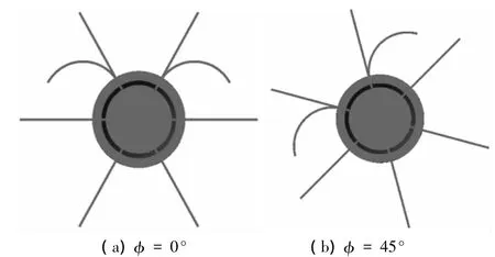
Fig.5 Sketch of different rolling-angle orientations
4.1 Drag Characteristics
Fig.6(a)shows that high pressure exists on the ogive nose and cone section of the B-type projectile and low pressure exists on the joint regions of the ogive nose and straight section,as well as on the joint regions of the cone section and the projectile body,because of the expansion effect of body-surface alteration.Fig.6(b) illustrates that the back flow appears near the trailing edge of the WAW and that the turbulent boundary layer separates on the leeward side of the WAW under strong adverse pressure gradient because of the influence of the attack angle.Fig.6(c)indicates that the distributions of vortex are evidently asymmetrical behind the tail of the B-type projectile when the attack angle is 4°.The lowpressure vortex layers are also formed between the WAW and the tail during the backward-facing step.Under the comprehensive influence of the abovementioned factors,the drag of the B-type projectile increases.Fig.8 shows that the drag coefficient of the two types of projectiles increase when the attack angle increases,which can be described by a parabolic function[15].With the same state parameters,the drag coefficient of the B-type projectile is 13.1%to 18%greater than that of the A-type projectile.Such difference is not significant in the region where the attack angle is near 0°,but significant in the region where the attack angle is close to 8°.This phenomenon is caused by the increase in the windward area and the seriousness of the boundary-layer separation when the attack angle is increased,which significantly increases the pressure drag.The calculation results show that the drag coefficient of the two types of projectiles slightly changes when the rolling angle increases,when the Mach number ranges from 0.35 to 0.95,and when the attack angle is less than 8°.

Fig.6 Contours and streamline distribution of B-type projectile at α=4°,Ma=0.5

Fig.7 Streamline distribution of WAW and fin at α=4°,Ma=0.5

Fig.8 Drag coefficient of two types of projectiles versus the attack angle
4.2 Lift Characteristics
Fig.6(a)shows that the pressure values on the projectile body windward are higher than those on the projectile body leeward.Fig.7 illustrates that the pressure values on the WAW and tail fin windward are higher than those on the WAW and tail fin leeward because of the attack angle with 4°,which produces a stabilizing moment[16].
Fig.9 shows that the lift coefficient of the two types of projectiles decreases with the increase of the Mach number and increases with the increase of the attack angle.This relationship can be described by the linearity rule[15].With the same state parameters,the lift coefficient of the B-type projectile is 21%greater than that of the A-type projectile when the attack angle is 8°.Fig.6(b)shows that flow separation is likely to occur near the leeward side of the WAW at a relatively large attack angle.Therefore,the lift-coefficient curve slope of the B-type projectile slightly decreases when the attack angle is more than 4°.Fig.10 shows that when the free Mach number is 0.5 and the attack angle is 4°,the lift coefficient of the B-type projectile first decreases and then increases, whereas the lift coefficient of the A-type projectile is almost unchanged.When the rolling angle is up to 90°,the lift coefficient of the B-typeprojectilereaches a minimum value because of the decreasing lifting surface area.Under the subsonic condition with the zero attack angle,the pressure of the WAW convex surface is larger than those of the concave surface,which makes the pressure load shift from the convex surface to the concave surface[11,14]. Consequently, the lift coefficient of the B-type projectile at a rolling angle of 180°is larger than that at 0°and the lift coefficient of the B-type projectile at a rolling angle of 135°is larger than that at 45°.

Fig.9 Lift coefficient of two types of projectiles versus the attack angle

Fig.10 Lift coefficient of two types of projectiles versus rolling angle at α=4°,Ma=0.5
4.3 Pitching Moment Characteristics
In this study,the distance between the reference point of the pitching moment and the head of the projectile is 180 mm.Fig.11 shows that the pitching moment coefficient raises toward the negative direction when the attack angle gradually increases.The rising trend of the B-type projectile is significantly greater than that of the A-type projectile because the influence of the WAW increases the lift curve slope.Such difference is not significant in the region where the Mach number is near 0.8,but significant in the region where the Mach number is close to 0.5.Fig.12 shows that the pitching moment coefficient of the A-type projectile is almost constant with the increase of the rolling angle,and the pitching moment coefficient of the B-type projectile slightly changes at the rolling angle ranging from 0°to 90°.When the rolling angle is greater than 90°,the pitching moment coefficient of the B-type projectile slightly raises toward the negative direction because the pressure of the WAW convex surface is larger than that of the concave surface.Therefore,the outstanding advantages of the flight stability of the B-type projectile lie in the region where the Mach number is about 0.5.

Fig.11 Pitching moment coefficient of two types of projectiles versus the attack angle
4.4 Rolling Moment Characteristics
Fig.13 shows that the rolling moment coefficient of the A-type projectile presents periodical variation with the increase of rolling angle.When the A-type projectile is symmetrical on both sides of the vertical plane(rolling angle of 0°,90°,and 180°),the rolling moment coefficient reaches the minimum value.The rolling moment coefficient of the B-type projectile firstly increases and then decreases.It can be seen from Fig.7(a)that the distributions of streamline and pressure are symmetricalon both sides ofthe longitudinal symmetrical plane.So,as the longitudinal symmetrical plane coincides with the vertical plane (rolling angle of 0°and 180°),the rolling moment coefficient of the B-type projectile reaches a minimum value.However,although the longitudinal symmetrical plane is perpendicular to the vertical plane(rolling angle of 90°),the rolling moment coefficient reaches its maximum value.Under the comprehensive influence of the specific laws of stress distribution of the WAW and attack angle,the rolling moment coefficient of the B-type projectile at a rolling angle of 135°is larger than that at 45°,and the rolling moment coefficient of the B-type projectile at a rolling angle of 180°is larger than that at 0°.Although the rolling moment coefficient of the B-type projectile is slightly larger than that of the A-type projectile, the average rolling moment coefficient of the B-type projectile is less than that of the A-type projectile in the entire rollcycle.Therefore, the exotic WAW configuration can effectively reduce the rolling moment in accordance with some specific requirements of the projectile.
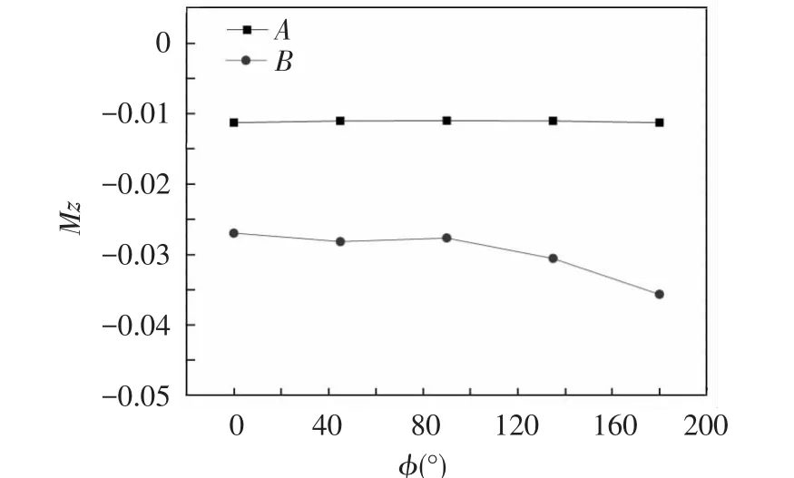
Fig.12 Pitching moment coefficient of two types of projectiles versus rolling angle at α=4°,Ma= 0.5

Fig.13 Rolling moment coefficient of two types of projectiles versus rolling angle at α=4°,Ma=0.5
4.5 Position of the Pressure Center
Fig.14(a)shows that when the Mach number gradually increases,the position of the pressure center of the A-type projectile moves to the directions of the warhead and then to the directions of the tail.This movement is caused by the parts of the high pressure on the head of the A-type projectile holding a dominant position in the pressure center variation when the Mach number varies from 0.35 to 0.65.The high pressure on the windward of the tail and tail fin will take up the dominant status when the Mach number exceeds 0.65.Fig.14(a)shows that with the increase of the Mach number,the position of the pressure center of the B-type projectile slightly changes and moves toward the direction of the tail.It can be seen from Fig.7 that the pressure values on the WAW windward are higher than those on the WAW leeward because of the attack angle with 4°.So,this movement is caused by the influence of the WAW,which makes the windward of the WAW and tail fin occupy the dominant status in the entire range of flight Mach numbers.Therefore,the B-type projectile has better static stability in the flight tests.Fig.14(b)shows that the position of the pressure center of the two types of projectiles slightly changes with the increase of rolling angle.
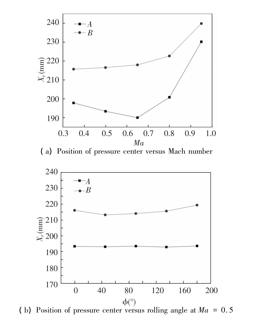
Fig.14 Position of the pressure center of the two types of projectiles at α=4°
4.6 Lift-to-Drag Ratio
Fig.15(a)shows that with the same state parameters,the lift-to-drag ratio ofthe B-type projectile is 9%to 12%greater than that of the A-type projectile.Such difference is not significant in the region where the Mach number is near 1.0,but significant in the region where the Mach number is close to 0.5.Therefore,the WAW of the B-type projectile is more suitable to unfold in the range of the Mach number with 0.5.Fig.15(b)shows that with the increase of the rolling angle,the lift-to-drag ratio of the B-type projectile declines at first and then rises,whereas the lift-to-drag ratio of the A-type projectile is almost unchanged.As the rolling angle increases up to 90°,the lift-to-drag ratio of the B-type projectile reaches its minimum value because of the decreasing lifting surface area.

Fig.15 Lift-to-drag ratio of two types of projectiles at α=4°
5 Conclusions
In this study,two types of fin-stabilized projectiles that have the same body with and without exotic WAW configuration are studied by numerical simulation.On the basis of the analysis and comparison of results,the following conclusion can be drawn:
With the exotic WAW configuration,the drag coefficient of the B-type projectile increases by 18%at most.The lift coefficient of the B-type projectile is about 21%greater than that of the A-type projectile when the attack angle is 8°and the rolling angle is 0°.The difference in the lift-to-drag ratio is not significant in the region where the Mach number is near 1.0,but significant in the region where the Mach number is close to 0.5.With the increase in the rolling angle,the lift-to-drag ratio of the B-type projectile declines at first and then rises.The pitching moment coefficient of the B-type projectile rises toward the negative direction,and the average rolling moment coefficient is significantly less than that of the A-type projectile in the entire roll cycle.As the Mach number increases from 0.35 to 0.95,the position of the pressure center of the B-type projectile shows relatively small changes.
The exotic WAW configuration is simple to design and convenient to install.Therefore,to improve the shooting quality of the fin-stabilized projectile,reduce the rolling moment,and enhance the projectile range,this type of projectile can fully use the tail space to configure the exotic WAW during flight test.Future work will be focused on simulating and researching the aerodynamic characteristics of the exotic WAW configuration with different aspect ratios and opening angles in subsonic,transonic,and supersonic flow.This work will provide the theoretical foundation and design decision for scientific research personnel and professional and technical staff.
[1]Wu Jiasheng,Ju Xianming,Miao Ruisheng.Advance in the research for aerodynamic characteristic of wrap-around fins.Advances in mechanics,1995,25(1):102-113.
[2]Tilmann C P.Characterization of the Flow Field Near a Wrap Around Fin at Supersonic Speeds.Washington DC: Storming Media,1998.
[3] XieZhimin,YangShuxin,ChenWei.Numerical investigation of side aerodynamic characteristics of wrap around fins rocket.Acta Aerodynamic Sinica,2010,28 (1):66-69.
[4]Mao Xuerui,Yang Shuxing,Zhao Liangyu.Numerical simulation on aerodynamic characteristics of rocket with wrap around fins.Journal of Solid Rocket Technology,2007,30(3):181-281.
[5]Zheng Jian,Zhou Changsheng,Ju Yutao.Experimental study and numerical simulation of flow field over wrap around Fin-body combination.Journal of Nanjing University of Science and Technology,2012,36(3):505-510.
[6]Wu Xiaosheng.Investigation into aerodynamic characteristics of folding wing guided bomb.Transactions of Beijing Institute of Technology,2010,30(9):1024-1027.
[7]Wu Pin,Zhao Runxiang,Tan Junjie,et al.The analysis of aerodynamic character on glide bullet to increase range.Journal of Ballistics,2001,13(4):38-41.
[8]Wu Pin,Zhao Runxiang,Guo Xifu.Aerodynamic character calculation and analysis of two sets of empennages bullet.Acta Aerodynamic Sinica,2002,20(4):411-415.
[9]Mani M,Cary A.A Structured and Hybrid Unstructured Grid Euler and Navier-Stokes Solver for General Geometry.Reston VA:AIAA,2004.2004-1103.
[10]Yan Chao,Yu jian,Xu Jinglei,et al.On the achievements and prospects for the methods of computional fluid dynamics.Advances in Mechanics,2011,25(5):102-113.
[11]Zhang Laiping,He Lixin,Liu Wei,et al.Reviews of high-order methods on unstructured and hybrid grid.Advances in Mechanics,2013,43(2):202-236.
[12]Van Leer B.Computational fluid dynamics:science or toolbox?Reston VA:AIAA,2001.2001-2520.
[13]Menter F R.Improved Two-Equation k-ω Turbulence Models for Aerodynamic Flows.Washington DC:NASA,1992.NASA TM 103975.
[14]College of East China Engineering.Wind Tunnel Report of Standard Projectiles in Subsonic and Supersonic.Nanjing: College of East China Engineering,1985.6-12.
[15]Zang Guocai,Li Shuchang.Aerodynamics of Projectile.Beijing:Ordnance Industry Press,1989.
[16]Li Jianping,Bai Chunhua.Analysis of flight stability and rear flow field of the cargo projectile.Journal of Aerospace Power,2010,25(1):107-113.
 Journal of Harbin Institute of Technology(New Series)2014年3期
- Journal of Harbin Institute of Technology(New Series)的其它文章
- Numerical Simulation of High-Speed Water Entry of Cone-Cylinder
- Intelligent Temperature Control System Design Based on Single-Chip Microcomputer
- Influence of Punch Shape on the Fracture Surface Quality of Hydropiercing Holes
- Synchronization of High-order Discrete-time Linear Complex Networks with Time-varying Delays
- Simulation Platform of Underwater Quadruped Walking Robot Based on MotionGenesis Kane 5.3 and Central Pattern Generator
- Backstepping Adaptive Controller of Electro-Hydraulic Servo System of Continuous Rotary Motor
