
Numerical Simulation of High-Speed Water Entry of Cone-Cylinder
2014-03-14 06:45:58QingPengMaYingJieWeiCongWangTieZhiSun
Qing-Peng Ma,Ying-Jie Wei,Cong Wang,Tie-Zhi Sun
(School of Astronautics,Harbin Institute of Technology,Harbin 150001,China)
1 Introduction
A cavity is formed when a high-speed projectile enters water from the air.The motion and structural characteristics of the projectile are closely related to the dynamic progress of the cavity formation.
Knowledge in water-entry problems for many kinds of bodies(such as sphere,cone-cylinder,and so on) has been obtained by plenty of experimental and theoretical studies in the past 100 years.The earliest research of water-entry cavity was studied by Worthington and Cole[1]in 1890's,took photos by single-spark photography and discovered the cavity informed by the vertical water-entry of steel spheres,discussed the splash and surface seal of the cavity.Studies on water-entry of spheres got few progress in the following 40 years until Richardson[2]of the Royal Aircraft Establishment in England investigated the cavity formations when substituting zinc chloride,petrol and glycerine for water,deep closure occurred later only for highly viscous glycerine in this range of liquid density.Richardson also measured the transient cavity pressure and drag coefficients of sphere entering water and other liquids and discussed the added mass during the water-entry for different bodies.Subsequent works by Davies[3]firstly showed that the surface closure and splash of water-entry cavity are influenced by the air pressure above the water.Since then,water-entry had been a problem of great interest for many research fields,especially for naval applications since World War II.
Duringthe World WarII,because ofthe malfunction of aerial torpedoes,the physical factors involved of the cavity formation during the whole process of water-entry were then studied by the U.S.Navy.Gilbarg and Anderson[4]of Naval Ordnance Laboratory(NOL)studied the effect of atmospheric pressure and density above the water surface on the splash and surface closure by experiments.Dr.May[5-7]continued the work in NOL on the details of the cavity formation,presented plenty of experiments and obtained the drag,lift coefficients and trajectory for spheres with different size,plates and cone-cylinders with different angles.This part of studies all focused on the low-speed water entry problems for the purpose of discovering the physical factor of cavity flow.
For high-speed water entry problems,there are only few experimental and theoretical studies in the open files. Harvey and McMillen[3]and their colleagues at Princeton University studied small steel spheres entering water at speeds between 800 to 3000 fps by experiments.May[8]also did some experimental studies to small spheres at speeds about 7000 fps.Between 1972 and 1974,Dr.Lundstrom[9]of the Naval Weapons Center,China Lake,CA studied highspeed water entry of ammunitions including 30 caliber AP(armor piercing),50 caliber API(armor-piercing incendiary),and 12.7 and 14.5 mm API,at impact velocities range of 2643 to 3507 fps with different yaw angles sponsored by JTCG/AS(JointTechnical Coordinating Group on Aircraft Survivability)and Naval Air Systems Command AirTasks,forthe purpose of finding out the effect of the intense pressure waves on the ammunitions during the water entry process.A model of the fluid mechanics of water entry was also developed to calculate the fluid pressure.Lee[10]introduced the model to calculate the water entry cavity flow of spheres with initial penetration velocity at 500 m/s.Numerical simulations using AUTODYN were also studied for the impact velocities between 500 to 1500 m/s,and obtained the location of deep closure which has a week dependence on impact velocity while the time of deep closure is constant for a given projectile size.Besides,numerical methods were also introduced to simulate water entry problems for low speeds in recent years.He[11-13]studied the pressure distribution of vertical water entry and discussed the influence of different entry speeds and nose shapes projectiles,and the influence of atmospheric pressure was also took into consideration.
In this paper,Computational Fluid Dynamics method based on the Navier-Stokes equations is introduced to calculate the cavity flow of vertical water entry of cone-cylinder with a half angle of 63.5 degree with an initial penetration velocity of 500 m/s.The comparison of the results with the results carried out by analyticalmodelverifies the solutions. Pressure distribution,streamlines and volume fractions of air and vapor are also discussed.
2 Method Based on Energy Conservation Law
Lee presented an analytical model to estimate the shape of the water entry cavity which is based on the work of Lundstrom.The analysis presented in this section are based on this model to predict the cavity shape of water entry,for a cone-cylinder projectile with an initial velocity Vi=500 m/s.We assume that the kinetic energy loss of the projectile equals the total energy in the fluid section and the fluid is incompressible and neglected the thermal effects in the fluid.
As illustrated in Fig.1,the projectile is assumed as a rigid body and to penetrate into water vertically with an initial velocity Vialong the+x direction.According to Newton's Second Law:
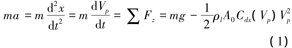
where m is the projectile mass;x is the axis;t is time; A0is the projected area of the projectile;ρlis the water density;Vpis the penetration velocity;Cdx=Cd0+σ[14]is the drag coefficient of the projectile;σ=2(ppv)/(ρlV2
p)is the cavitation number;p is the far field pressure;pvis the vaporization pressure of water;Cd0= 0.637[8]is the drag coefficient when σ=0 for the head shape used in this paper;g is gravitational acceleration.In this paper for high-speed water entry condition,the effect of g will be neglected,so Eq.(1)changes to:
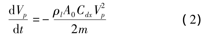
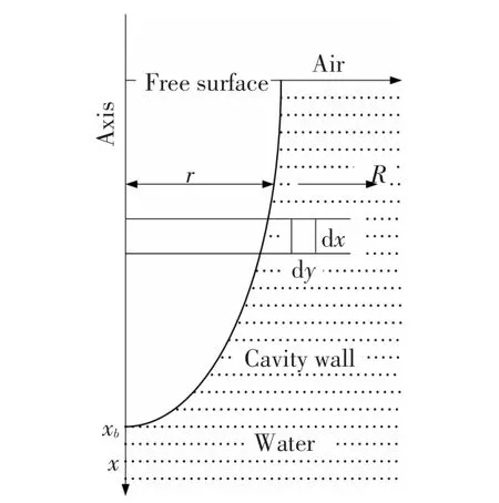
Fig.1 Analytical model
The rate of change of kinetic energy of the projectile with respect to depth xb,dEp/dxb,can be expressed as:
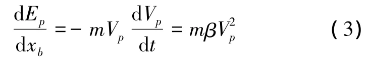
where β=ρlA0Cdx/2m;xbis the location of the head of the projectile.
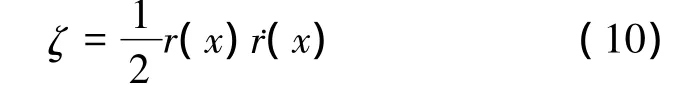
The radial velocity of the cavity wall can be expressed as the function of the source strength,ζ,in the axis,and is given by:
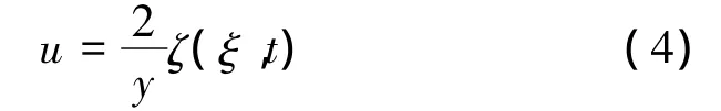
where ξ is the penetration depth.
For a finite section of water dx and within the disturbed fluid radius with a radius R.The kinetic of water,El,can be expressed as:
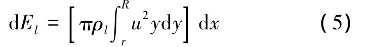
where r is the cavity radius at the penetration depth.
Substituting Eq.(4)into Eq.(5)and integrating yields:
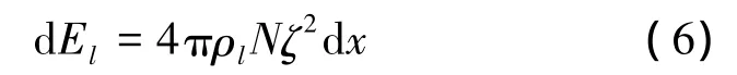
where N =ln(R/r)is a dimensionless geometric parameter.Lundstrom used N=ln15 to solve the problem of subsonic projectiles,in this paper,we use N=ln 30.
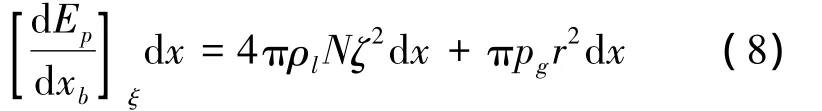
Another part of the energy transformation is the potential energy which is stored in the fluid due to the expansion of the cavity walls.For a finite volume πr2dx,the potential energy can be expressed as:

where pg=p(x)-pc(x)for simplicity;p(x)is the hydrostatic pressure in the fluid section;pc(x)is the pressure in the cavity at depth x,and in this paper,we assume that the cavity is full of vapor,then we use pc(x)=3540 Pa.So,according to the conservation of the energy,we can obtain:
By introducing the variables A(x)and B(x)given byandobtain:

From Eq.(4),we can obtain:
by substituting the boundary condition uy=r=˙r(x)on the cavity wall.
Combining Eqs.(9)and(10),and then integrating with the boundary condition r(x)is the total time the projectile traveled,we can obtain the expression of cavity radius at depth x:
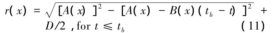
By Eq.(11),if we fix tb,for a given random time t=tr,we can obtain the radius of the cavity at the depth x(t)=x(tr)at the time of tb,then we can obtain the shape of the cavity wall at the time tb.
3 Numerical Simulation
3.1 Governing Equations
In this section, the fluid is assumed as incompressible and the thermal effect is neglected.The VOF multiphase model is introduced to solve the viscous cavitating flows;αl,αg,αvare used to be the volume fractions of liquid,gas and vapor phases respectively,and the values satisfy the equation:

The continuity and momentum equations are given by Eqs.(13)and(14):
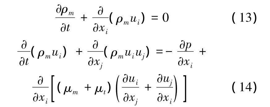
where ρmis the mixture density;uiand ujare the velocity vectors;p is the pressure;μmis the mixture viscosity;μt=ρmCμk2/ε is the turbulent viscosity.The mixture density ρm,mixture viscosity μmare expressed as:
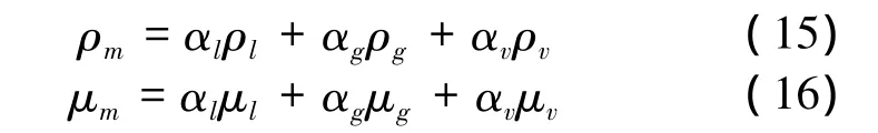
where ρl,ρgand ρvare densities of liquid,gas and vapor phases respectively.
The control equations of vapor volume fraction can be expressed as:
where RB=1e-6 m is the radius of the bubble;αnuc= 5e-4 is the nucleation site volume fraction;Fvap=50 and Fcond=0.001 are the empirical evaporation and condensation coefficients respectively.
3.2 Turbulence Model
In this paper,k- ω SST turbulence model proposed by Menter[15]by combining the advantages of k-ε and k-ω turbulence model is implemented to provide turbulent closure,which are expressed as:
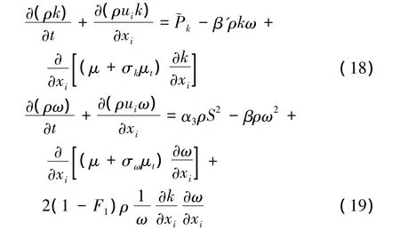
where F1is a blending functionβ'ρkω),with:
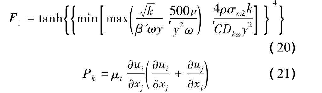
The turbulent eddy viscosity is defined as:
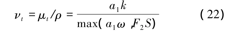
where S is the invariant measure of the strain rate and F2is another blending function can be expressed as:
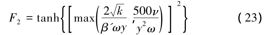
All constant values are obtained from corresponding constants of the k-ε and the k-ω model such as α3=α1F+α2(1-F).The values of the constants are:β'=0.09,α1=5/9,α2=0.44,β1= 3/40,β2=0.0828,σk1=0.85,σk2=1,σω1=0.5,σω2=0.856.
3.3 Computational Methodology and Problem Description
A high-speed water entry of a cone-cylinder with an initial penetration velocity of 500 m/s is considered. For numerical simulation, we use FLUENT based on the governing equations to solve this problem.The governing equations are discretized by using the FiniteVolumeMethod,and thePISO algorithm isused to solvingthe pressure-velocity coupling fields.The volume fractions of the phases are discretized by using CICSAM.
The configurations of the cone-cylinder projectile and computational domain are illustrated in Fig.2(a),D=10 mm is diameter of the cylinder part and we use r0here as the radius of the cylinder part,the length of the cylinder,L=5D,the half angle of the cone head is 63.5 degree.According to Section 2,for this twodimensional axis-symmetric problem,we choose x to be the axis,and+x is the penetration direction;y is the radial direction the diameter of the fluid is 100 D,and the projectile penetrates vertically from2D height above the water surface.The mesh around the projectile is illustrated in Fig.2(b).
Fig.2 Problem illustration
The densities of water,air and projectile are 998.2 kg/m3, 1.225 kg/m3, 2700 kg/m3respectively,and the operating temperature is 300 K and the saturation pressure is 3540 Pa.
4 Results and Discussion
4.1 Results Comparison of the Two Methods
Both of the two methods are introduced to solve the same problem with the same projectile and boundary conditions.Foranalyticalmethod,the velocity Vpat all time steps can be obtained by solving Eq.(2),and the trajectory of the projectile are also obtained by integrating Vp.Fig.3 shows the time histories of velocities and trajectory which are obtained by the two methods.
Fig.3 Comparison of numerical and analytical results
From Fig.3,it can be found that the variations of penetration velocity and trajectory are exactly the same comparing the two results.However,there are still deviations between the values,and the results obtained by analytical method are slightly larger than the results obtained by numerical simulation for both penetration velocity and trajectory.As is known,the trajectory of a projectile totally depends on its velocity,and from Fig.3 we can find that the velocity decays faster of the numerical results than that of the analytical results,and it's mainly because the analytical model considers the projectile as a cylinder with a given Cdbut not the cone head,then the computation will not be under the same condition,especially for the early stage of water entry,which has the most complicated events for both above and below the water surface.However,in this high-speed water entry problem,the error limits we obtained in Fig.3 are acceptable.From Fig.3,we can also find that the velocity of the projectile decays rapidly,it loses about 90%in 6 ms,within 80D deep under the water surface.So it will be an important problem that how to decrease drag forces,in particular for naval weapon applications.
In the other hand,the results of cavity shapes at various depths are analyzed.The results of the two methods are shown in Fig.4.
From Fig.4,it can be clearly seen that the results of the cavity shapes at each penetration depth agree well below the water surface.For the two methods solve different equations,there are deviations near the original water surface.Firstly,the analytical model neglects the splash formed during the penetration and the uplift of the water surface.Secondly,from the numerical results we can find that,the cavity wall nears the original water surface contracts to the axis at the influence of atmospheric pressure and surface tense.
Fig.4 Comparison of the cavity shape
Through the comparison of the results,the numerical method was considered to be valid to simulate this problem here presented.The numerical results are presented as follows.
4.2 Cavity Flows
4.2.1 Cavity shape
In this part,cavity shapes at specified penetration depths H(where H=10D,20D,30D,40D,50D) since water impact are given by Fig.5.It can be seen that in this time period,the cavity radius gets bigger when the projectile gets deeper,at the depth of 50D,the maximum radius reaches to 12r0.However,the cavity radius does not appear to expand so quickly near the water surface compares to the expansion of the cavity wall under the water surface.It can be seen that before the depth of 30D,the cavity is open and the splash gets higher and shows a trend of contraction,then the splash is about to get closed.When the projectile reaches the depth of 50D,the radius of the splash shows little deviations compares to at the depth of 40D,and the splash closed at this time.
Fig.5 Cavity formation during the penetration
4.2.2 Pressure field
Fig.6 shows the contour of absolute pressure at specified depths.It can be found that the lowest pressure appears inside the cavity,almost the same as the evaporation pressure,this means cavitation occurs in the cavity during the penetration.The far field pressure keeps steady at a medium level.The largest pressure appears in the contact area between the projectile and water,as the projectile gets deeper,the pressure acts on the tip of the cone decays because of the decay of penetration velocity.In order to figure out the process of cavitating and the variation of the pressure,the vapor volume fraction in the cavity were illustrated in Fig.7,and the absolute and dynamic pressure act on the tip of the cone are also plotted in Fig.8.
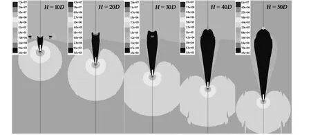
Fig.6 Contour of the absolute pressure distribution
Fig.7 shows the vapor phase generated during the penetration.It can be seen that in opening-cavity stage,the vapor phase comes up adjoins the cavity wall continuously as the projectile passes.After the splash closed,the splash resists the movement of the vapor into the air,so most of the vapor gathers in the top of the cavity,and the closed cavity then happens to be a space of mixture phases of vapor and air.
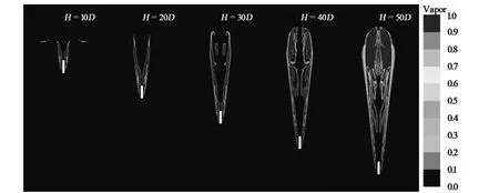
Fig.7 Contour of vapor volume fraction
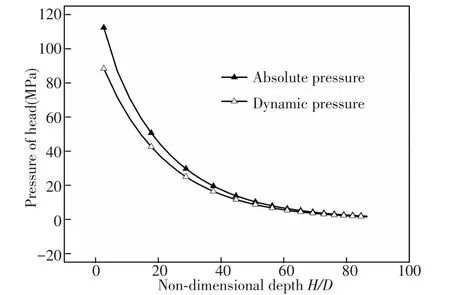
Fig.8 Pressure acts on the tip of the cone
From Fig.8,we can find that the absolute pressure act on the tip of the cone is extremely high at the beginning of the penetration,which reaches 110 MPa.As the projectile gets deeper,the velocity decays and the dynamic pressure gets smaller as well as the absolute pressure;when the projectile reaches the depth of 80D,it's only about 1-2 MPa.So,for the applications of naval weapons,in case of the high pressure,the materialchoosing should be well considered for the structural stability of the projectile.
4.2.3 Streamline of cavity flow
As is known,cavitation occurs during the highspeed water entry process,and the mixture in the cavity consists of vapor and air.In this part,the cavitating flow is taken into account.
Fig.9 shows the contours of streamlines and the air volume fraction at specified depths.It can be found that before the splash closes,the cavity volume gets bigger when the projectile gets deeper,except the generation ofvapor,the airoutside continuously supplies the cavity,for the pressure inside the cavity is much lower than the outside where is atmospheric pressure.However,after the splash closes,as we obtained in the last part,there isn't any air could come into the cavity,so the air outside above the water surface can only moves up by the effect of uplift of the water surface.
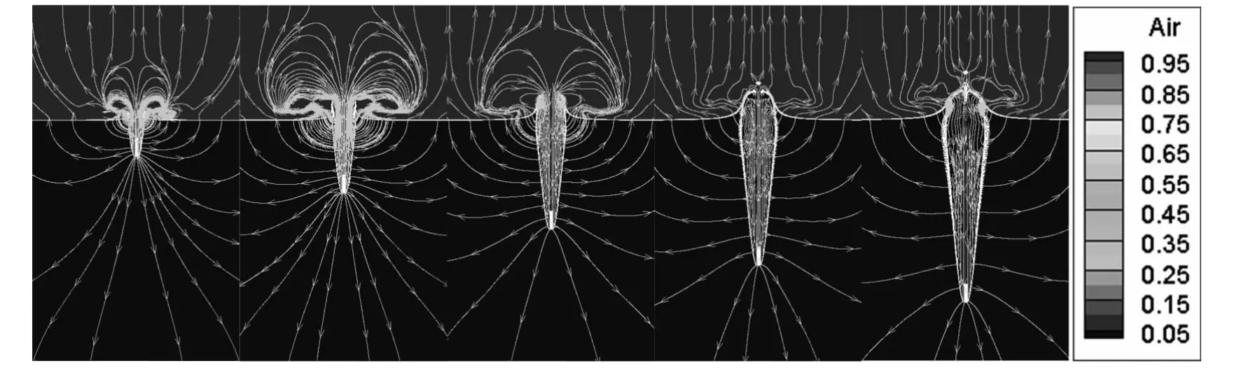
Fig.9 Streamline of the flow area
5 Conclusions
Both numerical simulation and analytical method are used to solve high-speed water entry problem of a cone-cylinder projectile,and the results of the two methods agree well.Numerical results show that the water entry cavity expands as the projectile moves deeper before the cavity gets a deep closure.During the penetration,the pressure acts on the tip of the cone is extremely high,which may lead to structural damage,especially in the initial stage of penetration. Because of the high-speed of the projectile,the pressure inside the cavity is much low and causes vapor generation.In the opening-cavity stage,the air outside moves into the cavity continuously.After the splash gets a surface closure,the air outside is resisted and the vapor phase is still generated and gathers in the top of the cavity.
[1]Worthington A M,Cole R S.Impact with a liquid surface studied by the aid of instantaneous photography.Philosophical Transactions of the Royal Society,1900,194 (A):175-200.
[2]Richardson E G.The impact of a solid on a liquid surface.Proceedings of the Physical Society of London,1948,61 (4):352-366.
[3] National DefenseResearchCommittee.Mathematical studies relating to military physical research.Summary Technical Report of the Applied Mathematical Panel,NDRC.Washington:NDRC,1946.
[4] Gilbarg D,Anderson R A.Influence of atmospheric pressure on the phenomena accompanying the entry of spheres into water.Journal of Applied Physics,1948,9 (2):127-139.
[5]May A,Woodhull J C.Drag coefficients of steel spheres entering water vertically.Journal of Applied Physics,1948,19(12):1109-1121.
[6]May A,Woodhull J C.The virtual mass of a sphere entering water vertically.Journal of Applied Physics, 1950,21(12):1285-1289.
[7]May A.Effect of surface condition of a sphere on its waterentry cavity.Journal of Applied Physics,1951,22(10): 1219-1222.
[8]May A.Water Entry and the Cavity-Running Behavior of Missiles.AD A020429.Silver Spring,MD:NAVSEA Hydroballistics Advisory Committee,1975.
[9]Lundstrom E A.Fluid Dynamic Analysis of Hydraulic Ram.Report No.NWC TP 5227.China Lake,CA:Naval Weapons Center,1971.
[10]Lee M,Longoria R G,Wilson D E.Cavity dynamics in high-speed water entry.Physics of Fluids,1997,9(3): 540-550.
[11]He C,Wang C,Wei Y,et al.Numerical simulation of pressure distribution in vertical water-entry cavity.Journal of Ship Mechanics,2011,9:004.
[12]Wang C,He C,Quan X,et al.Numerical simulation of the influence of atmosphericpressureon water-cavity formed by cylinder with vertical water-entry.Journal of Harbin Institute of Technology,2012,44(5):14-19.
[13]He C,Wang C,Min J,et al.Numerical simulation of early air-cavity of cylinder cone with vertical water-entry.Engineering Mechanics,2012,29(4):237-243.
[14]Sedov L I.Two-Dimensional Problems in Hydrodynamics and Aerodynamics.New York,London,Sydney:John Wiley&Sons Inc.,1965.
[15]Menter F R,Kuntz M,Langtry R.Ten years of industrial experience with the SST turbulence model.Turbulence,Heat and Mass Transfer,2003,4:625-632.
 Journal of Harbin Institute of Technology(New Series)2014年3期
- Journal of Harbin Institute of Technology(New Series)的其它文章
- Aerodynamic Characteristics of Projectile with Exotic Wraparound Wings Configuration
- Intelligent Temperature Control System Design Based on Single-Chip Microcomputer
- Influence of Punch Shape on the Fracture Surface Quality of Hydropiercing Holes
- Synchronization of High-order Discrete-time Linear Complex Networks with Time-varying Delays
- Simulation Platform of Underwater Quadruped Walking Robot Based on MotionGenesis Kane 5.3 and Central Pattern Generator
- Backstepping Adaptive Controller of Electro-Hydraulic Servo System of Continuous Rotary Motor