
Simulation Platform of Underwater Quadruped Walking Robot Based on MotionGenesis Kane 5.3 and Central Pattern Generator
2014-03-14 06:45:56KeYangXuYangWangTongGeChaoWu
Ke Yang,Xu-Yang Wang,Tong Ge,Chao Wu
(School of Naval Architecture,Ocean and Civil Engineering,Shanghai Jiaotong University,Shanghai 200240,China)
1 Introduction
Multi-legged robot locomotion has been an area of keen interest to the researchers over the years because of the advantages of the superior mobility in irregular terrain and the less hazardous influences on environment comparing with the wheeled robots[1].It introduces more flexibility and terrain adaptability at the cost of low speed and the increased control complexity[2].In order to develop dynamic model and control algorithm of legged robots,it is important to have good models which can describe the kinematic and dynamic behavior of the complex multi-legged robotic mechanism[2].Soyguder et al.[3]constructed a spring loaded inverted pendulum model of a quadrupedal pronking gait robot.Agarwal et al.[4]presented a detailed model of realistic four-legged robot.Wang et al.[5]analyzed the kinematics and dynamics of a quadruped walking robot with parallel leg mechanism.Poulakakis et al.[6]compared the models and experiments involving Scout II,an untethered fourlegged running robotwith only one actuatorper compliant leg.Remy et al.[7-8]applied the principles of passive dynamic walking onto the three-dimensional motion of a simplified quadrupedal model.However, the dynamic model of underwater quadruped walking robot based on Kane dynamic equations is still leaking.In thispaper,the Kane dynamic modelofthe underwater quadruped walking robot was constructed to be processed with a commercial package MotionGenesis Kane 5.3.
The control strategy for walking robots must take a series of factors into account[9],of which are noted: speed,walking stability,form and consistence of terrain.Iida et al.[10]exploited the body dynamics to control the behavior of quadruped robot.Kurazume et al.[11]presented feedforward and feedback dynamic trot gait control for quadruped walking robot.Maufroy et al.[12]intended to show the basis of a general legged locomotion controller with the ability to integrate both posture and rhythm motion controls and shift continuously from one control method to the other according to the walking speed.Buchli et al.[13]presented adaptive controller which consisted of adaptive frequency oscillators in different configurations and produced dynamic gaits such as bounding and jumping.Kimura et al.[14-16]made a quadruped robot walk with medium speed on irregular terrain in an outdoor environment by using a neural system model.The control strategies proposed above were successfully used to control the quadruped robot walking on land, but the control strategies which can be used to realize adaptive walking in underwater environment is still leaking.
In this paper,the Kane dynamic model of underwater quadruped walking robot is constructed,which can be processed with a commercial package MotionGenesis Kane 5.3. Then, a CPG-based controller is proposed,which can be used to control the walking of the underwater quadruped walking robot.Finally,a simulation platform is constructed for an underwater quadruped walking robot based on Kane dynamic model and CPG-based controller.In our simulation platform,it needs to investigate:how CPG parameters and coefficients of spring and damper affect the walking speed of the underwater quadruped walking robot.Walking with maximum speed is implemented in our simulation platform.
2 Dynamic Model
2.1 Mechanical System
In this section,the mechanical system of the underwater quadruped walking robot is described.The robot consists of nine segments which are concatenated one dimensionally via joints.A motor is mounted onto each joint,and thus,each joint can be independently controlled.Fig.1 shows the segment of the underwater quadruped walking robot.
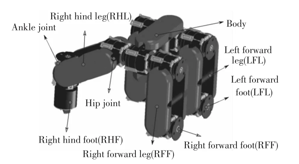
Fig.1 Underwater quadruped walking robot
2.2 Hydrodynamic Forces
The hydrodynamic forces acting on the underwater quadruped walking robot include:buoyancy,drag force and drag moment,add mass force and add mass moment.As shown in Fig.1,the body of underwater quadruped walking robot is rectangular box;the leg of underwater quadruped walking robot consists of two rectangular boxesand one cylinder;the footof underwater quadruped walking robot is cylinder.So,it just needs to deduce the formula of hydrodynamic forces of rectangular box and cylinder.The geometric parameters are shown in Table 1.
The hydrodynamic forces of rectangular box have been introduced in Ref.[17].So,it just introduces formulas of hydrodynamic forces of cylinder.The buoyancy is proportional to the mass of the fluid displaced by cylinder through the center of buoyancy of cylinder.

where ρ is the density of the fluid;V is the volume of the fluid displaced by cylinder.
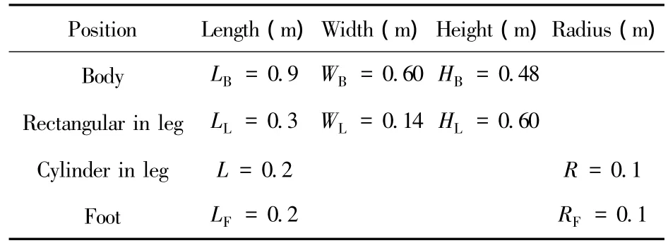
Table 1 Geometric parameters of underwater quadruped walking robot
The drag force and drag moment can be expressed as follows[18]:
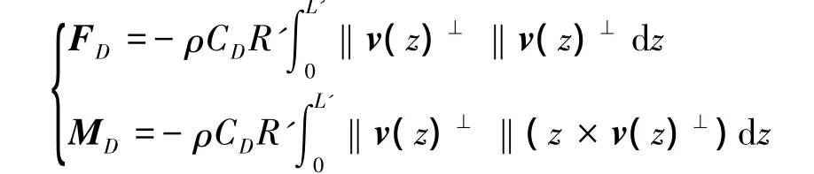
where FDis drag force;MDis drag moment;CDis drag coefficient;R'is the radius of cylinder;L'is the length of cylinder;v(z)⊥represents the translational velocity relative to the fluid and normal to z direction along the length of cylinder.
The added inertia forces and moments acting on the cylinder due to the motion of the surrounding fluid are expressed in the vector form as[17]:
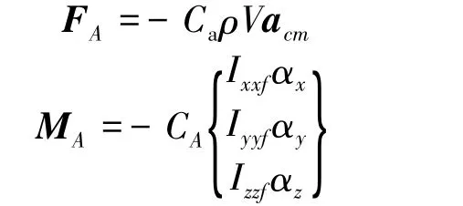
where Cais the added mass coefficient;CAis the added inertia moment coefficient;ρV is the mass of the fluid with the same volume of the cylinder;Ixxf,Iyyf,and Izzfare the central moment of inertia of the fluid with the same volume ofthe cylinder;acmisthe linear acceleration of the center-of-mass(cm)of cylinder; α= [αxαyαz] is the angular acceleration of cylinder.
2.3 Model Description
An outline of the model structures is described in Section 2.3.1.More detailed explanations regarding how to represent those structures in the MotionGenesis Kane 5.3 are discussed in later sections.
2.3.1 Outline of the model
The model has nine rigid body segments in total: B(Body),LFL,LFF,RFL,RFF,LHL,LHF,RHL,RHF(as shown in Fig.1).Those segments are interconnected with joints.The body has 6 degree of freedom(DOF)(3 translations and 3 rotations).The joint has 1 DOF.The total number DOF of the robot model is 14.The adjacent segments are noted by“joint”(for example,LFH,LFA etc.),as shown in Fig.2.The model has eight joints in total:LFH,LFA,RFH,RFA,LHH,LHA,RHH,and RHA.
The global(inertia)coordinate system is named“N”(Fig.2).Each segment has a local coordinate system attached to the end of the segment.Two vectors that compose the coordinate system are named as“(segment name)(x>,y>or z>)”(for example,LFLx>,LFLy>,LFL z>for the left forward leg; Fig.2).J represents the end of foot.The generalized coordinates of the system are defined as:

The segment except body and the jointare represented by three characters.The meaning of each character is shown in Table 2.
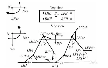
Fig.2 Schematic diagram of underwater quadruped walking robot
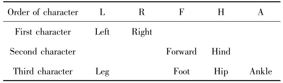
Table 2 Meaning of character
2.3.2 Constraint conditions
Linkage of segments,i.e.,relative relations of segments,has been determined as shown in Tables 3 and 4.The relative relations between body and legs can be represented by the similar way.So,it just depicts the relative relations of body,left forward leg (LFL),and leftforward foot(LFF).“Bcm”represents center-of-mass of body.“No”represents the origin of the global(inertia)coordinate system“N”.
Table 5 shows how depict forces and moments act on the underwater quadruped walking robot.For ease of description,left forward leg(LFL)is taken as an example.Table 5 just includes typical forces and moments acted on the LFL.The rest forces and moments acted on the LFL can be dealt with the same way.mLis the mass of leg.Ix,Iy,and Iz are the central moment of inertia of leg.
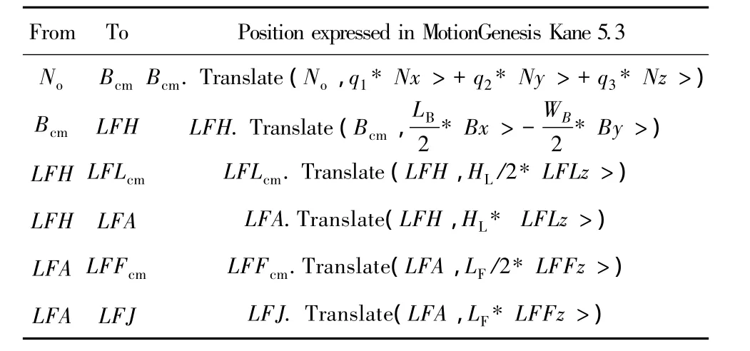
Table 3 Position constraint
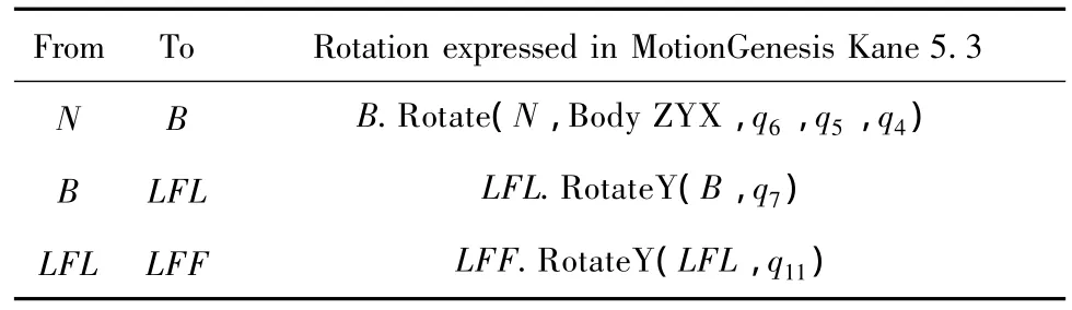
Table 4 Rotation constraint
2.3.3 Contact force between foot and ground
The ground reaction forces rely on the interaction between feet and floor because the contact point changes in every step.To solve this problem,the ground reaction forces are represented as a spring and damper acting at the feet.The ground reaction forces in Nx>and Nz>direction are given as:

where(xf,zf)is the coordinate of the end of foot;(x0,z0)is the origin coordinate when the foot contact with ground;kpx,kpzare coefficients of spring;kdx,kdzare coefficients of damper.
Fig.3 shows the relation between zfand the coefficients of spring and damper in Nz>direction when underwater quadruped walking robot is static.From Fig.3,it can be seen that zfdecreases slowly when kpzchanges from 2000 to 20000(kdzis fixed),and zfalmost no change when kdzchanges from 1000 to 10000(kpzis fixed).The minimum value of zfis 0.0041 m(zf=0 represents the ground).Fig.4 shows how kdzaffects the rate of convergence.
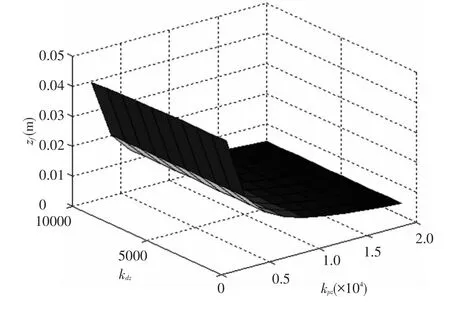
Fig.3 Relation between zf,kpzand kdz

Fig.4 Relation between kdzand the rate of convergence
3 CPG-based Controller
In this section,a CPG-based controller for legs based on CPG and PD controller is constructed.CPG provides the target angles of legs for PD controller,and actual angles,which come from dynamic model,provide feedback for PD controller.
3.1 CPG Model
A CPG model consists of two mutually inhibiting neurons.Each neuron in this CPG modelis represented by the following nonlineardifferential equations[15]:
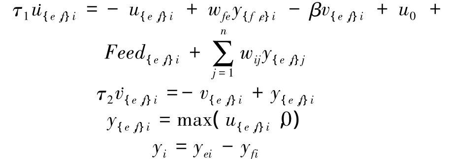
where u{e,f}iis the membrane potentials of an extensor neuron or a flexor neuron in the ith CPG model;v{e,f}iis the variable that represents the degree of adaptation; τ1and τ2are the time constants;β is the adaptation coefficient;u0is the tonic driving input;wfeis a connecting weight between extensor and flexor neurons;wijis the connecting weight between ith CPG modeland jth CPG model;Feed{e,f}irepresents feedback signal from the robot;y{e,f}iis output of extensor or flexor neurons in the ith CPG model;yiis the output of ith CPG model.The output amplitude of CPG keeps a linear relation with u0[19];the output period of CPG keeps a linear relation with τ1while the value of τ1/τ2is constant[19].
3.2 CPG-based Controller
For a quadruped walking robot,the CPG network is constructed through connecting four CPG modules,each of which provides a target angle for a hip joint of a leg.And a trot gait for walking is chosen.For diagonal legs,the CPG module generates target angle with 0° phase difference;otherwise, the CPG module generates target angle with 180°phase difference(as shown in Fig.5).The oscillation periods of CPG model are equal.The trot gait can be obtained through adjusting the parameter wij.
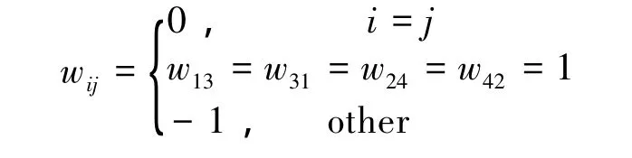
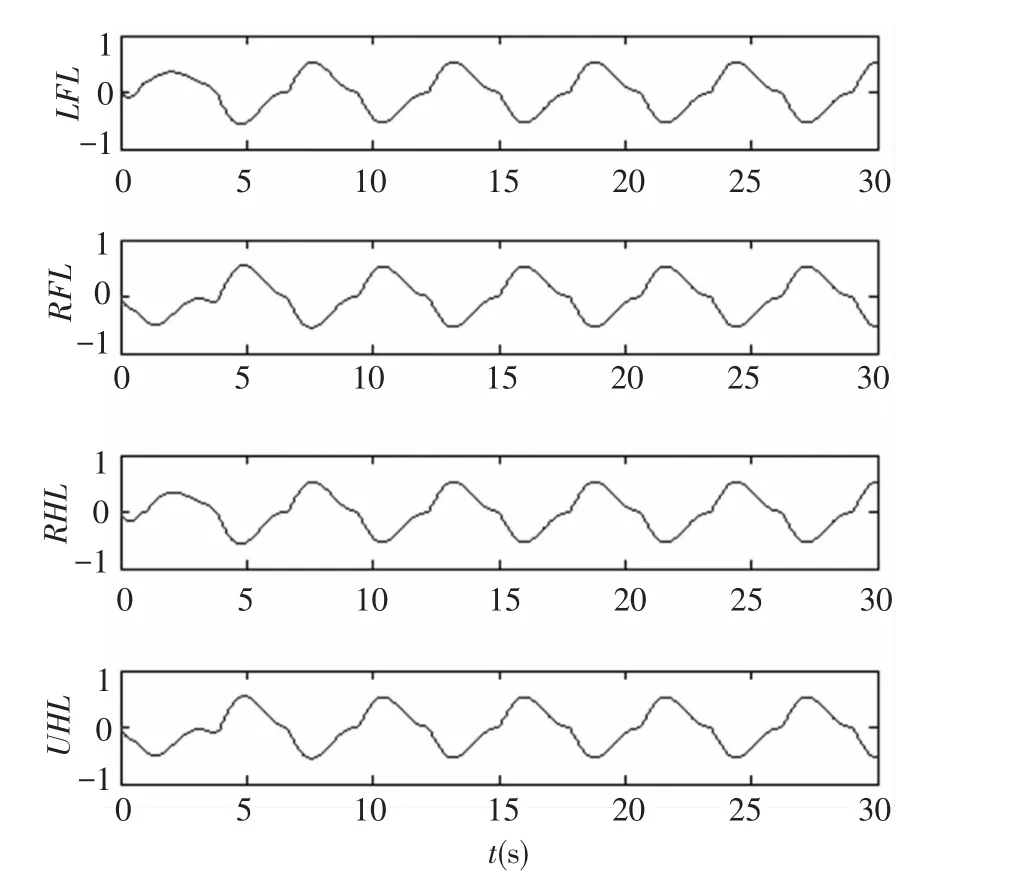
Fig.5 Target angles of legs come from CPG
In the following experiments,the hip joints are controlled by CPG-based controller, but, for simplicity,the ankle joints are controlled by PD-controller(as shown in Fig.6).The angle of ankle joint qi(i=11,12,13,14)can be expressed as:

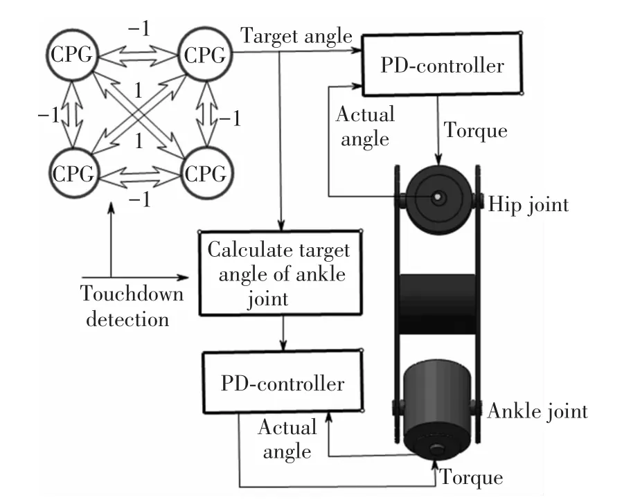
Fig.6 CPG-based controller
4 Simulation
In this section,it investigates the relation between the coefficients of spring and damper and walking speed of underwater quadruped walking robot,the relation between CPG parameters and walking speed of underwaterquadruped walking robot. Itrealizes walking with maximum speed of underwater quadruped walking robot on the underwater flat ground.
4.1 Effect of Coefficients of Spring and Damper
Fig.7 shows the relation between velocity of Bcmand coefficients of spring and damper in Nz>direction when kpzchanges from 2000 to 20000 and kdzchanges from 1000 to 10000.The maximum velocity of Bcmis 0.27 m/s,which is obtained at the point(kpz=4000,kdz=1000).
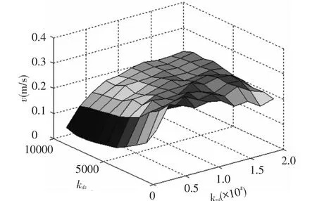
Fig.7 Relation between velocity of Bcmand coefficients of spring and damper in Nz>direction
Fig.8 shows how coefficients of spring and damper in Nx>direction affect the velocity of Bcm(kpz=4000,kdz=1000).When kpxvaries from 400 to 4000 and kdxvaries from 200 to 2000,the maximum velocity of Bcm(v=0.29 m/s)is obtained at the point(kpx=2800,kdx=800).
4.2 Effect of CPG Parameters
Fig.9 shows how CPG parameters affect the velocity of Bcm(τ1/τ2=1/3,kpx=2800,kdx= 800,kpz=4000,kdz=1000).When u0changes from 0.2 to 2 and τ1changes from 0.05 to 0.6,the maximum velocity of Bcm(v=0.34)is obtained at the point(u0=1.4,τ1=0.15).
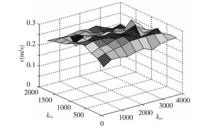
Fig.8 Relation between velocity of Bcmand coefficients of spring and damper in Nx>direction

Fig.9 Relation between velocity of Bcmand CPG parameters
4.3 Walking with Maximum Velocity on Underwater Flat Ground
Fig.10 shows the trajectory of Bcmin Nx>direction when the underwater quadruped walking robot walk with the maximum velocity on the underwater flat ground.
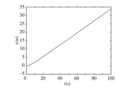
Fig.10 Trajectory of Bcmin Nx>direction
Fig.11 shows the change of trajectory of Bcmin Nz>direction(the initial value is Z=-0.8 m).Alternating movement of legs will lead to the change of Bcmin vertical direction.The touch between feet and ground also induces the change of Bcm.That is because the forces between feet and ground are represented as a spring and damper,and the feet will fall into ground when the feet contact with the ground.

Fig.11 Trajectory of Bcmin Nz>direction
5 Conclusions
In this paper,a simulation platform is constructed for an underwater quadruped walking robot based on Kane dynamic model and CPG-based controller.The Kane dynamic model of the underwater quadruped walking robot is processed with a commercial package MotionGenesis Kane 5.3. The function of the simulation platform can be described as:
1)Researching the relation between coefficients of spring and damper and stability of the underwater quadruped walking robot;
2)Researching the relation between CPG parameters and adaptive walking of underwater quadruped walking robot;
3)Researching how CPG parametersand coefficients of spring and damper affect the walking speed of underwater quadruped walking robot;
4)Researching how hydrodynamic coefficients affect the walking speed of underwater quadruped walking robot.
In this paper,it mainly studies two questions:in the stationary state,the relation between coefficients of spring and damper in Nz>direction and stability of underwater quadruped walking robot;in the motion state,the effect of CPG parameters and coefficients of spring and damper on walking speed of the underwater quadruped walking robot.The simulation results show that the simulation platform can imitate the stable walking of the underwater quadruped walking robot.
[1]Mahapatra A,Roy S S.Computer aided dynamic simulation of six-legged robot.International Journal of Recent Trends in Engineering,2009,2(2):146-151.
[2]Roy S S,Singh A K,Pratihar D K.Analysis of six-legged walking robots.Proceedings of the 14thNational Conference on Machines and Mechanisms.Durgapur:International Federation of the Theory of Machines and Mechanisms (IFToMM),2009.259-265.
[3]Soyguder S,Alli H.Computer simulation and dynamic modeling of a quadrupedal pronking gait robot with SLIP model.Computer and Electrical Engineering,2012,38 (1):161-174.
[4]Agarwal S,Mahapatra A,Roy S S.Dynamics and optimal feet force distributions of a realistic four-legged robot.International Journal of Robotics and Automation,2012,1 (4):223-234.
[5]Wang H B,Sang L F,Hu X,et al.Kinematics and dynamics analusis of a quadruped walking robot with parallel leg mechanism.Chinese Journal of Mechanical Engineering,2013,26(4):1-11.
[6] Poulakakis I,Smith J A,Buehler M.Modeling and experiments of untethered quadrupedal running with a bounding gait:the scout II robot.The International Journal of Robotics Research,2005,24(4):239-256.
[7]Remy C D,Hutter M,Sierwart R.Passive dynamic walking with quadrupeds —extensions towards 3D.Proceedings of IEEE International Conference on Robotics and Automation.Piscataway:IEEE Computer Society,2010.5231-5236.
[8]Remy C D,Buffinton K,Siegwart R.Stability analysis of passive dynamic walking of quadrupeds.The International Journal of Robotics Research,2010,29(9):1173-1185.
[9]Vladareanu L,Melinte D O.Dynamic force-position control of the walking robots motion on slope.Applied Mechanics and Materials,2012,186(1):98-104.
[10]Iida A,Gomez G,Pfeifer R.Exploiting body dynamics for controlling a running quadruprd robot.Proceedings of 12thInternational Conference on Advanced Robotics.Piscataway:IEEE Computer Society,2005.229-235.
[11]Kurazume R,Yoneda K.Feedforward and feedback dynamic trot gait control for quadruped walking vehicle.Autonomous Robots,2002,12(2):157-172.
[12]Maufroy C,Kimura H,Takase K.Integration of posture and rhythmic motion controls in quadrupedal dynamic walking using phase modulations based on leg loading/ unloading.Autonomous Robots,2010,28(3):331-353.
[13]Buchli J,Ijspeert A J.Self-organized adaptive legged locomotion in a compliant quadruped robot.Autonomous Robots,2008,25(4):331-347.
[14]Fukuoka Y,Kimura H,Cohen A H.Adaptive dynamic walking of a quadruped robot on irregular terrain based on biological concepts.The International Journal of Robotics Research,2003,22(3/4):187-202.
[15]Kimura H,Fukuoka Y,Cohen A H.Adaptive dynamic walking of a quadruped robot on natural ground based on biological concepts.The International Journal of Robotics Research,2007,26(5):475-490.
[16]Kimura H,Fukuoka Y,Konaga K.Adaptive dynamic walking of a quadruped robot using a neural system model.Advanced Robotics,2001,15(8):859-878.
[17]Safak K K,Adams G G.Dynamic modeling and hydrodynamic performance of biomimetic underwater robot locomotion.Autonomous Robots,2002,13(3):223-240.
[18]Tran T J,Shoults G A,Yang S P.A dynamic model of an underwater vehicle with a robotic manipulator using Kane’s method.Autonomous Robots,1996,3(2/3):269-283.
[19]Wu X D,Ma S G.Adaptive creeping locomotion of a CPG-controlled snake-like robot to environment change.Autonomous Robots,2010,28(3):283-294.
 Journal of Harbin Institute of Technology(New Series)2014年3期
- Journal of Harbin Institute of Technology(New Series)的其它文章
- Aerodynamic Characteristics of Projectile with Exotic Wraparound Wings Configuration
- Numerical Simulation of High-Speed Water Entry of Cone-Cylinder
- Intelligent Temperature Control System Design Based on Single-Chip Microcomputer
- Influence of Punch Shape on the Fracture Surface Quality of Hydropiercing Holes
- Synchronization of High-order Discrete-time Linear Complex Networks with Time-varying Delays
- Backstepping Adaptive Controller of Electro-Hydraulic Servo System of Continuous Rotary Motor