
Millau viaduct geotechnical studies and foundations
2013-06-05 14:54ShlosserServantGuillouxBergereaENPCFrane
F. Shlosser, C. Servant, A. Guilloux, A. BergereaENPC, Frane
bEiffage Travaux Publics, France
cTerrasol, France
Millau viaduct geotechnical studies and foundations
F. Schlossera,∗, C. Servantb, A. Guillouxc, A. Bergerec
aENPC, France
bEiffage Travaux Publics, France
cTerrasol, France
ARTICLE INFO
Article history:
Received 26 March 2013
Received in revised form 1 May 2013
Accepted 15 May 2013
Cable stayed bridge
Foundation design
Pile settlement
Rotation
Observational method
The Millau viaduct over the Tarn River is an exceptional bridge considering the height under the deck and the 2.5 km total length. Each of the seven high piers is founded on a thick raft setting on four large piles of 5 m in diameter and 10–15 m deep. The ground schematically consists of limestone in the north and of marls in the south. As the bridge is very sensitive to foundation settlements, the concessionary company decided to use the observational method for controlling the displacements and if necessary stabilize the foundations. The measurements show that the movements have remained small and admissible, particularly in terms of the rotations. The settlements have not occurred continuously under the load, but by steps.
© 2013 Institute of Rock and Soil Mechanics, Chinese Academy of Sciences. Production and hosting by Elsevier B.V. All rights reserved.
1. Geological and geotechnical context
The Millau viaduct links two limestone plateaus separated by a deep valley eroded by the Tarn River. The sedimentary basins, which started to form during the middle of the Secondary Era, appear to be particularly well preserved. The Tarn has revealed the stratigraphy of the zone which shows Triassic formations at the bottom of the valley and then displays the full sequence up to the end of the Jurassic Era which is represented by the limestone at the top of the Larzac plateau to the south of the viaduct as shown on the right of Fig. 1.
The rock encountered on the site is exclusively sedimentary, composed partly of dolomitic limestone and partly of compact marls (Mennessier and Collomb, 1983).
A study of local tectonics shows that there are old faults which affect the older horizons in the sequence, back as far as the Lias. The old faults are located to the north of the viaduct but do not affect the more recent horizons of the geological structure of the top of the southern plateau, such as the Kimmeridgian stage. This typeof fault was specifically encountered by the northern abutment of the viaduct (C0) as shown in Fig. 1.
There are also some more recent non-active faults that affect the whole stratigraphy of the zone and cut across the viaduct site by pier P4 and again between pier P7 and the southern abutment C8 (Fig. 1). The strike slips on these faults, particularly where the pier P4 is located, have caused difficulties for the construction and have required an adaptation of the foundations.
Before starting the earthworks, the concession company and its public works contractor EIFFAGE TP systematically carried out additional geotechnical surveys of the soils to support the foundations by means of destructive drilling down to 10 m below the deepest level of the pile shafts and 15 m below the base of the foundation plates for the abutments.
As everyone knows, the main difficulty with rock mechanics is obtaining representative samples (Panet, 1976; Duncan, 1996). Laboratory tests carried out on small samples are not representative of the scale of all the discontinuities in the rock masses (especially the direction and size of the faults), which means that direct use of the results is not at all reliable. Thus the overall mechanical properties of a rocky block, generally assumed to be isotropic (φ, c: internal friction angle and cohesion, respectively; E: modulus of deformation) are more and more frequently determined by semi-empirical methods which combine geotechnical tests with geological observation of the borehole samples and existing outcrops (the RMR (rock mass rating) classification (Bieniawski, 1989) in accordance with the empirical method proposed by Hoek and Brown (1988) and Hoek et al. (1995)).
The RMR varies from 0 to 105. The mean values recorded on the Millau viaduct site are 65 for the limestone and 53 for the marls.

Fig. 1. Simplified geotechnical cross section of the viaduct.
There are three different types of foundation rocks along the viaduct. The first one, the Bajocian dolomitic limestone at the northern abutment (C0), is a very hard rock with an unconfined compressive strength Rc= 110 MPa but with karsts filled with clay. At the top of the platform where the raft was placed, a RMR value of 70–80 was determined.
The compacted marls from pier P7 to pier P6 constitute the second rock type. Slides are visible at the soil surface due to the 2 m thick scree layer underlain by soft clay above the marls. Laboratory tests have given: Rc= 10–15 MPa, E = 3–6 GPa, γ = 25 kN/m3. The mean values of shear strength have been determined in the 15 m thick top layer of marls: RMR = 45, c = 0.1 MPa, φ = 30°.
The Hettangian limestone on the two sides of the Tarn River from pier P4 to the abutment (C0) constitutes the third rock type. Its bedding is sub-horizontal on the south side and at a 10°/15°angle on the north side. The results from laboratory tests are: Rc= 50–70 MPa, E = 8 to 15 GPa, γ = 25 kN/m3. The determined shear strength values are: RMR = 65 to 70, c = 2.5 MPa, φ = 37°.
It can be concluded that the marls are less resistant than the limestone. It is the reason that the piles in marls are enlarged at their base and are longer than the piles in limestone (Fig. 2).
2. Foundation system
The viaduct design produced by the authorities defined and designed the foundation systems for the piers and abutments. Although the final system is based on the same principles, it varies slightly depending on whether a given bearing is located on limestone or on marls. The marls not only have weaker mechanical properties than the limestone, but also show superficial slide which affects the upper part.
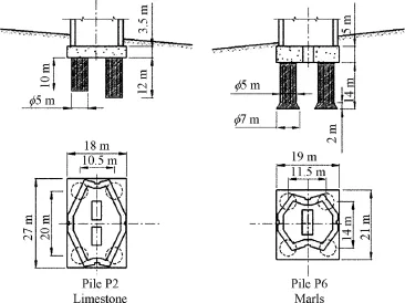
Fig. 2. Standard cross sections of piers in marls and limestone.
Spread foundations were chosen for abutments C0 and C8 which are founded on limestone. The foundation system is a monolithic set composed of a 1 m thick raft foundation for each front abutment, connected to two side footings for each rear abutment with the abutment platforms at different levels.
The foundation system (Fig. 2) for each of the 7 piers is composed of 4 reinforced-concrete piles with a diameter of 5 m and a depth of 10–15 m drilled in the rock and bonded together at the top by a 3.5 m thick reinforced-concrete footing, which is itself bonded to the pier. In marls, the footing is thicker and the piles deeper, with their base diameter being increased to 7 m.
Foundations of piers 2 and 6 have been taken as the typical examples in the present paper. The pier 2 is the highest one (245 m) and is founded in limestone, while the pier 6 is founded in marls and has a medium height.
The behaviour of this type of pier foundation system is complex. It is a piled raft foundation system in which part of the load is transferred to the footing. The way that this behaviour was simplified is particularly restrictive as it was assumed that firstly, the footing bears none of the load and secondly that no skin friction (qs= 0) is created along the shaft except in the case of tensile stress.
This comes down to assuming that bearing capacity depends solely on the ultimate pressure on the rock at the bottom of the shaft and that settlement results only from deformations of the rock at the bottom of the shaft, which makes the foundations more flexible than they really are.
Bearing capacity was de fined using standard Terzaghi equations adapted to take into account the inclination of the load and the proximity to the hillside, to which an overall stability calculation was added for shafts drilled in marly hillsides, as well as for the foundation of pier P3 in limestone whose overall stability had to be improved by a reinforced soil retaining wall (Tervoile).
With regard to settlement and foundation rotation subsequent to service loads (serviceability limit states), the calculation method used was the modulus of reaction to the behaviour hypotheses described above.
Several pile-loading trial tests were carried out in the marly soils to assess the skin friction along the shaft. Fig. 3 shows the results of one of these tests on a bored pile with a diameter of 0.80 m. Critical creep load at point Qcis approximately 5200 kN (qc= 10 MPa) for a shaft head settlement of 5.6 mm.
Despite the uncertainties regarding the assessment of the mechanical properties of the rock and the calculation methods used, the design for the pier foundations seems to be quite reliable.
3. Foundation design
To optimize the foundation design by using the observational method required iterations between the calculation results of the most probable behaviour of the foundation and the results of a constant monitoring during the construction. The overall stability of the foundation with regard to the proximity to the hillside was not to be optimized and a large safety factor was taken into account. As indicated before, a retaining structure has been constructed at pier P3 in order to increase the factor of safety. However the monitoring was also used to verify that for every pier no problem was encountered with regard to this stability.
The load bearing capacity and settlement of the foundations were calculated taking the least favourable combinations for the ultimate limit and serviceability limit states. Vertical load distribution was applied at the centre of the foundations to evaluate normal and horizontal strains and the longitudinal and transverse bending moments (Fig. 4) (Yu and Vayssade, 1991; Duncan, 1996). Wind load was examined separately (meteorology and wind tunnel tests).
Unlike the working assumption taken for the authorities’ design of the project, the construction calculations also took into account the behaviour of a piled raft foundation where part of the load is supported by the footing, and skin friction and tip resistance in the pile shafts are taken into consideration. This assumption, which is more like the actual behaviour, had to be adopted while the observational method was to be used.
The foundation system was designed by SETEC on the basis of the elastoplasticity calculated at the ultimate and serviceability limit states, modelling soil behaviour by means of springs positioned vertically beneath the pile shaft and horizontally along it. This design, which does not take into account either the bearing capacity of the footing or skin friction along the shaft, was requested by the concession management authorities for greater safety.
TERRASOL used its own software, FoXta, to study the foreseeable deformations of the piled raft foundation system and define vigilance and alarm levels for deformation (settlement and rotation), for permanent loads and for three types of loads (dead weight of piers, dead weight of piers and deck, permanent loads and maximum oblique wind load).
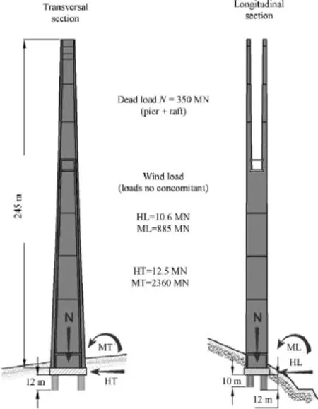
Fig. 4. Loads applied to pier P2.
In this calculation, the footing is assumed to be stiff and stiffness springs are applied at several points in order to simulate the ground and the shaft. The skin friction mobilization law is that of Frank and Zhao (1982) whilst the Young’s modulus for each geological layer of soil, which is assumed to be isotropic, is defined by the empirical equation (Hoek and Brown, 1988, 1996):

where RMR is the rock mass rating of the rocky layer, d is the rock decompression factor, and Rc(MPa) is the unconfined compressive strength.
The behaviour is different depending upon the ground conditions: in limestone, only 35% of the load is carried by the shafts, while in marls this ratio reaches about 90%. In addition, nearly 90% of the load transferred to the shaft is supported by the skin friction, whether the ground is limestone or marl. This shows that the shafts react very little at the base (Table 1).
4. Use of the observational method
From the outset, the concession-holding company, backed by its consultants and design and construction supervisor, adopted a cautious approach for the viaduct foundation design. The approach consisted primarily of using the observational method (Peck, 1969, 2002; Allagnat, 2005) to reduce areas of uncertainty and risk. It was continued throughout the construction of the viaduct and was composed of the following stages:
(1) Additional investigations for each pier, particularly by means of destructive drilling down to 10 m below the bottom of the pile shafts.
(2) Geotechnical monitoring of all earthworks (slopes and pile shafts), using the RMRs to validate or modify the initial geotechnical properties.
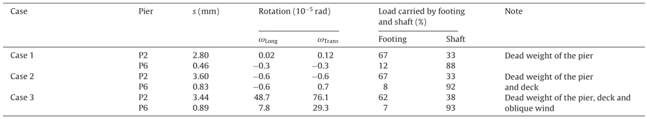
Table 1Settlement and rotation of foundations for piers P2 and P6 for three types of loads.
(3) Adaptation or even modification of pier and abutment foundations.
(4) Calculation of the serviceability limit state of the piled raft foundation of each pier for each type of load, based on newly identified rock properties and load transfer to the footing and skin friction along the shafts.
(5) Close supervision and monitoring of foundation movements during construction, combined with the definition of thresholds beyond which pre-defined reinforcement measures are to be implemented.
It should be noted that the observational method is not just a question of measurements; its purpose is to reduce areas of uncertainty by constantly comparing the forecasts and the actual behaviour during the monitoring process, and implementing reinforcement measures whenever the behaviour of the structure goes beyond certain levels.
Adapting the foundations principally involved: (1) turning the bearing foundation into deep foundations (abutment C0), (2) replacing with concrete a zone with weak mechanical properties, like faults or clay-filled karsts, (abutment C8, pier P4), (3) widening the base of some shafts to reduce differential settlement and improve load bearing capacity (pier P4), and (4) removing any contact between piers and slopes (pier P7).
The instrumentation installed for the observational method mainly consisted of markers on the four corners of each footing on the bases of the piers and clinometers. These allowed precise topographic measurements to be taken as well as spirit level measurements. Measurements were taken every month during viaduct construction.
Two types of thresholds have been defined: (1) a vigilance level beyond which measurements must be taken at short intervals to confirm the evolution of the displacements, and (2) an alert level at which pre-defined reinforcement measures are to be implemented (Table 2). A distinction has been made in the displacements between the average settlement “s” of the footing and its rotation“ω”.
With regard to the vigilance level for footing rotation, it was agreed that the threshold would represent a very cautious degree of displacement at deck level. The limit was thus set at a rotation ω = 5 × 10⁻⁴rad.
The alert level is reached when a series of measurements at short intervals over a period of one to two months confirms that the vigilance level has been exceeded. During this period, specific investigations were carried out at the pier foundation in order to identify the problem and adapt the reinforcement workaccordingly. The reinforcement measures depended on the problem encountered.
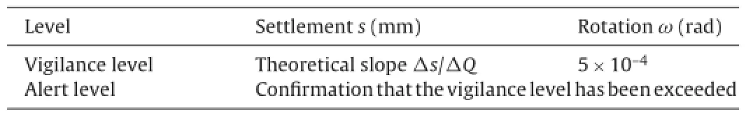
Table 2Definition of vigilance and alert levels.
Fig. 5 compares the actual settlement and rotation values recorded for piers P2 (foundation in limestone) and P6 (foundation in marls) in relation to time and concrete mass, with the theoretical values. It is noted that the settlement values recorded in the limestone show abrupt variations followed by progress in plateaus, whereas the settlement observed in the marl is more continuous. It seems likely that this is due to extensive natural fracturing in the limestone on one hand, and the disorganization of soil structure caused by the explosives used to excavate the pile shaft on the other. Furthermore, the slopes of the average settlement curves are generally below the vigilance level, bearing in mind the previous comment. The rotation values are very low and always well below the vigilance level, which is very important for the structure. It waschecked, by the yearly controls, that the foundations deformations did not change 8 years after their completion.

Fig. 5. Comparison of calculations and observations for the total settlements of the piers (a) P2 in limestone and (b) P6 in marls.
5. Conclusions
The findings of the studies and monitoring of the Millau vaduct foundations during pier construction are as follows:
(1) Despite its limitations, the RMR method which was originally developed for tunnelling in rock masses provides a fairly reliable assessment of the mechanical properties for the foundations on the limestone and compacted marl encountered on the site.
(2) The actual behaviour of the pier foundations proved to be that of a piled raft foundation in which the load carried by the footing increases with the stiffness of the soil on which it is laid, which is particularly relevant for piers with foundations in limestone.
(3) The foundation settlement and rotation values recorded during the construction and after completion are quite close to the results of the piled raft foundation calculation.
(4) The settlement observed as the piers went up varied according to the type of ground. Although it was fairly continuous in the marl, it showed abrupt increases in the limestone, which then continued in plateaus.
(5) The observational method has been proved to be a sound tool for monitoring the risk of movement in the pier foundations, given the possibility of discovering unidentified karsts or zones of heterogeneity.
(6) Overall settlement of the piers under their own weight does not exceed 5 mm. The rotations are minimal and can barely be measured. This means that the thresholds used for the implementation of the observational method have not yet been reached.
Allagnat D. La méthode observationnelle pour le dimensionnement interactif des ouvrages. Paris: Presses de l’Ecole Nat. des Ponts et Chaussées, Mai; 2005 (in French).
Bieniawski ZT. Engineering rock mass classifications. New York: Wiley; 1989.
Duncan CW. Foundations on rock. London: E & FN Spon/Chapman & Hall; 1996.
Frank R, Zhao SR. Estimation par les paramètres pressiométriques de l’enfoncement sous charge axiale des pieux forés. Bull. Liaison LCPC No. 119; 1982.
Hoek E, Brown ET. The Hoek-Brown failure criterion – a 1988 update. In: Curran JH, editor. Proc. 15th Canadian Rock Mech. Symp. Toronto: Department of Civil Engineering, University of Toronto; 1988. p. 31–8.
Hoek E, Brown ET. Underground excavations in rock. London: E & FN Spon/Chapman & Hall; 1996.
Hoek E, Kaiser PK, Bawden WF. Support underground: excavations in hard rock. Rotterdam: A.A. Balkema; 1995.
Mennessier G, Collomb P. Carte géologique de Millau et sa notice géologique. Orléans Cedex: BRGM; 1983.
Panet M. La mécanique des roches appliquée aux ouvrages de génie civil. Nationale des Ponts et Chaussées: association amicale des ingénieurs anciens élèves de l’Ecole Nationale des Ponts et Chaussées; 1976 (in French).
Peck RD. Advantages and limitation of the observational method in applied soil mechanics. Geotechnique 1969;19(2):171–87.
Peck RD. The observational method can be simple. Proceedings of the ICE Geotechnical Engineering 2002;149(2):71–4.
Yu Xianbin, Vayssade B. Joint profiles and their roughness parameters. International Journal of Rock Mechanics and Mining Sciences 1991;28(4): 333–6.
∗Corresponding author.
E-mail address: schlosserfr@wanadoo.fr (F. Schlosser).
Peer review under responsibility ofinstitute of Rock and Soil Mechanics, Chinese Academy of Sciences.
1674-7755 © 2013 Institute of Rock and Soil Mechanics, Chinese Academy of Sciences. Production and hosting by Elsevier B.V. All rights reserved.
http://dx.doi.org/10.1016/j.jrmge.2013.05.002
 Journal of Rock Mechanics and Geotechnical Engineering2013年3期
- Journal of Rock Mechanics and Geotechnical Engineering的其它文章
- On the chemo-thermo-hydro-mechanical behaviour of geological and engineered barriers
- On the thermal impact on the excavation damaged zone around deep radioactive waste disposal
- Homogenization in clay barriers and seals: Two case studies
- Joints in unsaturated rocks: Thermo-hydro-mechanical formulation and constitutive behaviour
- Sealing of fractures in claystone
- Short- and long-term behaviors of drifts in the Callovo-Oxfordian claystone at the Meuse/Haute-Marne Underground Research Laboratory