
Homogenization in clay barriers and seals: Two case studies
2013-06-05 14:54:26GensVllejZndrnchezDeprtmentofGeotechniclEngineeringndGeosciencesUniversittPolitcnicdeCtlunyBrcelonSpin
A. Gens, B. Vlleján, M.T. Zndrín, M. SánchezDeprtment of Geotechnicl Engineering nd Geosciences, Universitt Politècnic de Ctluny, Brcelon, Spin
bZachry Department of Civil Engineering, Texas A&M University, College Station, TX, USA
Homogenization in clay barriers and seals: Two case studies
A. Gensa,∗, B. Vallejána, M.T. Zandarína, M. Sánchezb
aDepartment of Geotechnical Engineering and Geosciences, Universitat Politècnica de Catalunya, Barcelona, Spain
bZachry Department of Civil Engineering, Texas A&M University, College Station, TX, USA
ARTICLE INFO
Article history:
Received 26 March 2013
Received in revised form 10 April 2013
Accepted 25 April 2013
Nuclear waste disposal
Clay barriers
Clay seals
Heterogeneity
Compacted soils
Coupled analyses
Unsaturated soils
The paper presents two case studies that provide information on the process of homogenization ofinitially heterogeneous clay barriers and seals. The first case is the canister retrieval test performed in the Aspö Hard Rock Laboratory (Sweden). The heterogeneity arises from the use of a combination of blocks and pellets to construct the engineered barrier. The degree of homogenization achieved by the end of the tests is evaluated from data obtained during the dismantling of the test. To assist in the interpretation of the test, a fully coupled thermo-hydro-mechanical (THM) analysis has been carried out. The second case involves the shaft sealing test performed in the HADES underground research laboratory (URL) in Mol (Belgium). Here the seal is made up of a heterogeneous mixture of bentonite pellets and bentonite powders. In addition to the full scale test, the process of homogenization of the mixture has also been observed in the laboratory using X-ray tomography. Both field test and laboratory tests are successfully modelled by a coupled hydro-mechanical (HM) analysis using a double structure constitutive law. The paper concludes with some considerations on the capability of highly expansive materials to provide a significant degree of homogenization upon hydration.
© 2013 Institute of Rock and Soil Mechanics, Chinese Academy of Sciences. Production and hosting by Elsevier B.V. All rights reserved.
1. Introduction
In many designs of high level nuclear waste disposal schemes in deep geological repositories, the canister containing the waste is surrounded by a clay-based engineered barrier. The barrier is usually composed of compacted clay with high swelling characteristics, sometimes it is mixed with other materials such as sand or excavation products. In the initial transient period, the barrier is subjected to considerable thermo-hydro-mechanical (THM) actions that may bring about important changes to the final state of the barrier (Gens et al., 2002; Gens, 2010). Other important elements in deep geological repositories are the seals required for access shafts and drifts that are also constructed, in most cases, using clayey materials. Seals are also subjected to substantial hydro-mechanical (HM) effects in the initial transient period.In both barriers and seals, chemical actions are also significant but they are outside the scope of this paper (Guimarães et al., 2007).
The desired outcome is that, at the end of this THM-influenced transient phase, the engineered clay barrier or the seal is in a state as uniform as possible in order that there are no preferential paths for radionuclide migration. However, the initial state of the barrier after emplacement is often quite different from homogeneity. Some barriers are made up of compacted bentonite blocks that leave between them initially open joints (Gens et al., 2009). Heterogeneities also arise from the lack of perfect contact between blocks and the surface of the opening in which they are emplaced. In other cases, barriers or seals are made up of a combination of pellets and powder so the heterogeneity is intrinsic to the material used throughout (Volckaert et al., 2000). Significant initial heterogeneity is also a feature in the designs that use a combination of compacted clay blocks and pellets in order to take advantage of the favourable properties of each type of materials (Thorsager et al., 2002). In all these situations, it is important to try to ascertain, as accurately as possible, the final state of the barrier or seal with respect to the degree of homogeneity. This goal can best be achieved by a combination of experiments and numerical analyses conveniently validated against the observations of those same tests.
In this paper, two case studies are presented and discussed focusing on the issue of barrier/seal homogenization. The first one is a THM in situ test where the engineered barrier is made up of bentonite blocks with an annulus of pellets placed between blocks and borehole wall. The second one refers to in situ and laboratory seal experiments where the material is an initially heterogeneousmixture of bentonite pellets and bentonite powder. Some general concluding remarks, based on the cases described, close the paper.

Fig. 1. Layout of the canister retrieval test (unit: mm).
2. The canister retrieval test
2.1. Description and experimental protocol
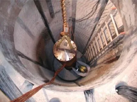
Fig. 2. Installation of the canister retrieval test.
The canister retrieval test, CRT (Thorsager et al., 2002), is a fullscale in situ heating test that involves the placement of a full-scale canister in a vertical borehole surrounded by an engineered barrier. The layout of the test is depicted in Fig. 1 and a picture of the installation is presented in Fig. 2. The test is located in the 420 m level of the Aspö Hard Rock Laboratory (Sweden) excavated in granite. The borehole was bored with a full-face tunnel boring machine modified for vertical. The deposition borehole is 8.55 m deep and has a diameter of 1.76 m. The surrounding rock at the upper part of the borehole consists mainly of greenstone and at the lower part of Äspö diorite. For the purpose of applying arti ficial hydration to the barrier, 16 filter mats with a width of 10 cm were installed adjacent to the rock wall with uniform spacing, starting 0.15 m from the borehole bottom up to a 6.25 m height.
MX-80 bentonite was used to construct the engineered barrier. The barrier consists of highly compacted bentonite blocks with an initial dry density of 1710–1790 kg/m3. The initial water content of the bentonite was 17.3–16.7% with a mean value of 17%. The bentonite buffer was installed in the form of cylindrical or ring blocks, depending on elevation. The blocks have a diameter of 1.65 m and a height of 0.5 m. When the stack of blocks was 6 m high, the canister, equipped with electrical heaters, was lowered down in the centre of the borehole and the cables to the heaters and instruments were connected. A canister obtained from SKB’s encapsulation project was used in this test. The outside diameter of the canister is 1.05 m. The height of the canister is 4.83 m and the weight is 21.4 tonnes.
At the top of the canister, MX-80 bentonite bricks fill up the volume between the canister top surface and the top surface of the upper ring (R10). The height difference between the two surfaces was 220–230 mm. More importantly for our purposes, the space between bentonite blocks and the borehole wall was filled with bentonite pellets and water. Additional blocks were emplaced until the borehole was filled to a distance of 1 m from the tunnel floor.
The top of the borehole was sealed with a retaining structure formed by a plug made of concrete, a steel lid and rock anchors. The aim of the structure was to prevent the blocks of bentonite from swelling uncontrollably. An impermeable rubber mat was installed between the top bentonite block C4 and the concrete plug. On top of the plug, a steel lid was installed. The plug and lid can move vertically and are attached to the rock by 9 rock anchors made up of 19 steel wires having 5 m fixed length and 5 m free length. The inclination of the anchors is 2.5:1.
A large number ofinstruments were installed to measure the following variables:
(1) Canister: temperature and strain;
(2) Rock mass: temperature and stress;
(3) Retaining system: force and displacement;
(4) Buffer: temperature, relative humidity, pore pressure and total pressure.
The protocol can be readily summarized in the following points:
(1) The starting date of the test was October 26, 2000 when the buffer-rock interface was filled with pellets. Afterwards, water was pumped into the gap occupied by the pellets and the filter mats.
(2) Once pellets were hydrated, the concrete plug was cast and heating started. Heating began with an initially applied constant power of 700 W at day 1.
(3) When the concrete plug rose 13 mm due to bentonite swelling, three rock anchors were locked on day 5. The initial force in each anchor was 20 kN.
(4) The canister heating power was raised twice, at day 18 to 1700 W and at day 110 to 2600 W, respectively.
(5) When the total force exceeded 1500 kN, the remaining 6 anchors were fixed. This procedure took place at days 46–48. The total force, distributed equally among all anchors, is about 170 kN per anchor.
(6) The water pressure at filter mats was increased gradually up to 0.8 MPa from day 679 to day 714 (September 5, 2002 to October10, 2002). At day 770, the water pressure was decreased to 0.1 MPa. Then it was increased again up to 0.8 MPa at day 819 and remained constant until day 1598 when the water pressure was removed.
(7) The heating was switched-off at day 1811.
After the end of test, several samples from the buffer were obtained by drilling to determine their dry density and degree of saturation.
2.2. Observations and analysis
A fully coupled THM analysis of the test was performed to aid in the interpretation of the results. A full description of the numerical model, constitutive laws and material parameters is given in Zandarín et al. (2011). Here, only the mechanical constitutive law that controls the subsequent homogenization of the barrier materials is briefly considered. For this particular case, the same constitutive law was used for the bentonite blocks and the pellets, namely a modified form of the Barcelona basic model (BBM) first described in Alonso et al. (1990). Although block and pellets appear as quite different materials, it was judged sufficient to use the same constitutive law although, naturally, with quite different material parameters and initial void ratios. However, it is well known that the BBM is not appropriate for describing the mechanical behaviour of highly swelling clays; consequently, the original elastic formulation (i.e. that applying inside the main yield surface) was modified to account for the expansive behaviour of the bentonite. Elastic behaviour was defined by
The elastic stiffness for net mean stress depends on suction as

where κi0is the elastic stiffness in saturated conditions and αiis a model parameter.
The elastic stiffness for suction depends on net mean stress as

where κs0and αspare model parameters, and prefis a reference pressure.
Although the overall modelling is not the main focus of the paper, Figs. 3 and 4 are presented to illustrate the quite reasonable reproduction of the test results by the numerical modelling performed.
2.3. Homogenization observations
From the point of view of examining the degree of homogenization achieved in the barrier, the most relevant data come from the dismantling of the test. After the end of the test, samples at selected sections of C3, R10 and R6 (Fig. 1) were cored from both the bentonite and pellets zones. The dry density and water content of samples were measured in the laboratory and the corresponding degree of saturation was calculated. The results are shown in Figs. 5–7. The corresponding initial values and model computations are also shown in the same figures.
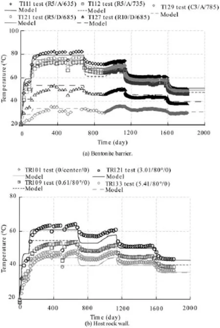
Fig. 3. Evolution of temperatures in the engineered barrier and in the host rock.
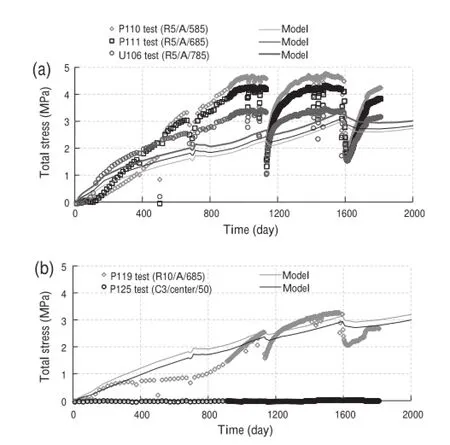
Fig. 4. Evolution of total stress in the engineered barrier.
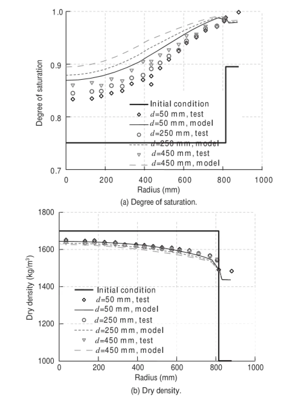
Fig. 5. Final distributions of degree of saturation and dry density of C3.
It can be noted that the final degree of saturation throughout the bentonite barrier is significantly higher than the initial one even in the zones close to the canister where heating and initial evaporation have been strong. It is evident that natural and, especially, artificial hydrations have dominated the behaviour of the barrier. Naturally, the degree of saturations is higher in the zone close to the rock boundary from which water entry was taking place.
From the point of view of homogenization, the observations are especially interesting. In general, dry density has reduced in the blocks due to the expansion of the material related to hydration. Naturally, being a nearly closed system, block expansion has been compensated by compression of the pellet-filled slot close to the rock that has increased its dry density by a very significant amount. As a consequence, a significant homogenization of the barrier has taken place, although some moderate differences still remain. Since hydration was not complete at the end of the test, it is easy to anticipate that homogenization would still be greater on the barrier reaching full saturation.
It is also noteworthy that the rather simple constitutive model employed is capable of achieving a very satisfactory reproduction of the observations.
3. The shaft sealing test
3.1. Description of the test
The shaft sealing test (Volckaert et al., 2000) has been performed in the HADES underground research laboratory (URL) located in Mol (Belgium). The host material is Boom Clay, an overconsolidated plastic clay of Rupelian Age. The sealing test has been performed in an experimental shaft located at the end of the main test drift (Fig. 8). To this end, the bottom part of the shaft was filled with grout and the concrete lining was removed at the location of the seal. The sealed section is about 2.2 m in diameter and 2.25 m in height. The sealing material is a mixture of 50% of powder and 50% of highly compacted pellets of FoCa Clay.
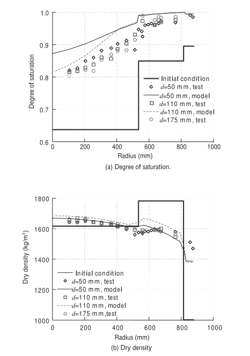
Fig. 6. Final distributions of degree of saturation and dry density of R10.
The seal was kept in place with a top concrete lid about 1 m thick. A large number of sensors measuring pore water pressure, total stress, displacement and relative humidity were installed to follow the HM evolution of the seal and the surrounding host rock. In the seal, most instruments are located on 6 rods of stainless steel connected to a central tube. Those rods are located in 2 groups of 3 rods each at two levels: the instrumented level top (ILT) and the instrumented level bottom (ILB). The ILT is located at 180 cm and the ILB at 65 cm from the bottom of the plug. Some instrumentation is also located at the hydration level top (HLT) and at the hydration level bottom (HLB). The instrumented sections are indicated in Fig. 9. Several filters inside the sealed section enabled additional artificial hydration to be performed in order to reduce the time required to attain saturation.
After coating the concrete plug with a resin, the clay mixture was installed using approximately 12 tonnes of powder/pellets mixture. The first 60 cm were compacted with a vibro-compactor specially designed for the project. After compaction, the mixture had a dry density of 1.54 g/cm3. The rest of the mixture of powder and pellets was not compacted in order to avoid damage of the sensors, resulting in a dry density of 1.39 g/cm3. A top view of the shaft during backfill installation has been provided in Fig. 10.
After backfilling the shaft and closing the concrete seal, a 7-month period was allowed to elapse to achieve steady state conditions in the zone around the test. Afterwards, artificial hydration was applied during 6 years. Some leakage problems occurred in the early stages of the test and hydration had to be stopped and re-started on a few occasions. The water injection pressure wasincreased gradually up to a value of 300 kPa, approximately, measured at the elevation of the main drift. After seal saturation, various gas and liquid permeability tests have been performed but only the hydration stage is considered in this paper.

Fig. 7. Final distributions of degree of saturation and dry density of R6.
3.2. Observations and analysis
In this case, the test is performed under isothermal conditions, so only fully coupled HM analyses are required. Due to the presence of both powder and pellets, it appears that the adoption of a double porosity model is eminently suited to describe the heterogeneous nature of the material. The formulation presented in Sánchez (2004) has been adopted.
In this formulation, the overall medium is assumed to consist of two overlapping but distinct continua. The macrostructure refers to the large scale arrangement of soil particle aggregates and the relatively large pores between them. It is expected that, initially, most of the macrostructural pores belong to the bentonite powder. The microstructure refers to the clay particles and the micropores and interparticle spaces associated with them. A large proportion of the micropores lie initially in the high-density pellets but there will also be micropores in the clay particle aggregates present in the powder. Ideally, the microporosity of the powder aggregates should be distinguished from that in the pellets but, in that case, the number ofinteractions and parameters multiply, leading to a cumbersome formulation difficult to apply in practice. In the following, subscript “M” will stand for the macrostructure and subscript “m”for the microstructure. Accordingly, macroporosity and microporosity are denoted as φMand φm, respectively. Macroporosityand microporosity are defined as the volume of macropores and micropores, respectively, divided by the total volume of the soil. Thus, total porosity equals φM+ φm. The degree of saturation of the macroporosity, SwM, is the volume of macropores occupied by water over the volume of the macropores; an equivalent definition holds for the microporosity degree of saturation, Swm.
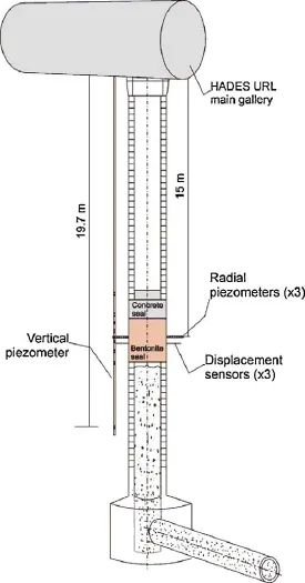
Fig. 8. Schematic view of the shaft sealing test.
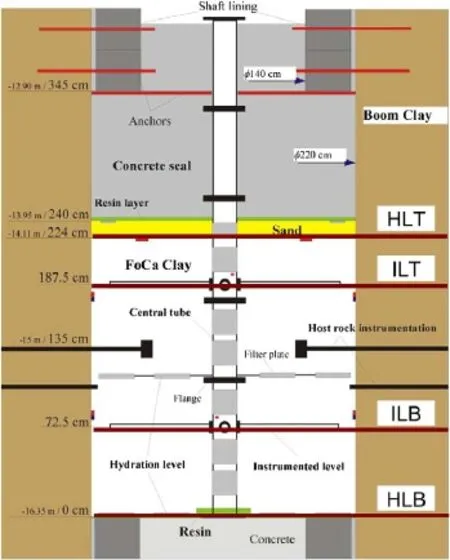
Fig. 9. Layout of the test showing instrumentation and artificial hydration levels.

Fig. 10. Shaft backfill with a mixture of bentonite pellets and bentonite powder.
An important feature is that hydraulic equilibrium between the two continua is not assumed, i.e. at each point of the domain the water potentials in the two continua may be different, leading to an exchange of water between them. For simplicity, a linear relationship is assumed (e.g. Wilson and Aifantis, 1982) where water exchange is described by

where Γwis the water exchange term, γ is a parameter (often called the leakage parameter), and ψ is the total water potential. It is assumed that only matric and gravitational potential contribute to the total potential of the macrostructure but an additional osmotic component may also contribute to the microstructural potential (Gens, 2010). Water exchange will therefore be driven by suction differences. Naturally, two water balance questions (one for the macrostructure and a second one for the microstructure) are considered in the formulation.
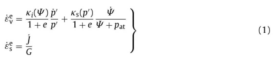
In accordance with the double porosity assumption, a double structure approach is adopted for the mechanical constitutive law (Gens and Alonso, 1992). Here, the mathematical model is formulated in terms of generalized plasticity (Sánchez et al., 2005). The model assumes that the physico-chemical phenomena occurring at the microstructural level are basically reversible and largely volumetric. Then the deformations arising from microstructural phenomena can be obtained from a nonlinear elastic model dependent on a microstructural mean stress defined as
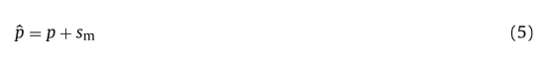
where p is the net mean stress and smis the microstructural suction.
In a p–s plane, the line corresponding to constant microstructural mean stresses is referred to as the neutral line, since no microstructural deformation occurs when the stress path moves on it. The neutral loading line divides the p–s plane into two parts, defining two main microstructural stress paths: a microstructural contraction (MC) path when the microstructural mean stress increases and a microstructural swelling (MS) path when the microstructural mean stress reduces.

Fig. 11. Variation of suction with time at instrumentation level top.
The increment of the microstructural elastic deformation is expressed as a function of the increment of the microstructural mean stress:

where εvmis the microstructural volumetric strain increment, Kmis the microstructural bulk modulus, emis the microstructural void ratio, and κmis a model parameter. The behaviour of the macrostructural level is defined by the BBM (Alonso et al., 1990) where the main yield surface is denoted by LC (loading-collapse).
A fundamental assumption of the framework is that the microstructural behaviour is not affected by the macrostructure state but it only responds to changes in the driving variables (i.e. stresses and suction) at local microstructural level. In contrast, plastic macrostructural strains may result from deformations of the microstructure. It is postulated that plastic macrostructural strains can be expressed as

The hydration of the seal has been simulated using the theoretical framework briefly outlined in this section and has been reported in detail in Gens et al. (2011). For brevity, only two examples of the test observations and computed results are included here. Fig. 11 shows the variation over time of the suction measured in the relative humidity sensors located on the rods of the ILT, the instrumentation level located in the uncompacted part of the backfill. There are only two sensors because the one oriented towards the west failed from the start. The sensor closer to the rock (RH-S-ILT-E) appeared to hydrate only a little faster than the one placed near the centre (RH-S-ILT-N), suggesting that natural hydration from the host Boom Clay is not dominant. The computed suction evolutions are quite close to observations in this case and the analysis also shows a somewhat faster hydration in the sensor closer to the rock boundary.
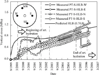
Fig. 12. Variation of vertical total with time at hydration level bottom.
The evolution of vertical stresses at four points located at the hydration level bottom (HLB) of the seal is shown in Fig. 12 and compared with the results of the analysis. The usual difficulties associated with trying to measure stresses precisely are apparent in the plots. It can also be noted that stress development is not quite axisymmetric. The response of the sensors does not appear to be simultaneous with hydration; this may be perhaps attributed in part to a lack of close contact with the backfill after installation. In spite of those difficulties, the analysis appears to give correctly the rough magnitude of the hydration swelling pressure as well as the rate of stress increase in the later stages of the test.
Unfortunately, in this case there was no systematic dismantling of the test; thus no direct observations concerning the degree of homogenization are available. For this, it is necessary to resort to laboratory tests as discussed in the next section.
3.3. Homogenization observations
Interactions in the microfabric of the material must underlie its behaviour during hydration. Direct observations of the hydration process were obtained by Van Geet et al. (2005) using microfocus X-ray computed tomography. A 50/50 powder–pellets mixture of FoCa Clay at a dry density of 1.36 g/cm3and an average water content of 5.67% was placed in a plexiglas cylindrical cell. The sample was 7 cm high and 3.8 cm in diameter. Hydration was performed from the bottom of the sample under constant volume conditions. During the first 1.5 months, water was supplied at a very low pressure; afterwards, water was injected at a pressure of 0.5 MPa during 4 additional months.
X-ray tomography observations could be performed at specified time intervals. From the computation of the linear X-ray attenuation coefficient, the density distribution throughout the sample could be determined. Fig. 13 shows the density distribution on a vertical slice through the centre of the sample at different times of the test. It can be noted that at the initial state there is a clear difference in density between pellets and powder and that during hydration. The density of the pellets reduces (swelling) whereas the density of the powder rises because of both soil compression and water content increase. The changes move gradually from bottom to top following the progress of hydration. However, the most interesting information is that, at the end of the test, the fully hydrated sample appears to be totally homogenous.

Fig. 13. Distribution of densities on a vertical slice through the centre of the sample observed at different stages of hydration (Van Geet et al., 2005).
The behaviour of the powder–pellets mixture during hydration has been examined by means of laboratory swelling pressure tests (Imbert and Villar, 2006). Note that the hydration of a shaft or tunnel seal due to the inflow of host rock water is akin to a swelling pressure test due to the confinement provided by the excavation walls. Swelling pressure tests are, therefore, very appropriate to examine the behaviour relevant to seal hydration. The double porosity formulation and double structure constitutive model can now be used to gain further understanding of the homogenization process through the reproduction of the laboratory test results. Only two examples are shown in this paper.
Fig. 14 shows the characteristic development of swelling pressure during hydration of a pellets–powder mixture sample compacted to a dry density of 1.6 g/cm3. It can be noted that the swelling pressure increases rapidly at the beginning of the test, until reaching a peak value. Afterwards, the measure pressure drops to a minimum value to start later a new increase until reaching the stationary swelling pressure at the end of the test. This complex behaviour is the consequence of the interplay between macrostructure and microstructure. The initial swelling of the microstructure causes a collapse of the macrostructure but,at the later stages of the test, the expansion of the microstructure becomes dominant and controls the final swelling pressure.
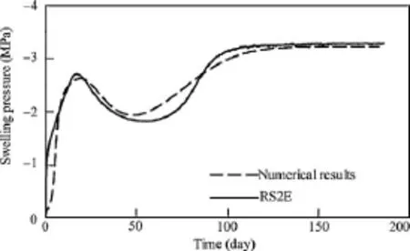
Fig. 14. Development of swelling pressure during the hydration of a pellets–powder sample with dry density 1.6 g/cm3. Model results and observed values in test RS2E.

Fig. 15. Computed macrostructure and microstructure specific volume during the hydration of a pellets–powder sample with dry density 1.6 g/cm3.
It is interesting to note that the double porosity formulation that incorporates explicitly this structural interplay is capable of reproducing faithfully the experimental results. In that case, it is worth exploring the numerical results to gain further insights into the underlying phenomena. Fig. 15 presents the computed evolution of macrostructure and microstructure specific volume at three different points of the specimen. In Fig. 15, yMand ymare the coordinates for the curves of macrostructure and microstructure specific volume evolution curves, respectively. The expansion of the microstructure and the reduction of the macroporosity are readily apparent. Very interestingly, the numerical model predicts a uniform sample at the end of hydration, consistent with the experimental observations above.
Exactly the same observations can be made concerning a test on a looser sample, compacted to a dry density of 1.45 g/cm3(Figs. 16 and 17) although, in this case, the final swelling pressure is, naturally, significantly lower.
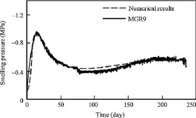
Fig. 16. Development of swelling pressure during the hydration of a pellets–powder sample with dry density 1.45 g/cm3. Model results and observed values in test MGR9.
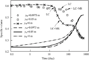
Fig. 17. Computed macrostructure and microstructure specific volume during the hydration of a pellets–powder mixture sample with dry density 1.45 g/cm3.
4. Concluding remarks
The issue of homogenization in clay barriers and seals has been examined with reference to two case studies. The first one is the canister retrieval test where an engineered barrier is subjected simultaneously to thermal action and to artificial hydration. At the end of the test, it is found that a significant degree of homogenization has been achieved between the heavily compacted bentonite rings and cylinders that constitute the buffer and the ring of pellets that fill the annular space between blocks and borehole wall. Hydration is not complete at the end of the test so, probably, a full hydration would result in still high degree of uniformity. A fully coupled THM analysis has been performed in which the mechanical behaviour of the materials involved is represented by a single structure model. The test observations are satisfactorily reproduced by the numerical analysis, including a good estimate of the homogenization process.
The second case is the shaft sealing test, a large scale test in which the seal is constituted by a mixture of bentonite pellets and bentonite powder. The special characteristics of the material suggest the use of a double porosity formulation coupled to a double structure constitutive model. There is no thermal action in this case, so the coupled analysis is performed under isothermal conditions. In this case, homogenization evidence is best obtained from parallel laboratory tests. In particular, use of X-ray tomography indicated that the sample is practically homogeneous at the end of the test when the specimen is fully hydrated. Again, the numerical model allows a close simulation of the experimental results including the fact that a uniform sample is obtained at the end of the test.
It is therefore apparent that the use of highly expansive clays for barriers and seals leads, at least in the two cases examined, to progressively homogenous materials. The capability of the numerical models to reproduce experimental observations should also be remarked.
Acknowledgements
The work reported has been co-funded by ANDRA, CIEMAT, ONDRAF-NIRAS and the European Commission (EC contracts FIKWCT-2000-00010 and STRP-036458). The support of the Spanish Ministry of Science and Innovation trough grant BIA2011-27217 is also gratefully acknowledged.
Alonso EE, Gens A, Josa A. A constitutive model for partially saturated soils. Géotechnique 1990;40(3):405–30.
Gens A. Soil–environment interactions in geotechnical engineering. 47th Rankine Lecture. Géotechnique 2010;60(1):3–74.
Gens A, Alonso EE. A framework for the behaviour of unsaturated expansive clays. Canadian Geotechnical Journal 1992;29(6):1013–32.
Gens A, Guimarães Ldo N, Garcia-Molina A, Alonso EE. Factors controlling rock–clay buffer interaction in a radioactive waste repository. Engineering Geology 2002;64(2):297–308.
Gens A, Sánchez M, Guimarães Ldo N, Alonso EE, Lloret A, Olivella S, et al. A full-scale in situ heating test for high-level nuclear waste disposal: observations, analysis and interpretation. Géotechnique 2009;59(4):377–99.
Gens A, Valleján B, Sánchez M, Imbert C, Villar MV, Van Geet M. Hydromechanical behaviour of a heterogeneous compacted soil: experimental observations and modelling. Géotechnique 2011;61(5):367–86.
Guimarães Ldo N, Gens A, Olivella S. Coupled thermo-hydro-mechanical and chemical analysis of expansive clay subject to heating and hydration. Transport in Porous Media 2007;66(3):341–72.
Imbert V, Villar MV. Hydro-mechanical response of a bentonite pellets/powder mixture upon infiltration. Applied Clay Science 2006;32(3/4):197–209.
Sánchez M. Thermo-hydro-mechanical coupled analysis in low permeability media. Barcelona, Spain: Universitat Politecnica de Catalunya; 2004 (PhD Thesis).
Sánchez M, Gens A, Guimarães Ldo N, Olivella S. A double structure generalized plasticity model for expansive materials. International Journal for Numerical and Analytical Methods in Geomechanics 2005;29(8):751–87.
Thorsager P, Börgesson L, Johannesson LE, Sandén T. Canister retrieval test, Report on installation, International progress report 02-30; 2002.
Van Geet M, Volckaert G, Roels S. The use of microfocus X-ray computed tomography in characterising the hydration of a clay pellet/powder mixture. Applied Clay Science 2005;29(2):73–87.
Volckaert G, Dereeper B, Put M, Ortiz L, Gens A, Vaunat J, et al. A largescale in situ demonstration test for repository sealing in an argillaceous host rock RESEAL project—Phase I. Luxembourg: European Commission; 2000, EUR 19612.
Wilson R, Aifantis E. On the theory of consolidation with double porosity. International Journal of Engineering Science 1982;20(9):1019–35.
Zandarín MT, Gens A, Olivella S, Alonso EE. Thermo-hydro-mechanical model of the canister retrieval test. Physics and Chemistry of the Earth 2011;36(17/18):1806–16.

Antonio Gens obtained a M.Sc. and a Ph.D. degree from Imperial College, London. He is a professor of Geotechnical Engineering at the Technical University of Catalonia in Barcelona where he has been Head of the Department of Geotechnical Engineering and Geosciences and member of the Governing Council of the University. He has been involved in geotechnical research, consulting and education for more than 30 years. He is the author or co-author of more than 250 scientific papers and he sits in the Editorial Board of several International Journals. He is a core member of TC105 (unsaturated soils) and TC215 (environmental geotechnics) of the ISSMGE. He has consulted widely and has given geotechnical advice on a series of landmark projects, both at home and abroad. In recent years, he has been awarded the Case History Award by the American Rock Mechanics Association in 2006, the R.M. Quigley Award by the Canadian Geotechnical Society in 2009 and the Outstanding Contributions Award by the International Association for Computer Methods and Advances in Geomechanics (IACMAG) in 2011. Also, the UK Institution of Civil Engineers has awarded him the Telford Medal twice (in 1994 and 2007) and the George Stephenson Medal also twice (in 2008 and 2012). In 2007, he delivered the 47th Rankine Lecture. He is a member of the Royal Academy of Doctors of Spain and in 2011 he became a Fellow of the UK Royal Academy of Engineering. He has recently been elected Vice-President for Europe of the ISSMGE for the period 2013–2017.
∗Corresponding author. Tel.: +34 934016867.
E-mail address: antonio.gens@upc.edu (A. Gens).
Peer review under responsibility ofinstitute of Rock and Soil Mechanics, Chinese Academy of Sciences.
1674-7755 © 2013 Institute of Rock and Soil Mechanics, Chinese Academy of Sciences. Production and hosting by Elsevier B.V. All rights reserved.
http://dx.doi.org/10.1016/j.jrmge.2013.04.003
 Journal of Rock Mechanics and Geotechnical Engineering2013年3期
- Journal of Rock Mechanics and Geotechnical Engineering的其它文章
- Millau viaduct geotechnical studies and foundations
- TIMODAZ: A successful international cooperation project to investigate the thermal impact on the EDZ around a radioactive waste disposal in clay host rocks
- Short- and long-term behaviors of drifts in the Callovo-Oxfordian claystone at the Meuse/Haute-Marne Underground Research Laboratory
- Sealing of fractures in claystone
- Joints in unsaturated rocks: Thermo-hydro-mechanical formulation and constitutive behaviour
- On the thermal impact on the excavation damaged zone around deep radioactive waste disposal