On the chemo-thermo-hydro-mechanical behaviour of geological and engineered barriers
Yu-Jun Cui, Anh Minh Tang
Laboratoire Navier/CERMES, Ecole des Ponts ParisTech, 6 et 8, Avenue Blaise Pascal, 77455 Marne-la-Vallée cedex 2, France
On the chemo-thermo-hydro-mechanical behaviour of geological and engineered barriers
Yu-Jun Cui∗, Anh Minh Tang
Laboratoire Navier/CERMES, Ecole des Ponts ParisTech, 6 et 8, Avenue Blaise Pascal, 77455 Marne-la-Vallée cedex 2, France
ARTICLE INFO
Article history:
Received 26 March 2013
Received in revised form 10 April 2013
Accepted 25 April 2013
Boom Clay (BC)
Bentonite-based materials
Mechanical behaviour
Hydraulic conductivity
Pore-water salinity
Technological voids
An overview of the recent findings about the chemo-hydro-mechanical behaviour of materials used for both geological and engineered barriers in nuclear waste disposal is presented, through some examples about the natural Boom Clay (BC) and compacted bentonite-based materials. For the natural BC, it was found that compression index identified from both oedometer and isotropic compression tests is similar and the compressibility of BC from the Mol site is higher than that of BC from the Essen site; the shear strength of Mol BC is also higher than that of the Essen BC, suggesting a significant effect of carbonates content; the thermal volume change is strongly overconsolidation ratio (OCR) dependent—low OCR values promote thermal contraction while high OCR values favour thermal dilation; the volume change behaviour is also strongly time dependent and this time dependent behaviour is governed by the stress level and temperature; the effect of pore-water salinity on the volume change behaviour can be significant when the smectite content is relatively high. For the bentonite-based materials, it was found that thermal contraction also occurs at low OCR values, but this is suction dependent—suction promotes thermal dilation. Under constant volume conditions, wetting results in a decrease of hydraulic conductivity, followed by an increase. This is found to be related to changes in macro-pores size—wetting induces a decrease of macro-pores size, followed by an increase due to the aggregates fissuring. The presence of technological voids can increase the hydraulic conductivity but does not in fluence the swelling pressure.
© 2013 Institute of Rock and Soil Mechanics, Chinese Academy of Sciences. Production and hosting by Elsevier B.V. All rights reserved.
1. Introduction
In the high-level radioactive waste geological disposal, multibarrier concept with geological barrier and engineered barrier is usually considered. The geological barrier is the natural host formation such as claystones (France and Switzerland), salts (Germany), granite (China and Sweden) and stiff clays (Belgium). The main functions of geological barrier are its low hydraulic conductivity and its capacity of self healing. The engineered barrier is made upof compacted bentonite-based materials. It is usually used with granite geological barriers (China and Sweden) and constitutes a barrier before the geological one. Note that these materials are also used as filling materials for other geological barriers. The main functions of the bentonite-based materials are their sealing capacity related to their volume change behaviour, swelling property, retention capacity and hydraulic behaviour.
In the situation of nuclear waste disposal, the constitutive materials of both barriers are subjected to complex coupled chemo-thermo-hydro-mechanical (CTHM) loadings stemming from interaction between clay minerals and pore-water chemistry or other chemicals resulted from concrete alteration, from heat emission of the waste canisters, from water flow and from field stress/materials swelling. This justifies the wide studies conducted on their CTHM behaviours in both laboratory and field conditions.
In field, tests have been performed in different Underground Research Laboratories (URLs). For instance, the French agency (ANDRA) has carried out various tests in the Bure URL to investigate the involved Oxfordian claystone behaviour during excavation, heating, etc. The Swiss agency (Nagra) has done the same in the Mont Terri URL. The Belgian agency (Ondraf/Euridice) has investigated the hydraulic behaviour and mechanical behaviour of Boom Clay (BC) in the Mol URL. Note also that the French institution IRSN(Institut de Radioprotection et de la Sûreté Nucléaire) has been conducting the infiltration tests aiming at identifying the key factors related to the long-term performance of bentonite-based sealing systems when considering the initial technological void. The thermal loading effect has been also investigated in different URLs, for instance, in the Mol URL, a 10-year heating project—Praclay project is underway, aiming at investigating the effect of heating on the hydro-mechanical of BC on one hand, and the sealing capacity of the compacted bentonite ring on the other hand.

Table 1Geotechnical properties of the soil cores studied.
In the laboratory, several studies on the hydro-mechanical behaviour of geological formations have been conducted (Horseman et al., 1987; Baldi et al., 1988, 1991; Sultan, 1997; Sultan et al., 2000, 2002; Coll, 2005; Deng et al., 2011a, 2011b, 2011c, 2012). A large number of studies have also been performed on the thermo-hydro-mechanical (THM) behaviour of bentonitebased materials (Pusch, 1979; Dixon et al., 1985, 1987, 1992, 1996, 1999; Yong et al., 1986; Delage et al., 1998, 2006; Lee et al., 1999; Romero et al., 1999, 2011; Börgesson et al., 2001; Cui et al., 2002, 2008, 2011; Marcial et al., 2002; Marcial, 2003; Montes et al., 2003; Villar and Lloret, 2004, 2008; ANDRA, 2005; Agus, 2005; Villar, 2005; Lloret and Villar, 2007; Agus and Schanz, 2008; Agus et al., 2010; Gatabin et al., 2008; Karnland et al., 2008; Komine et al., 2009; Ye et al., 2009; Komine, 2010; Komine and Watanabe, 2010; Tang and Cui, 2010a, 2010b; Wang et al., 2012).
In this paper, some advances on the CTHM behaviours of materials used for geological and engineered barriers are presented through some examples about the natural BC from both Mol site and Essen site in Belgium and compacted bentonite-based materials.
2. Volume change behaviour of Boom Clay
In the Belgian programme for nuclear waste disposal, BC has been investigated for both Mol site (URL location) and Essen site (about 50 km east from Mol). In order to compare its volume change behaviour for both sites, five cores (1 m long and 100 mm in diameter) were taken from the Essen site and one core was taken from the Mol site at a depth of 223 m. The geotechnical properties of these cores are shown in Table 1.
For the BC at Essen, two cores were taken from the Putte member (Ess75 and Ess83) and three cores from the Terhagen member (Ess96, Ess104 and Ess112). The geotechnical properties of these cores are similar: specific gravity, Gs= 2.64–2.68; liquid limit, wL= 62%–78%; plastic index, IP= 36–45. The void ratio (e0) ranges from 0.700 to 0.785. The carbonate content of core Ess104 (4.36%) is significantly higher than those of other cores (lower than 1%). Note that the carbonate content for Ess112 is also relatively high: 2.64%.
After Francois et al. (2009), the main parameters of the BC at Mol, e.g. Gs, wLand IPare similar to those of the BC at Essen. The void ratio ranges from 0.49 to 0.67, significantly lower than that of BC at Essen. These differences suggest that the BC at Mol is denser and more carbonated.
Table 2 depicts the mineralogical compositions of different cores. It is observed that BC at Essen contains more active mineralssuch as smectite, but the total amount of smectite and interstratified illite/smectite is similar.

Table 2Mineralogical composition of clay fraction (<2 μm).
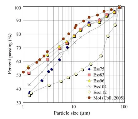
Fig. 1. Particle size distribution curves.
The particle size distribution curves are shown in Fig. 1. The curves of Ess83 and Ess96 are close to that of Mol, showing a clay content (<2 μm) of 57%–60%. The curves of Ess75 and Ess104 are slightly below the curves of Ess83, Ess96 and Mol, showing a content of clay-size particles of 43%–50%. Core Ess112 presents significantly larger particles and a lower value of clay content (about 40%).
Both oedometer and isotropic compression tests were carried out, allowing determination of the compression index Cc. The obtained values of Ccare shown in Table 3. It appears clearly thatboth tests give similar results. Comparison between the two sites shows that BC at Mol is more compressible than BC at Essen.

Table 3Compressibility parameters.
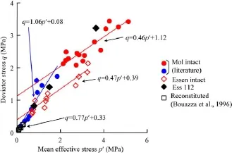
Fig. 2. Summary of failure envelopes of all Boom Clay considered Bouazza et al.,1996.
3. Shear strength of Boom Clay
In Fig. 2, the results at failure of BC at Mol by various authors (Horseman et al., 1987; Baldi et al., 1991; Van Impe, 1993; Sultan, 1997; Coll, 2005) and the results on BC at Essen are gathered in p'–q plane (mean effective stress-deviator stress plane) for a direct comparison. It appears clearly that the slope ofintact BC at Mol in the range of p'> 2 MPa and the slope ofintact BC at Essen is very close (0.46 against 0.47), suggesting a similar internal friction angle (12°–13°). However, the q0value (intersection) for Mol is significantly larger than that for Essen (1.12 MPa against 0.39 MPa). This corresponds to a higher effective cohesion for Mol as compared with that for Essen: 0.53 MPa against 0.19 MPa. This difference in cohesion is likely due to the difference in carbonate contents: BC at Mol has a higher content of carbonate (see Table 1).
The reconstituted Essen BC has an effective cohesion c'= 0.01 MPa and an internal friction angle φ'= 20°. These values are close to those of core Ess112.
4. Thermal volume changes
The overconsolidation ratio (OCR) is known to have a major effect on the volume change of soil heated under a constant load. At low OCR values, heating induces thermal contraction (Paaswell, 1967; Plum and Esrig, 1969). On the contrary, at high OCR values, heating results in thermal dilation (Baldi et al., 1988; Towhata et al., 1993).
This aspect was investigated for BC at various OCR values (OCR = 1, 2, and 12) by carrying out heating tests in a triaxial cell from 22°C to 100°C or tests with temperature cycles (22°C—100°C—22°C). The results are shown in Fig. 3. The OCR = 1 condition was achieved under confining stresses σ'c= 1.2 MPa and 3.85 MPa; the OCR = 2 condition was achieved under σ'c= 4 MPa and the OCR = 12 condition was achieved under σ'c= 4.2 MPa and 6 MPa, respectively.
The results of Fig. 3 confirm the four major trends of the thermal volume change behaviour of saturated clays:
(1) The thermal contraction of a normally consolidated sample is independent of the mean effective stress (see tests at OCR = 1 under 1.2 MPa and 3.85 MPa, and OCR = 12 under 4.2 MPa and 6 MPa). This trend was initially demonstrated by Demars and Charles (1982).

Fig. 3. Thermal volumetric changes of Boom Clay samples at different OCR values.
(2) The thermal contraction increases when OCR is decreased, leading to pure contraction at OCR = 1, in accordance with the results of Plum and Esrig (1969), Demars and Charles (1982) and Baldi et al. (1988).
(3) The slope of the volumetric strain in the cooling stage is independent of the applied mean effective stress.
(4) The temperature at which the transition between thermal expansion and contraction occurs decreases with OCR (T = 80°C at OCR = 12, T = 50°C at OCR = 2), in accordance with Baldi et al. (1988) and Towhata et al. (1993).
It is interesting to note that the slope of cooling is parallel to the slope of heating dilation. As physically the cooling process corresponds to a pure thermal contraction of the constituents of soil (solid and water), it can be considered as elastic. Thereby, the thermal contraction corresponds to a plastic process. Based on this consideration, Cui et al. (2000) developed a constitutive model allowing describing the thermo-mechanical behaviour of saturated clays.
5. Time dependent behaviour of Boom Clay
The time dependent behaviour of saturated BC was investigated in a triaxial cell under different isotropic stresses and at different temperatures (Cui et al., 2009). Fig. 4 presents the variation of consolidation rate from tests 7, 11, 13 and 15 as a function of temperature. A clear increase in consolidation rate with increasing temperature is observed. Furthermore, the relationship between the consolidation rate and time can be described by an exponential function. Note that this observation is made for a quite low stress range; experimental data for a larger stress range are needed to confirm this point.
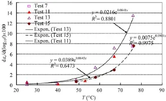
Fig. 4. Consolidation rate versus temperature for different heating tests on Boom Clay.

Fig. 5. Consolidation rate versus temperature for all tests performed on Boom Clay.

Table 4Pore-water salinity of Boom Clay.
Fig. 5 presents the variation of consolidation rate versus temperature for all the tests performed. The significant scatter observed is related to the influence of stress level, void ratio, thermal or mechanical loading rate, loading mode and loading interval. In spite of this, a clear trend showing an increase in consolidation rate with increasing temperature can be observed.
6. Effect of chemistry
Table 4 shows the chemical composition of pore-water of cores Ess83 and Ess96 (De Craen et al., 2006) and that of BC at Mol (Cui et al., 2009). The results show that the pore-water at Essen has NaCl as main salt, while the pore-water taken from Mol has NaHCO3as main salt. Comparison between the values for Ess83 and Ess96 shows that there is little difference between the two cores. The total salinity of the pore-water at Essen site is 5.037–5.578 g/L, while that at Mol site is only 1.286 g/L. The results also show that the main cation at both sites is Na+, with a concentration of 0.072–0.080 mol/L at Essen and 0.014 mol/L at Mol, i.e. 5–6 times lower. This difference in salinity shows the need ofinvestigating the effect of salinity on the hydro-mechanical behaviour of BC.
Oedometer tests were carried out for this purpose on cores Ess83 and Ess96 using two different pore-waters: synthetic water in tests Ess83Odo3 and Ess96Odo04; distilled water in tests Ess83Odo4 and Ess96Odo05. The compression curves obtained after saturating the soil samples with the corresponding pore-water were used to determine different parameters for each loading/unloading stage (see for instance Fig. 6a for test Ess83Odo3) such as the compression index (), the swelling index () and the oedometer modulus EOdothat is defined as where hiis the initial height of the soil sample and dh is the height change induced by a vertical stress increment.

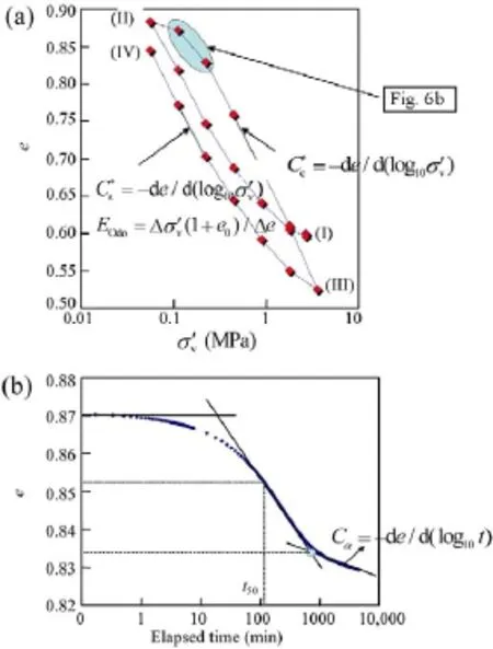
Fig. 6. Determination of parameters from the test Ess83Odo3.
In Fig. 6b, the void ratio change versus time is plotted for a loading step. This consolidation curve allows determination of the consolidation coefficient Cvfollowing the Casagrande’s method. Using the expression k = Cvρwg/EOdo, the hydraulic conductivity k can be calculated with ρwas the density of water and g as the gravitational acceleration.
Moreover, the curve shown in Fig. 6b can be used to determine the secondary deformation coefficient Cαthat corresponds to the slope of the line after the part of primary deformation. This definition implies that Cαis positive for loading stages as II→III, and negative for unloading stages as I→II and III→IV.
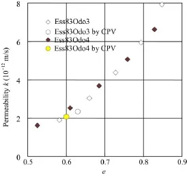
Fig. 7. Hydraulic conductivity versus void ratio for Ess83.

Fig. 8. Hydraulic conductivity versus void ratio for Ess96.
Figs. 7 and 8 show the hydraulic conductivity k versus void ratio e for the tests on Ess83 and Ess96, respectively. For each core, the results obtained with different water (synthetic water or distilled water) and by different methods (the direct method based on the water volume injected by the controller of pressure/volume (CPV) and the indirect Casagrande’s method) are gathered in a same figure for comparison. For Ess83, it can be observed that the measurements by the two methods gave similar results. On the other hand, the water chemistry did not affect the hydraulic conductivity since similar values were obtained with two different pore-water salinities. On the whole, a linear k–e relationship is observed. For Ess96, a little difference can be identified between test Ess96Odo4 with synthetic water and test Ess96Odo5 with distilled water. In addition, a relatively higher value was also obtained in Ess96Odo5 based on the CPV measurements. These differences are not significant and can be included in the range of experimental errors. As for Ess96, a linear k–e relationship was also obtained.
Figs. 9 and 10 present oedometer modulus EOdoversus void ratio e during both loading and unloading paths for Ess83 and Ess96, respectively. For Ess83, it is observed that the points of test Ess83Odo4 with distilled water lie slightly below the points of test Ess83Odo3 with synthetic water, suggesting a weakening effect of distilled water. However, for Ess96, a good agreement is observed between the points of test Ess96Odo5 with distilled water and the points of test Ess96Odo4 with synthetic water.
The results of consolidation coefficient Cvare shown in Figs. 11 and 12 for Ess83 and Ess96, respectively. As for the oedometer modulus EOdo, the values of Cvfrom test Ess83Odo4 with distilled water are slightly lower than that from test Ess83Odo3 with synthetic water; by contrast, test Ess96Odo5 with distilled water gave quite consistent results when compared to test Ess96Odo4 with synthetic water.
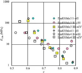
Fig. 9. Oedometer modulus versus void ratio for Ess83.
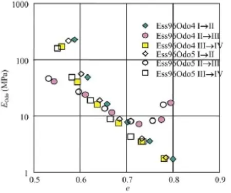
Fig. 10. Oedometer modulus versus void ratio for Ess96.
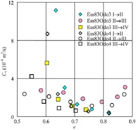
Fig. 11. Consolidation coefficient versus void ratio for Ess83.
Changes in the secondary deformation coefficient Cαwith void ratio e are depicted in Figs. 13 and 14 for Ess83 and Ess96, respectively. For Ess83, the absolute values of Cα from test Ess83Odo4 with distilled water are larger than those from test Ess83Odo3 with synthetic water, especially for the unloading paths (I→II and III→IV). By contrast, for Ess96, this phenomenon is not obvious and the points corresponding to two water chemistries almost overlap.
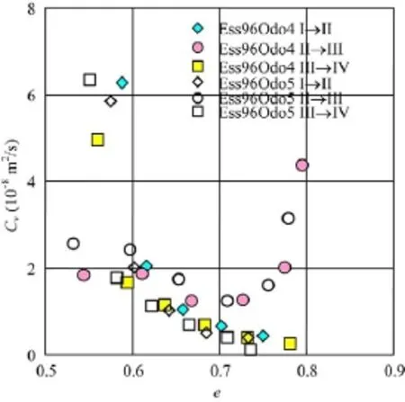
Fig. 12. Consolidation coefficient versus void ratio for Ess96.

Fig. 13. Secondary consolidation coefficient versus void ratio for Ess83.
Examination of the mineralogical composition of Ess83 and Ess96 showed that the smectite content is likely the main factor to be considered in investigating the pore-water chemistry effects on the hydro-mechanical behaviour of BC. As Ess83 contains more smectite (10% more, see Table 2), it appears normal that the Ess83 shows more effects of pore-water chemistry. But on the whole, these effects are quite limited.
7. Volume change behaviour of bentonite-based materials
The volume change behaviour of compacted MX80 bentonite was investigated using an isotropic cell that enables suction and temperature to be controlled (Tang et al., 2007; Tang and Cui, 2010a). The results of thermal volume change under a pressure p = 0.1 MPa are presented in Fig. 15. The results from tests T1 (suction s = 110 MPa) and T2 (s = 39 MPa) show that heating induced an expansion. Considering that this expansion is linear, a coefficient of thermal expansion α = 2 × 10⁻⁴°C−1can be deduced. On the contrary, the result from test T3 (s = 9 MPa) shows that heating induced a contraction. In addition, the subsequent cooling–reheating cycle undertaken shows a reversible behaviour. Note that significant data scatter was observed in this test and it is thus difficult to quantify the volume change behaviour during the cooling–reheating stage.

Fig. 14. Secondary consolidation coefficient versus void ratio for Ess96.
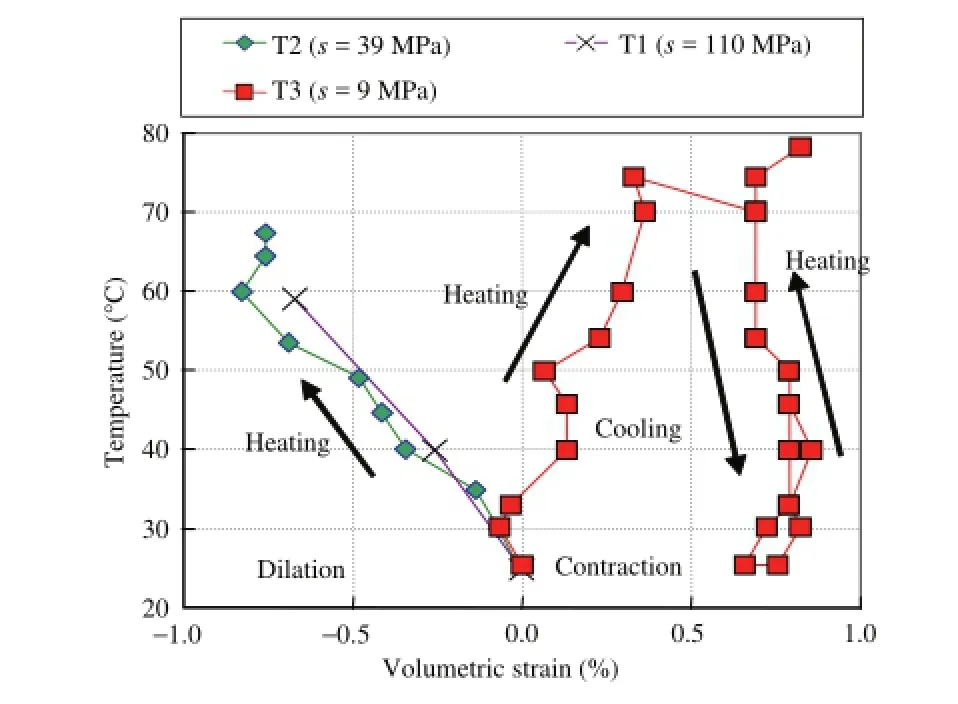
Fig. 15. Volumetric strain during thermal loading under constant pressure at 0.1 MPa of tests T1, T2 and T3.
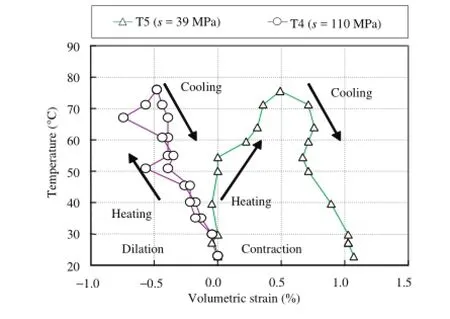
Fig. 16. Volumetric strain during thermal loading under constant pressure at 5 MPa of tests T4 and T5.
Fig. 16 presents the results obtained from tests T4 (s = 110 MPa) and T5 (s = 39 MPa) at p = 5 MPa. It can be observed that, at high suction, heating from T = 25°C to 80°C induced an expansion and cooling from T = 80°C to 25°C induced a contraction. The volume change during this thermal cycle is approximately reversible; a coefficient of thermal expansion α = 2 × 10⁻⁴°C−1can be estimated. At a suction of 39 MPa (test T5), as opposed to the case in test T2 (s = 39 MPa, p = 0.1 MPa), heating from T = 25°C to 80°C resulted in a thermal contraction and cooling from T = 80°C to 25°C also resulted in a contraction. The volumetric strain and the temperature during cooling from T = 55°C to 25°C can be correlated with a linear function, defining a coefficient of thermal expansion α = 2 × 10⁻⁴°C−1which is similar to that deduced from tests T1, T2 and T4.
Based on the compression curves in the e–ln p plane, the plastic compression coefficient λ(s) and elastic coefficient κ were determined. It was observed that these parameters are independent of temperature but strongly dependent on suction (see Fig. 17 for the tests at 25°C). It appears that wetting increases the two compressibility parameters.

Fig. 17. Compressibility parameters (κ and λ(s)) versus suction for the tests at 25°C.

Fig. 18. Yield pressure (p0) versus temperature for different suctions.
The values of yield pressure (p0) determined versus temperature for different suctions are shown in Fig. 18. It can be observed that p0decreases upon heating and wetting.
8. Hydraulic behaviour
The hydraulic conductivity of compacted bentonite Kunigel V1 at different initial water contents was determined by the simultaneous profile method (Cui et al., 2008). The results are presented in Fig. 19. It can be observed that unsaturated hydraulic conductivity kunsatdetermined by Loiseau et al. (2002) is decreasing over time. The decrease of kunsatduring the tests was equally observed by Haug and Wong (1992) and Hoffmann et al. (2007) on compacted expansive soils. Lloret and Villar (2007) mentioned that the permeability of compacted bentonite measured under water saturated conditions is much lower than that measured by gas under unsaturated or dry conditions. This phenomenon can be explained by the decrease of the volume of macro-pores during wetting as observed by Cui et al. (2002).
From the analysis mentioned above, it can be concluded that kinicorresponds to the initial microstructure of the compacted sand/bentonite mixture. Note that the plot of test T04 in Fig. 19 corresponds to the k-s curve of a soil sample having a microstructure similar to the initial microstructure of a compacted soil sample at e = 0.34. Moreover, the soils tested by Loiseau et al. (2002) and in test T04 have similar initial state (e = 0.34, wi= 8.0 ± 0.3%). It can be observed that the k–s curve determined from test T04 trends to reach kiniwhen suction is decreased to zero. This confirms that the microstructure of the soil tested in the two tests is similar.
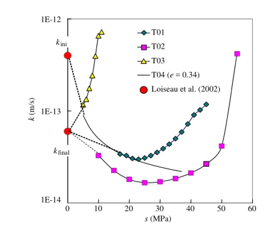
Fig. 19. Hydraulic conductivity versus suction.
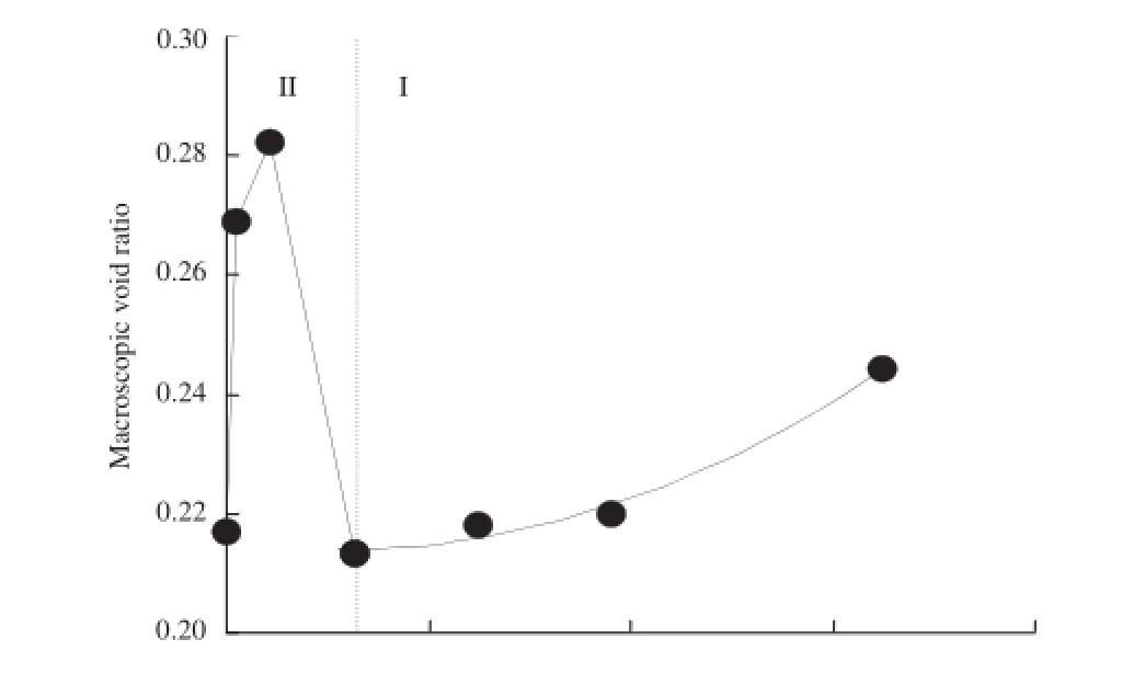
Fig. 20. Changes of macroscopic void ratio with suction.
On the other hand, kfinalcorresponds to the final microstructure of the soil after wetting under constant-volume conditions; the macro-pore family was almost eliminated. Interestingly, the k-s curves obtained from the three tests performed at constant-volume conditions (T01, T02 and T03) trend to join kfinalwhen suction is decreased to zero, whatever the water content is.
Upon wetting, the suction is decreasing and hydraulic conductivity kunsatis in general increasing because water retention force is reduced (Daniel, 1982; Benson and Gribb, 1997; Chiu and Shackelford, 1998). On the other hand, wetting under constantvolume conditions reduces the volume of the macro-pores family (Cui et al., 2002), giving rise to a decrease of kunsat. These two opposing mechanisms explain the results on constant-volume conditions presented in Fig. 19: during wetting, k decreases initially because of the reduction of the volume of macro-pores. As the volume of macro-pores is dependent on the initial water content (Delage et al., 1996), the decrease of k with suction is different for different initial water contents. Thereby, test T03 shows a constant decrease whereas tests T01 and T02 show that k started to increase from s = 22 MPa.
In order to verify the wetting effect on the macro-pores, mercury intrusion porosimetry (MIP) was conducted on the compacted MX80/sand mixture wetted at different suctions. The pores larger than 2 μm are defined as macro-pores. Fig. 20 shows that the macroscopic void ratio (emacro) defined by the volume of macropores changes with decreasing suction. It can be observed that the macro-pores quantity is progressively reduced with decreasing suction in zone I and then increased in zone II. The increase in zone II can be explained by the creation of the 2D (two-dimensional) pores due to aggregating fissuring (Wang, 2012). These changes of emacroupon wetting explain the decrease of hydraulic conductivity shown in Fig. 19.
9. Technological void effect
As engineered barriers are often made up of compacted bricks, when the bricks are placed around waste canisters or to form sealing buffers, the so-called technological voids either between the bricks themselves or between bricks, canisters and the host rock are unavoidable. As an example, 10 mm thick gaps between bentonite blocks and canister and 25 mm thick gaps between the bentonite blocks and the host rock have been considered in the basic design of Finland (Juvankoski, 2010). These technological voids appeared to be equal to 6.6% of the volume of the gallery in the FEBEX mockup test (Martin et al., 2006). Fractures that appear in the excavation damaged zone within the host rock in the near field constituteadditional voids. In the French concept, the volume of the bentonite/rock gaps is estimated at 9% of the volume of the gallery by the French waste management agency (ANDRA, 2005). This value reaches 14% in the SEALEX in situ test carried out in the Tournemire URL (Barnichon and Deleruyelle, 2009). This technological void can significantly influence the hydro-mechanical behaviour of bentonite-based material and needs to be investigated in depth.

Fig. 21. Hydraulic conductivity versus dry density of mixture.
9.1. Effect of technological void on hydraulic conductivity
Compacted MX80/sand mixture was considered to study the effect of technological void on hydraulic conductivity. With a ring diameter of 38 mm, the annular technological void selected (14% of the total cell volume representing 17% of the initial sample volume) corresponds to a sample diameter of 35.13 mm. Four tests with the same technological void of 14% were conducted on samples with the same initial water content of 11% and various initial dry densities obtained by changing the compaction pressure (between 65 MPa and 85 MPa, giving rise to dry densities comprised between 1.93 Mg/m3and 1.98 Mg/m3).
The saturated hydraulic conductivity was determined after saturation of the samples, by both the constant head test and the indirect Casagrande’s method. Fig. 21 compares the results obtained with that obtained by Gatabin et al. (2008) by constant head test on homogeneous samples at similar densities. The data obtained for the heterogeneous samples with both methods are in good agreement. On the whole, the hydraulic conductivity decreases with density increase, following a slope comparable to that obtained by Gatabin et al. (2008). Further examination shows that the samples with initial technological voids exhibit higher hydraulic conductivity than that by Gatabin et al. (2008), with a difference of one order of magnitude. This difference is suspected to be due to a preferential water flow in the looser zone (initial technological voids) around the samples.
9.2. Effect of technological void on swelling pressure

Fig. 22. Relationship between vertical stress and bentonite (MX80) void ratio.
In order to analyse the effect of technological void on swelling pressure, various constitutive parameters of the compacted mixture are defined. It is supposed that the volume of bentonite (Vb) in the mixture is equal to the difference between the total volume (V) and the volume of sand (Vs). Vbis equal to the sum of the bentonite particle volume (Vbs) and the volume of void, namely intra-void volume (Vi). The bentonite void ratio (eb) consists of two parts (Eq. (2)), the intra-bentonite void ratio inside the soil (ebi) and the void ratio corresponding to the technological void (etech). Eqs. (3) and (4) define these two voids, respectively.

where Vtechis the volume of technological voids. The value of ebican be deduced from the initial dry unit mass of the mixture (ρdm) using the following equations:

where ρwis the water unit mass; Gsb is the specific gravity of bentonite; ρdbis the initial dry unit mass of bentonite in the mixture, which was calculated using Eq. (6) (Dixon et al., 1985; Lee et al., 1999; Agus and Schanz, 2008; Wang et al., 2012); ρmis the unit mass of the mixture; B (%) is the bentonite content (in dry mass) in the mixture; Gss is the specific gravity of sand; wm is the water content of the mixture. In this study, the decrease of water unit mass (ρw) during hydration (e.g. Skipper et al., 1991; Villar and Lloret, 2004) was not considered and the value was assumed to be constant (1.0 Mg/m3), B = 70%, Gss= 2.65.
The values of vertical stress measured at the end of the hydration tests on samples with technological voids are presented in Fig. 22 with respect to the bentonite void ratio. The data of swelling pressure measured in homogeneous samples under the same conditions of constant volume by other authors are also plotted for comparison (MX80 70/30 bentonite/sand mixture from Karnland et al. (2008), and pure MX80 bentonite from Börgesson et al. (1996), Dixon et al. (1996), Karnland et al. (2008), and Komine et al. (2009)).
All data remarkably agree, giving a unique relationship between the vertical pressure and the bentonite void ratio, regardless of the sample nature (homogeneous or not). The correspondence with data from Karnland et al. (2008) (pure bentonite and 70/30 bentonite sand mixture) at bentonite void ratio close to 1 is particularly good. This confirms that the stress at equilibrium is not affected bythe heterogeneity of the samples. The swelling pressure depends only on the global bentonite void ratio (eb), regardless of the technological void and the presence of sand.
10. Conclusions
An overview of the recent findings about the CTHM behaviour of materials used for both geological and engineered barriers in nuclear waste disposal is presented, through some examples about the natural BC and the compacted bentonite-based materials.
For the natural BC, it was found that: (1) compression index identified from both oedometer and isotropic compression tests is similar and the compressibility of BC from the Mol site is higher than that of BC from the Essen site; (2) the shear strength of Mol BC is also higher than that of the Essen BC, suggesting a significant effect of carbonates content; (3) the thermal volume change is strongly OCR dependent: low OCR values promote thermal contraction while high OCR values favour thermal dilation. The volume change behaviour is also strongly time dependent and this time dependent behaviour is governed by the stress level and temperature. The effect of pore-water salinity on the volume change behaviour can be significant when the smectite content is relatively high. However, the pore-water chemistry does not seem to affect the hydraulic conductivity.
For the bentonite-based materials, it was found that thermal contraction occurs also at low OCR values, but this is suction dependent—suction promotes thermal dilation. Under constant volume conditions, wetting results in a decrease of hydraulic conductivity followed by an increase. This is found to be related to changes in macro-pores size—wetting induces a decrease of macropores size followed by an increase due to the aggregates fissuring.
The presence of technological voids can form a loose zone with benonite gel after hydration. This zone corresponds to the preferential path for water flow, with a relatively higher hydraulic conductivity. However, the swelling pressure depends only on the global bentonite void ratio, regardless of the technological void.
Agus SS. An experimental study on hydro-mechanical characteristics of compacted bentonite–sand mixtures. Weimar: University of Weimar; 2005 (PhD Thesis).
Agus SS, Schanz T. A method for predicting swelling pressure of compacted bentonites. Acta Geotechnica 2008;3(2):125–37.
Agus SS, Schanz T, Fredlund DG. Measurements of suction versus water content for bentonite–sand mixtures. Canadian Geotechnical Journal 2010;47(5):583–94.
ANDRA. Référentiel des matériaux d’un stockage de déchets à haute activité et à vie longue—Tome 4: Les matériaux à base d’argilites excavées et remaniées. Rapport ANDRA N°CRPASCM040015B; 2005.
Baldi G, Hueckel T, PellegriniR. Thermal volume changes of the mineralwater system in low-porosity clay soils. Canadian Geotechnical Journal 1988;25(4):807–25.
Baldi G, Hueckel T, Peano A, PellegriniR. Developments in modelling of thermohydro-geomechanical behaviour of Boom Clay and clay-based buffer materials. Commission of the European communities, nuclear science and technology EUR 13365/2, vol. 2; 1991.
Barnichon JD, Deleruyelle F. Sealing experiments at the Tournemire URL. EUROSAFE; 2009.
Benson CH, Gribb MM. Measuring unsaturated hydraulic conductivity in the laboratory and field. In: Unsaturated soil engineering practice. New York: ASCE, Geotechnical Special Publication; 1997. p. 113–68.
Bouazza A, Van Impe WF, Hageman W. Some mechanical properties of reconstituted Boom Clay. Journal of Geotechnical and Geological Engineering 1996;14(4):341–52.
Börgesson L, Karnland O, Johannesson LE. Modelling of the physical behaviour of clay barriers close to water saturation. Engineering Geology 1996;41(1–4):127–44.
Börgesson L, Chijimatsu M, Fujita T, Nguyen TS, Rutqvist J, Jing L. Thermo-hydromechanical characterisation of bentonite-based buffer material by laboratory tests and numerical back analyses. International Journal of Rock Mechanics and Mining Sciences 2001;38(1):95–104.
Chiu TF, Shackelford CD. Unsaturated hydraulic conductivity of compacted sand–kaolin mixtures. Journal of Geotechnical and Geoenvironmental Engineering 1998;124(2):160–70.
Coll C. Endommagement des roches argileuses et perméabilité induite au voisinage d’ouvrage souterrains. Grenoble: Université Joseph Fourier-Grenoble 1; 2005 (PhD Thesis).
Cui YJ, Sultan N, Delage P. A thermomechanical model for clays. Canadian Geotechnical Journal 2000;37(3):607–20.
Cui YJ, Loiseau C, Delage P. Microstructure changes of a con fined swelling soil due to suction controlled hydration. In: Jucá JFT, de Campos TMP, Marinho FAM, editors. Unsaturated soils. Proc. 3rd int. conf. on unsaturated soils (UNSAT 2002). Lisse: Swets & Zeitlinger; 2002. p. 593–8.
Cui YJ, Tang AM, Loiseau C, Delage P. Determining the unsaturated hydraulic conductivity of a compacted sand-bentonite mixture under constant-volume and free-swell conditions. Physics and Chemistry of the Earth, Parts A/B/C 2008;33(Suppl. 1):462–71.
Cui YJ, Le TT, Tang AM, Delage P, Li XL. Investigating the time dependent behaviour of Boom Clay under thermo-mechanical loading. Geotechnique 2009;59(4):319–29.
Cui YJ, Tang AM, Qian LX, Ye WM, Chen B. Thermal–mechanical behavior of compacted GMZ bentonite. Soils and Foundations 2011;51(6):1065–74.
Daniel DE. Measurement of hydraulic conductivity of unsaturated soils with thermocouple psychrometers. Soil Science Society of America Journal 1982;20(6):1125–9.
De Craen M, Wemaere I, Labat S, Van Geet M. Geochemical analyses of Boom Clay pore water and underlying aquifers in the Essen-1 borehole. SCK·CEN external report (REPORT SCK·CEN-ER-19), Belgium; 2006.
Delage P, Audiguier M, Cui YJ, Howat M. Microstructure of a compacted silty clay. Canadian Geotechnical Journal 1996;33(1):150–8.
Delage P, Howat MD, Cui YJ. The relationship between suction and swelling properties in a heavily compacted unsaturated clay. Engineering Geology 1998;50(1–2):31–48.
Delage P, Marcial D, Cui YJ, Ruiz X. Ageing effects in a compacted bentonite: a microstructure approach. Geotechnique 2006;56(5):291–304.
Demars KR, Charles RD. Soil volume changes induced by temperature cycling. Canadian Geotechnical Journal 1982;19(2):188–94.
Deng YF, Tang AM, Cui YJ, Li XL. A study on the hydraulic conductivity of Boom Clay. Canadian Geotechnical Journal 2011a;48(10):1461–70.
Deng YF, Tang AM, Cui YJ, Nguyen XP, Li XL, Wouters L. Laboratory hydro-mechanical characterisation of boom clay at essen and mol. Physics and Chemistry of the Earth 2011b;36(17–18):1878–90.
Deng YF, Cui YJ, Tang AM, Nuyen XP, Li XL, Van Geet M. Investigating the pore-water chemistry effects on the volume change behaviour of Boom Clay. Physics and Chemistry of the Earth 2011c;36(17–18):1905–12.
Deng YF, Cui YJ, Tang AM, Li XL, Sillen X. An experimental study on the secondary deformation of Boom Clay. Applied Clay Science 2012;59–60:19–25.
Dixon DA, Gray MN, Thomas AW. A study of the compaction properties of potential clay–sand buffer mixtures for use in nuclear fuel waste disposal. Engineering Geology 1985;21(3–4):247–55.
Dixon DA, Cheung SCH, Gray MN, Davidson BC. The hydraulic conductivity of dense clay soils. In: Proc. 40th Canadian geotechnical conference; 1987. p. 389–96.
Dixon DA, Gray MN, Hnatiw D. Critical gradients and pressures in dense swelling clays. Canadian Geotechnical Journal 1992;29(6):1113–9.
Dixon DA, Gray MN, Graham J. Swelling and hydraulic properties of bentonites from Japan, Canada and USA. In: Proceedings of the second international congress on environmental geotechnics; 1996. p. 5–8.
Dixon DA, Graham J, Gray MN. Hydraulic conductivity of clays in confined tests under low hydraulic gradients. Canadian Geotechnical Journal 1999;36(5):815–25.
Francois B, Laloui L, Laurent C. Thermo-hydro-mechanical simulation of ATLAS in situ large scale test in Boom Clay. Computers and Geotechnics 2009;36(4):626–40.
Gatabin C, Touze G, Imbert C, Guillot W, Billaud P. ESDRED project, module 1—selection and THM characterization of the buffer material. In: International conference underground disposal unit design & emplacement processes for a deep geological repository; 2008. p. 16–8.
Haug MD, Wong LC. Impact of molding water content on hydraulic conductivity of compacted sand-bentonite. Canadian Geotechnical Journal 1992;29(2): 253–62.
Hoffmann C, Alonso EE, Romero E. Hydro-mechanical behaviour of bentonite pellet mixtures. Physics and Chemistry of the Earth 2007;32(8–14):832–49.
Horseman ST, Winter MG, Entwistle DC. Geotechnical characterization of Boom Clay in relation to the disposal of radioactive waste. Commission of the European Communities; 1987. p. 87.
Juvankoski M. Description of basic design for buffer (working report 2009-131). Technical report. Finland: EURAJOKI; 2010.
Karnland O, Nilsson U, Weber H, Wersin P. Sealing ability of Wyoming bentonite pellets foreseen as buffer material—laboratory results. Physics and Chemistry of the Earth, Parts A/B/C 2008;33(Suppl. 1):472–5.
Komine H, Yasuhara K, Murakami S. Swelling characteristics of bentonites in arti ficial seawater. Canadian Geotechnical Journal 2009;46(2):177–89.
Komine H, Watanabe Y. The past, present and future of the geo-environment in Japan. Soils and Foundations 2010;50(6):977–82.
Komine H. Predicting hydraulic conductivity of sand bentonite mixture back fill before and after swelling deformation for underground disposal of radioactive wastes. Engineering Geology 2010;114(3–4):123–34.
Lee JO, Cho WJ, Chun KS. Swelling pressures of a potential buffer material for high-level waste repository. Journal of the Korean Nuclear Society 1999;31(2):139–50.
Lloret A, Villar M. Advances on the knowledge of the thermo-hydro-mechanical behaviour of heavily compacted FEBEX bentonite. Physics and Chemistry of the Earth 2007;32(8–14):701–15.
Loiseau C, Cui YJ, Delage P. The gradient effect on the water flow through a compacted swelling soil. In: Jucá JFT, de Campos TMP, Marinho FAM, editors. Unsaturated soils. Proc. 3rd int. conf. on unsaturated soils (UNSAT 2002). Lisse: Swets & Zeitlinger; 2002. p. 395–400.
Marcial D, Delage P, Cui YJ. On the high stress compression of bentonites. Canadian Geotechnical Journal 2002;39(4):812–20.
Marcial D. Comportement hydromécanique et microstructural des matériaux de barrière ouvragée; 2003 (thèse ENPC).
Martin PL, Barcala JM, Huertas F. Large-scale and long-term coupled thermohydro-mechanic experiments with bentonite: the Febex mock-up test. Journal ofiberian Geology 2006;32(2):259–82.
Montes HG, Duplay J, Martinez L, Mendoza C. Swelling—shrinkage kinetics of MX80 bentonite. Applied Clay Science 2003;22(6):279–93.
Paaswell RE. Temperature effects on clay soil consolidation. Journal of Soil Mechanics and Foundation Engineering, ASCE 1967;93(SM3):9–22.
Plum RL, Esrig MI. Some temperature effects on soil compressibility and pore water pressure. In: Effects of temperature and heat on engineering behavior of soils, special report 103. Highway Research Board; 1969. p. 231–42.
Pusch R. Highly compacted sodium bentonite for isolating rock-deposited radioactive waste products. Nuclear Technology 1979;45(2):153–7.
Romero E, Gens A, Lloret A. Water permeability, water retention and microstructure of unsaturated compacted Boom Clay. Engineering Geology 1999;54(1–2):117–27.
Romero E, Della Vecchia G, Jommi C. An insight into the water retention properties of compacted clayey soils. Geotechnique 2011;61(4):313–28.
Skipper NT, Refson K, McConnell JDC. Computer simulation ofinterlayer water in 2:1 clays. Journal of Chemical Physics 1991;94(11):7434–45.
Sultan N. Etude du comportement thermo-mécanique de l’argile de Boom: expériences et modélisation. Paris: Ecole Nationale des Ponts et Chaussées; 1997 (PhD Thesis).
Sultan N, Delage P, Cui YJ. Comportement thermomécanique de l’argile de Boom. Comptes-Rendus de l’Académie des Sciences. Série II B-Mécanique 2000;328(6):457–63.
Sultan N, Delage P, Cui YJ. Temperature effects on the volume change behaviour of Boom Clay. Engineering Geology 2002;64(2–3):135–45.
Tang AM, Cui YJ, Barnel N. A new suction–temperature controlled isotropic cell used to study the thermo-mechanical behaviour of unsaturated expansive clays. Geotechnical Testing Journal 2007;30(5):341–8.
Tang AM, Cui YJ. Experimental study on the hydro-mechanical coupling behaviour of highly compacted expansive clay. Journal of Rock Mechanics and Geotechnical Engineering 2010a;2(1):39–43.
Tang AM, Cui YJ. Effects of mineralogy on thermo-hydro-mechanical parameters of MX80 bentonite. Journal of Rock Mechanics and Geotechnical Engineering 2010b;2(1):91–6.
Towhata I, Kuntiwattanakul P, Seko I, Ohishi K. Volume change of clays induced by heating as observed in consolidation tests. Soils and Foundations 1993;33(4):170–83.
Van Impe WF. Boom Clay for storage of nuclear waste (discussion session 2b). In: Athen Al AE, editor. Geotechnical engineering of hard soils-soft rocks. Rotterdam: A.A. Balkema; 1993. p. 1885–95.
Villar MV, Lloret A. In fluence of temperature on the hydro-mechanical behaviour of a compacted bentonite. Applied Clay Science 2004;26(1–4):337–50.
Villar MV. MX-80 bentonite, thermo-hydro-mechanical characterisation performed at CIEMAT in the context of the prototype project. CIEMAT Technical Report: CIEMAT/DIAE/54540/2/04; 2005.
Villar MV, Lloret A. In fluence of dry density and water content on the swelling of a compacted bentonite. Applied Clay Science 2008;39(1–2):38–49.
Wang Q. Hydro-mechanical behaviour of bentonite-based materials used for highlevel radioactive waste disposal. Ph. D. Thesis. Paris: Université Paris-Est; 2012.
Wang Q, Tang AM, Cui YJ, Delage P, Gatmiri B. Experimental study on the swelling behaviour of bentonite/claystone mixture. Engineering Geology 2012;124:59–66.
Ye WM, Cui YJ, Qian LX, Chen B. An experimental study of the water transfer through con fined compacted gmz bentonite. Engineering Geology 2009;108(3–4):169–76.
Yong RN, Boonsinsuk P, Wong G. Formulation of back fill material for a nuclear fuel waste disposal vault. Canadian Geotechnical Journal 1986;23(2): 216–28.

Yu-Jun Cui is working as a professor at Ecole des Ponts ParisTech (ENPC), France. His research interests cover unsaturated soil mechanics, laboratory testing, constitutive modelling, environmental geotechnics, railway geotechnics, nuclear waste disposal, lime/cement stabilized soils, soil–vegetation–atmosphere interaction, compaction of agricultural soils, etc.
∗Corresponding author at: Laboratoire Navier/CERMES, Ecole des Ponts ParisTech, 6 et 8 avenue Blaise Pascal, Cité Descartes, Champs-sur-Marne, 77455 Marne-la-Vallée cedex 2, France. Tel.: +33 01 64153550.
E-mail address: yujun.cui@enpc.fr (Y.-J. Cui).
Peer review under responsibility ofinstitute of Rock and Soil Mechanics, Chinese Academy of Sciences.
1674-7755 © 2013 Institute of Rock and Soil Mechanics, Chinese Academy of Sciences. Production and hosting by Elsevier B.V. All rights reserved.
http://dx.doi.org/10.1016/j.jrmge.2013.05.001
 Journal of Rock Mechanics and Geotechnical Engineering2013年3期
- Journal of Rock Mechanics and Geotechnical Engineering的其它文章
- Millau viaduct geotechnical studies and foundations
- TIMODAZ: A successful international cooperation project to investigate the thermal impact on the EDZ around a radioactive waste disposal in clay host rocks
- Short- and long-term behaviors of drifts in the Callovo-Oxfordian claystone at the Meuse/Haute-Marne Underground Research Laboratory
- Sealing of fractures in claystone
- Joints in unsaturated rocks: Thermo-hydro-mechanical formulation and constitutive behaviour
- Homogenization in clay barriers and seals: Two case studies
