
Influence of high-porosity mesh stent on hemodynamics of intracranial aneurysm: A computational study*
2013-06-01 12:29:59QIUXiaoning邱晓宁
水动力学研究与进展 B辑 2013年6期
QIU Xiao-ning (邱晓宁)
Key Laboratory of Education Ministry of China for Power Machinery and Engineering, Shanghai Jiao Tong University, Shanghai 200240, China, E-mail: xiaoning0018@126.com
FEI Zhi-min (费智敏)
Shuguang Hospital, Shanghai University of Traditional Chinese Medicine, Shanghai 203204, China
ZHANG Jue (张珏)
Renji Hospital, Shanghai Jiaotong University, Shanghai 200127, China
CAO Zhao-min (曹兆敏)
Key Laboratory of Education Ministry of China for Power Machinery and Engineering, Shanghai Jiao Tong University, Shanghai 200240, China
Influence of high-porosity mesh stent on hemodynamics of intracranial aneurysm: A computational study*
QIU Xiao-ning (邱晓宁)
Key Laboratory of Education Ministry of China for Power Machinery and Engineering, Shanghai Jiao Tong University, Shanghai 200240, China, E-mail: xiaoning0018@126.com
FEI Zhi-min (费智敏)
Shuguang Hospital, Shanghai University of Traditional Chinese Medicine, Shanghai 203204, China
ZHANG Jue (张珏)
Renji Hospital, Shanghai Jiaotong University, Shanghai 200127, China
CAO Zhao-min (曹兆敏)
Key Laboratory of Education Ministry of China for Power Machinery and Engineering, Shanghai Jiao Tong University, Shanghai 200240, China
(Received September 23, 2012, Revised April 2, 2013)
This paper studies the influence of a High-Porosity Mesh (HPM) stent on the hemodynamic characteristics in the intracranial aneurysm based on the Computational Fluid Dynamics (CFD). An idealized basilar tip aneurysm model and a HPM stent model are built. The pulsating blood flow in a cardiac cycle is computationally simulated for non-stented and stented models, to provide a wealth of information of the spatio-temporally varying blood flow field. The influence of the stent placement on the hemodynamic characteristics is analyzed in terms of distributions of velocity, pressure, Wall Shear Stress (WSS) and Energy Loss (EL), which are believed to play an important role in the development and rupture of the aneurysm. The numerical results clearly show that the velocity, pressure, WSS and EL of the blood flow in the aneurysm are reduced by 30%-40% when the HPM stent is implanted. These computational results may provide valuable hemodynamic information for clinical neurosurgeon.
Computational Fluid Dynamics (CFD), stent, basilar tip aneurysm, hemodynamics
Introduction
The Cerebral Aneurysms (CA) are pathological local dilations of the intracranial arteries, which usually occur at the circle of Willis[1,2]. The most severe complication is their rupture caused by subarachnoid haemorrhage (SAH), with a concomitant high mortality and morbidity rates[1-4]. The traditional surgeries for the CA include the clipping aneurysm and the coil embolization[4,5]. However, the clipping process invo-lves craniotomy, featured by a long time recovery and the particular restriction on the location and the shape of the aneurysm; the coil embolization would likely result in the aneurysm re-growth, not suitable for wide-necked aneurysms[6]. Accordingly, the attentions are turned to the High-Porosity Mesh (HPM) stents in order to avoid the above–mentioned problems. It is believed that the HPM stent is a minimally invasive therapy and it needs less postoperative recovery time than the traditional operation methods[7,8].
The function of the HPM stent is to disrupt the inflow to the aneurysm and to cause a complete thrombosis in the aneurysm[9]. Manyin vitroexperiments and numerical simulations show that the HPM stents can change the flow in the aneurysm[7-10]. Lieber and Gounis[11]performed the flow visualization experiment to investigate the influence of the stent porosity (75%-85%) on the variation of the intracranial aneurismal flow pattern. Morrios et al.[12]measured thesteady flow fields in the non-stented and stented lateral aneurysms by using the particle image velocimetry. Liou et al.[13]used the particle tracking velocimetry to determine the influence of the stent implantation position on the aneurysm flow fields. Mori and Matsuzawa[14]studied the effect of the stent implantation on the idealized sidewall cerebral aneurysm using the Computational Fluid Dynamics (CFD) technique, and it was shown that the velocity, pressure and WSS of the blood flow in the aneurysm are decreased significantly when the stent is implanted. Hirabayashi et al.[15]studied the blood flow in a two-dimensional stented aneurysm by using the lattice Boltzmann method, showing a reduction of the velocity in the stented aneurysm. These studies show that the stent treatment alone can markedly alter the aneurysm hemodynamics and provide valuable hemodynamic characteristics of the stented aneurysm to be used in the clinical neurosurgeon. However, most of the previous studies were carried out for the sidewall aneurysm. It is shown that the aneurysm frequently appears in the bifurcation area of arteries, and the bifurcation aneurysms may have a higher rate of rupture than the sidewall aneurysm[16]. Accordingly, a better understanding of the influence of the HPM stent on the hemodynamic characteristics in the bifurcated artery aneurysms is highly desirable.
In the present study, a computational hemodynamic analysis system[17]is applied to investigate the influence of the HPM stent configuration on the intracranial aneurysmal hemodynamics based on a simplified basilar tip aneurysm model. The influence of the HPM stent is studied in terms of hemodynamic indices, i.e., the velocity, the Wall Shear Stress (WSS), the pressure and the Energy Loss (EL), these indices are believed not only have critical effects on the function of the endothelium and the endothelial cell gene, but also play a fundamental role in the aneurysmal genesis, the growth and the ultimate rupture[1-10]. The aim of this study is to disclose the hemodynamic characteristics in the aneurysm region in order to predict the outcomes when the stent is implanted into the artery, and to confirm the applicability of the computational hemodynamic analysis system in selecting optimal stents for surgeries.
1. Models and methods
1.1Aneurysm and stent modeling
The structure of the Basilar Tip Aneurysm (BTA) is based on a patient-specific clinical data, which is shown in Fig.1(a). In order to quantitatively analyze the hemodynamic characteristics of the stent on the BTA, a simplified Idealized Basilar Tip Aneurysm (IBTA) model (shown in Fig.1(b)) is constructed[5]. The IBTA model and the stent are created using a Computer-Aided Design (CAD) software Pro-Engineer (Parametric Technology Corporation, USA). In the IBTA model, the angle of the bifurcation between the Left Posterior Cerebral Artery (LPCA) and the Right Posterior Cerebral Artery (RPCA) is 120o. An 8 mm diameter spherical aneurysm sac is placed at the bifurcation area of the basilar artery. The diameters of the basilar artery, the LPCA and the RPCA are all 4 mm. To ensure that the flow is fully developed before entering the aneurysm region, the basilar length is set to 20 times of the diameter of the basilar artery. Figure 1(c) illustrates the stented model and the virtual neuroform stent used in this study, the constructed stent is 3.9 mm in diameter, 12 mm in length, 0.2 mm in wire thickness, and 0.1 mm in wire height. The porosity of the neuroform stent is 87%, which is similar to the stent studied by Augsburger et al.[18].
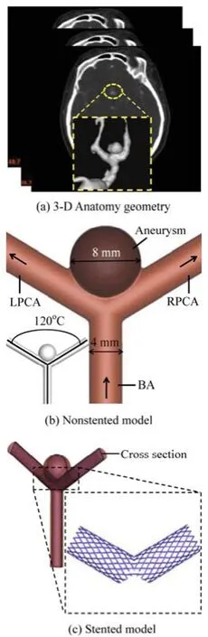
Fig.1 Geometry of the non-stented and stented basilar aneurysm models
1.2Blood flow governing equations
The blood flow in the BTA is governed by the three-dimensional incompressible Navier-Stokes equations and the continuity equation
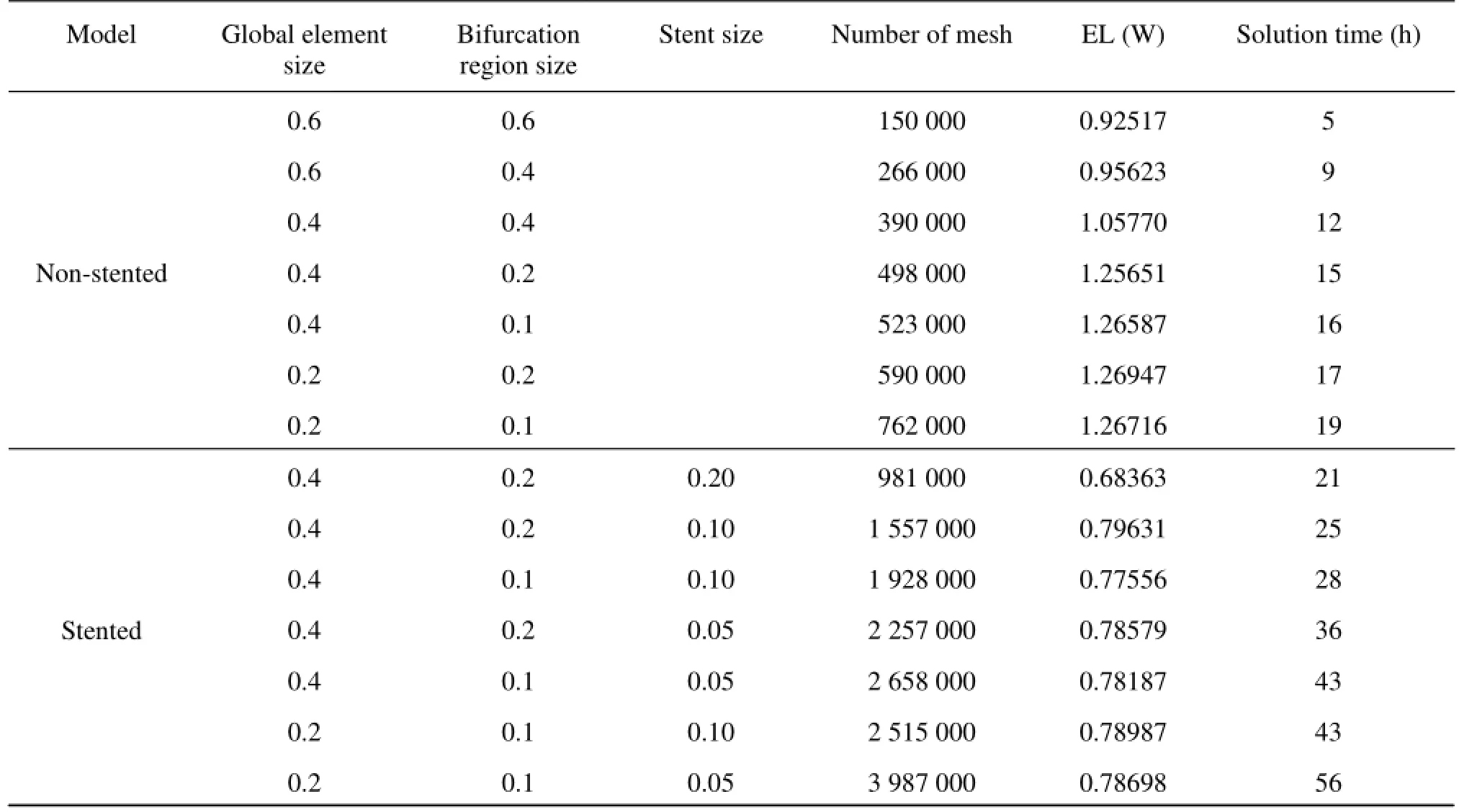
Table1 Mesh information used for sensitivity analysis
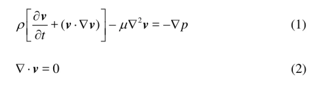
wherevis the velocity vector,ρis the fluid density,tis the time,μis the fluid dynamic viscosity andpis the pressure. In the calculation, the blood is regarded as a Newtonian fluid, as was shown to be a reasonable approximation for flow simulations[4-8]. The density and the viscosity of the blood are 1 060 kg/m3and 0.004 Pa·s, respectively. The maximum Reynolds number is less than 400, hence the flow can be assumed as a laminar flow.
1.3Data analysis
To better assess the influence of the HPM stent configuration, the hemodynamic indices, i.e., the blood velocity, the WSS, the pressure, are analyzed, these indices play an important role in the evolution of cardiovascular diseases.
The parameter EL[19,20]is defined as

whereP,VandQare the static pressure, the velocity and the flow rate, respectively,iindicates the inlet of the basilar artery,oindicates the outlet at the LPCA and RPCA.
The WSS is a flow-induced stress that can be described as the frictional force of the viscous blood and can be determined from the near wall tangential velocity, which is recognized as the main risk factor for the aneurysm occurrence, growth and rupture[2-8]. The WSS is defined as
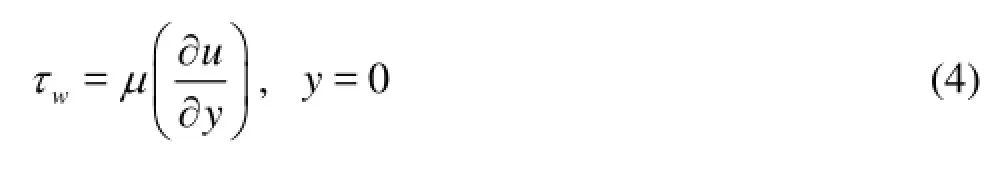
whereμis the dynamic viscosity,uis the flow parallel to the arterial wall andyis the distance to the arterial wall.
1.4Mesh generation and grid sensitivity analysis
The computational mesh for the numerical simulation is generated by the commercial software, ANSYS ICEM 12.0 (ANSYS Inc., USA), in tetrahedral grids. In order to accurately evaluate the WSS and the pressure at the near-wall regions, the boundary-fitted prism layers are generated to improve the resolution of the relevant scales in the fluid motion. In the simulation, five layers are generated with an average node space increasing by a ratio of 1.1. The distance of the first layer to the artery surface was 0.02 mm. In order to improve the accuracy of the calculation results of the simplified model, the grid sensitivity analysis is carried out. Different mesh sizes are used indifferent parts of the non-stented and stented models. Seven groups of different tetrahedral mesh sizes are considered. The magnitude of the EL is checked when the systolic peak phase converges to a constant.
The grid sensitivity analysis results for 14 groups of non-stented and stented models are shown in Table 1. The convergence at the grid number 5.23×10⁵(nonstented model) and 22.75×10⁵(stented model) is shown, which will be hereafter employed for the calculations. The meshes generated are shown in Fig.2.
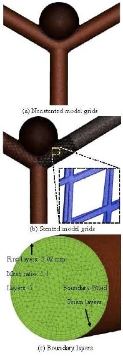
Fig.2 Mesh information
1.5Boundary conditions and calculations
The wall elasticity of the cerebral artery is small compared to the large aorta[17], therefore, the rigid wall with no-slip condition is assumed in this simulation for simplicity. The physiological blood velocity waveform is obtained at the basilar inlet using Doppler ultrasound flow measurements, from a patient. Figure 3 shows the inlet velocity waveform. A zero pressure gradient at the outlets is chosen as the boundary conditions for two outlets of the LPCA and the RPCA.
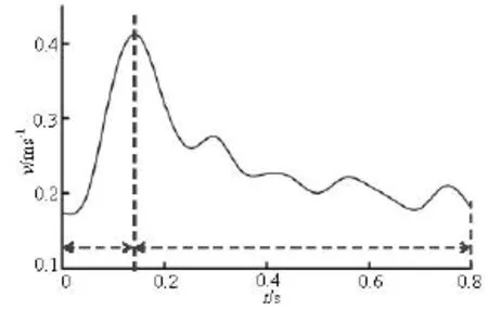
Fig.3 Physiological waveform of inlet velocity
The flow simulations are conducted by using the commercial CFD package ANSYS Fluent 12.0 (ANSYS Inc., USA). Three consecutive cardiac cycles are simulated to acquire stable and precise periodic results, and the results of the last cycle are presented. In the simulation, the semi-implicit (SIMPLE) method is chosen to solve Eqs.(1) and (2), the time step is set to 10–5seconds to reduce the Courant number. The convergence criteria are set to 10–5times the residual for each time step. The computations are performed on a 64 GB RAM memory, double Intel Xeon CPU (2.96 GHz, 12 cores) workstation in windows 7 64-bit operation system.
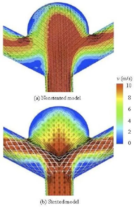
Fig.4 Velocity distribution on the cross-section for non-stented and stented models
2. Results
Results show distinct variations in the hemodynamic characteristics between the non-stented and stented models. The EL values of both non-stented and stented models in a cardiac cycle are shown in Table 1. The maximum EL of the non-stented model reaches its highest level at the peak systolic phase, equal approximately to 1.26 mw. When the stent is implanted into the artery, the value of EL reaches its highest level at the same phase, of about 0.78 mw.
Figure 4 shows the velocity magnitude distributions at the peak systole for non-stented and stented models, respectively. The velocity distribution is on the cross-section of the aneurysm middle plan as shown in Fig.1(c). In the non-stented model, the blood directly flows into the aneurysm at a high speed and strongly impinges onto the dome wall of the aneurysm. Besides, the high speed region occupies almost 75% of the cross-section area. From the velocity vector plot, the flow pattern, the backflow, the vortices and the second flow can be observed in the aneurysm. For the stented model, the stent wires impede the blood flowing directly into the aneurysm and diffuse the blood flow into the PCA, which greatly reduces the magnitude of the impact force and the blood flow velocity in the aneurysm as compared with the non-stented model. As a result, the high speed zone is decreased by 40% in the aneurysm. In addition, the complex flow phenomena, like the vortices and the second flow are overally dampened by the stent deployment.
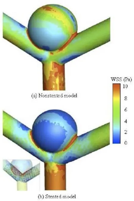
Fig.5 WSS distribution for non-stented and stented models
Figure 5 illustrates the distribution of the WSS for the non-stented and the stented models at the peak systole in a cardiac cycle. For the non-stented model, a high-velocity concentrated inflow impacts on the wall of the aneurysm to produce a relatively high WSS at the dome, of approximately 8 Pa. When the stent is placed across the neck of the aneurysm, the inflow is disrupted with a significant alteration in the intra-aneurysm hemodynamic characteristics. The WSS in the aneurysm is markedly reduced, and a relatively high WSS region can be found at the same impacted zone. It is shown that the stent greatly affects the WSS distribution on the aneurysm wall, while the influence on the other vessel areas is quite small. These findings are in good agreement with previous studies[21], as shown in Fig.6. The maximum WSS values of the two models are found at the neck of the aneurysm, and they are about 10 Pa. When the stent is implanted in the artery, the change of the WSS distribution pattern is quite small, while the WSS value on the aneurysm wall is reduced significantly. The WSS value of the stented model is about 43% lower than that of the non-stented model. This phenomena may be explained by the fact that the stent wires impede the blood flowing into the aneurysm and decrease a great deal of the flow impingement and the WSS. The value of the WSS is significantly confined, as shown in Fig.5.
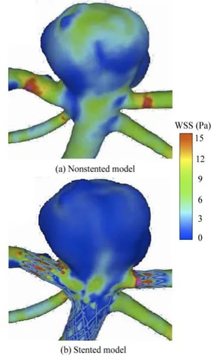
Fig.6 WSS distribution for non-stented and stented models (Sunil’s results)
The distribution of the pressure in the aneurysm of the non-stented and stented models is shown in Fig.7. In the non-stented model, there is a region of relatively high pressure at the dome of the aneurysm, of approximately 11 KPa, where is also the inflow impact region. The high pressure at the dome of the aneurysm may result in the expansion of the local aneurysm wall and the increase of the tensile stress, which might lead to the rupture of the aneurysm[5]. When the stent is implanted into the vessel, the impact force on the aneurysm dome is decreased. The high pressure region almost vanishes, with a small region at the dome of the aneurysm: the magnitude of the pressure is approximately 7.8 KPa. These results are consistent with those by Liou et al.[13].
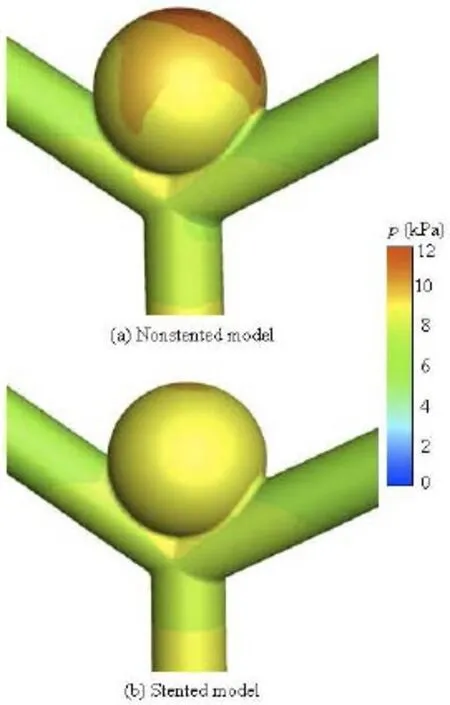
Fig.7 Pressure distribution for non-stented and stented models
3. Discussions
The aim of this paper is to study the treatment effect of the HPM stent on the cerebral aneurysm. In order to obtain a comprehensive understanding of the performance of the HPM stent, the CFD technique is applied to simulate the hemodynamic characteristics of both non-stented and stented models. Simulation results show that the hemodynamic characteristics are significantly changed when the stent is implanted in the IBTA model. To better illustrate the treatment effect of the stent, several hemodynamic indices such as the EL, the blood flow pattern, the flow velocity, the WSS and the pressure are analyzed in this study.
Simulation results show that the hemodynamic indices of the stented model are quite different from those of the non-stented model. The EL is decreased to 0.78 mw when the stent is implanted into the model. That means that the stent forces the fluid to directly flow into LPCA and RPCA, which leads to less energy loss than the non-stented model and this flow state will provide more energy to the downstream artery.
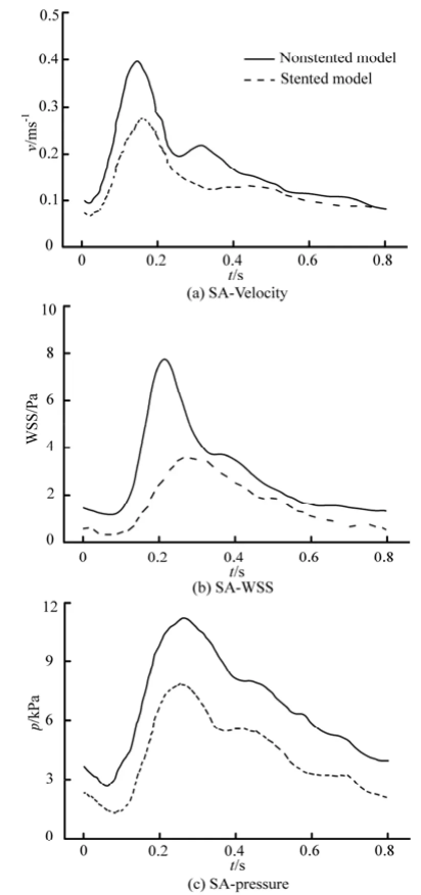
Fig.8 Spatially Averaged (SA) indices in the aneurysm region during a cardiac cycle
On the other hand, the velocity in the stented aneurysm model is significantly decreased in a cardiac cycle, which would increase the possibility of the intra-aneurysm thrombus formation and thereby strengthens the wall of the aneurysm[13-15]. The stent wires impede the blood directly flowing into the aneurysm, which would obviously reduce the magnitude of theimpact force on the dome of the aneurysm. Additionally, the complex flow structures in the aneurysm such as the backflow, the secondary flow, are dampened by the stent deployment. In a cardiac cycle, the averaged velocity profile is shown in Fig.8(a).
Furthermore, the WSS is also calculated in the present study, as shown in Fig.5. In both non-stented and stented models, the maximum value of the WSS is at the dome of the aneurysm region. The WSS strongly affects the vessel Endothelial Cell (EC) function. Studies show that if the WSS is increased locally, it could potentially cause a local enlargement of the artery, which is called the destructive remodeling, induced by excessive production of Nitric Oxide (NO)[22]. In addition, the high WSS may cause damage to the endothelial cells of the artery, and weaken the structure of this region[6,22,23]. In the non-stented model, the EC is related with a large WSS, the amount of NO secreted is increased significantly, leading to an inhibition of the EC growth, which consequently inhibits the thrombus formation. When the stent is placed into the vessel, the WSS at the dome of the stented aneurysm is decreased due to the reduction of the velocity in the vicinity of the aneurysm orifice. In a cardiac cycle, the WSS of the stented model is markedly reduced as compared to the non-stented model. This state will provide a more thrombogenic chance inside the aneurysm. The averaged WSS profile is shown in Fig.8(b). These findings are consistent to those reported by Liou et al.[13], where it is suggested that the stent operation will decrease the magnitude of the WSS, and reduce the risk of the aneurysm rupture.
Additionally, the pressure distributions of the two models are analyzed. When the stent is implanted, the high pressure region in the dome of the aneurysm vanishes, and the wall pressure distribution of the aneurysm becomes uniform. The balanced pressure distribution signifies a smaller pressure gradient in the aneurysm, which induces a lower surface tension of the aneurysm wall, and therefore decreases the risk of the aneurysm rupture. The averaged pressure profile is shown in Fig.8(c). It is shown that, in a cardiac cycle, the pressure of the stented model is decreased by about 40% as compared to the non-stented model. Similar results were reported by Liou et al.[13], where it is shown that the high pressure at the dome of the aneurysm is markedly decreased and balanced when the stent is implanted into the vessel.
There are some limitations in our study. Firstly, only an idealized simplified aneurismal model is considered in our simulation. More patient-specific case should be investigated in the future in order to reach quantitative and accurate conclusions and provide specific suggestions to the neurosurgeons. Secondly, the non-Newtonian blood properties and the compliance of the aneurismal wall are very irregular. The Newtonian fluid and the rigid arterial boundary conditions are assumed in the present studies. These assumptions could result in some over-estimation of the blood flow velocities and the WSS distributions.
在当前的新媒体环境下,高校学生在知识获取方面,已经不会受到时间和空间的限制了,其和社会相接触的机会也开始大大增加,但由于学生的心理认识还不够成熟,在实际交流过程中极容易受到诱导。学生在实际学习过程中,能够直接利用网络来发表自身意见和观点,但由于现如今网络信息的质量就存在良莠不齐的问题,很多学生会在不经意之间接触到各种不良、不实的负面信息,并对学生产生负面影响[1]。同时,很多大学生出现过于沉迷网络世界的情况,其在现实生活中会有众多的不如意等,就开始逐渐依赖于网络沟通,导致现实情感沟通的比例也开始越来越小,从而形成一个恶性循环。
In the further study, the underlying compliance of the artery should be taken into account in simulations. The validation of the numerical results by measurements of PIV will be carried out throughin vitroflow loop tests on three-dimensional plexiglass aneurismal models.
4. Conclusions
This paper investigates the stent influence on the hemodynamic characteristics in the BTA. The following conclusions can be drawn: when applying the stent to treat the aneurysm, the wires of the stent impede the blood flow into the aneurysm sac, which would significantly reduce the magnitude of the impact force of the blood flow, the pressure and the WSS at the dome of the aneurysm wall. The flow velocity in the aneurysm sac is also greatly reduced. Under this flow condition, the potential risk of the aneurysm enlargement and rupture is reduced, with an expected treatment effect.
The simulation results not only provide a valuable reference for optimizing the stent design, but also help neurosurgeons to select suitable stents and to establish reasonable operation procedures.
[1] KREX D., SCHACKERT H. K. and SCHACKERT G. Genesis of cerebral aneurysms-an update[J].Acta Neurochir,2001, 143(5): 429-449.
[2] JUVELA S., POUSSA K. and PORRAS M. Factors affecting formation and growth of intracranial aneurysms: A long term follow up study[J].Stroke,2001, 32(2): 485-491.
[3] Van GIJN J., RINKEL G. J. E. Subarachnoid haemorrhage: Diagnosis, causes and management[J].Brain,2001, 124: 249-278.
[4] LARRABIDE L., KIM M. and AUGSBURGER L. et al. Fast virtual deployment of self-expandable stents: Method and in vitro evaluation for intracranial aneurysmal stenting[J].Medical Image Analysics,2012, 16(3): 721-730.
[5] BABIKER M. H., GONZALEA L. F. and ALBUQUERQUE F. et al. Quantitative effects of coil packing density on cerebral aneurysm fluid dynamics: An in vitro steady flow study[J].Annals of Biomedical Engineering,2010, 38(7): 2293-2301.
[6] RADAELLI A. G., AUGSBURGER L. and CEBRAL J. R. et al. Reproducibility of haemodynamical simulations in a subject-specific stented aneurysm model-A report on the virtual intracranial stenting challenge 2007[J].Journal of Biomechanics,2008, 41(10): 2069-2081.
[7] KIM M., TAULBEE D. B. and TREMMEL M. et al. Comparison of two stents in modifying cerebral aneurysm hemodynamics[J].Annals Biomedical Engineering,2008, 36(5): 726-741.
[8] APPANABOYINA S., MUT F. and LÖHNER R. et al. Computational fluid dynamics of stented intracranial aneurysms using adaptive embedded unstructured grids[J].International Journal for Numerical Methods in Fluids,2007, 57(5): 475-493.
[9] LYLYK P., FERRARIO A. and PASBON B. Experience with the neuroform self-expanding stent for the treatment of intracranial aneurysms[J].Neurosurgery,2005, 102 (2): 235-241.
[10] BARATH K., CASSOT F. and FASEL J. H. Influence of stent properties on the alteration of cerebral intraaneurysmal hemodynamics: Flow quantification in elastic sidewall aneurysm models[J].Neurological Research,2005, 27(Suppl. 1): 120-128.
[11] LIEBER B. B., GOUNIS M. J. The physics of endoluminal stenting in the treatment of cerebrovascular aneurysms[J].Neurological Research,2002, 24(Suppl. 1): 33-42.
[12] MORRIOS L., DELASSUS P. and WALSH M. A mathematical model to predict the in vivo pulsatile drag forces acting on bifurcated stent grafts used in endovascular treatment of abdominal aortic aneurysms (AAA)[J].Journal of Biomechanics,2004, 37(7): 1087-1095.
[13] LIOU T. M., LIOU S. N. and CHU K. L. Intra-aneurysmal flows with helix and mesh stent placement across side-wall aneurysm pore of a straight parent vessel[J].Journal of Biomechanical Engineering,2004, 126(1): 36-43.
[14] MORI F., MATSUZAWA T. Study on flow in stent neighborhood and hemodynamics in cerebral aneurysm[C].6th World Congress of Biomechanics.Singapore, 2010, 31: 465-468.
[15] HIRABAYASHI M., OHTA M. and BARÁTH M. et al. Numerical analysis of the flow pattern in stented aneurysms and its relation to velocity reduction and stent efficiency[J].Mathematics and Computers in simulation,2006, 72(2-6): 128-133.
[16] SZIKORA I., PAAL G. and UGRON A. et al. Impact of aneurysmal geometry on intraaneurysmal flow: A computerized flow simulation study[J].Neuroradiology,2008, 50(5): 411-421.
[17] WANG Qing, WANG Wei-zhe and FEI Zhi-min et al.. Simulation of blood flow in intracranial ICA-PComA aneurysm via computational fluid dynamics modeling[J].Journal of Hydrodynamics,2009, 21(5): 583-590.
[18] AUGSBURGER L., FARHAT M. and REYMOND P. et al. Effect of flow diverter porosity on intraaneurysm blood flow[J].Clincal Neurordiology,2009, 19(3): 204-214.
[19] SUN Q., WAN D. W. and LIU J. F. et al. Patient-specific computational fluid dynamic simulation of a bilateral bidirectional Glenn connection[J].Medical Biologival Engineering Computing,2008, 46(11): 1153-1159.
[20] LIU J. L., QIAN Y. and ITATANI K. Image-based computational hemodynamics of distal aortic arch recoarctation following the Norwood procedure[C].4th International Conference on Biomedical Engineering and Informatics, IEEE 2011.Shanghai, China, 2011.
[21] APPANABOYINA S., MUT F. and LÖHNER R. et al. Simulation of intracranial aneurysm stenting: Techniques and challenges[J].Computer Methods Applied Mechanics Engineering,2009, 198(45-46): 3567-3582.
[22] SFORZA D. M., PATMAN C. M. and CEBRAL J. R. Hemodynamics of cerebral aneurysms[J].Annual Review Fluid Mechanics,2009, 41: 91-107.
[23] LIOU T. M., LI Y. C. Effects of stent porosity on hemodynamics in a sidewall aneurysm model[J].Journal of Biomechanics,2008, 41(6): 1174-1183.
10.1016/S1001-6058(13)60432-1
* Project supported by the Science and Technology Committee of Shanghai Municipality (Grant No. 08JC1411200), the Chinese Medical Association Program (Grant No. 09010200175).
Biography: QIU Xiao-ning (1982-), Male, Ph. D. Candidate
FEI Zhi-min,
E-mail: tommyfei@126.com
猜你喜欢
房地产导刊(2022年10期)2022-10-18 08:03:52
现代企业(2021年2期)2021-07-20 07:57:44
湖南工业职业技术学院学报(2021年1期)2021-04-13 01:33:56
甘肃教育(2020年21期)2020-04-13 08:08:48
活力(2019年19期)2020-01-06 07:37:16
时代青年·视点(2018年1期)2018-03-26 06:06:14
学周刊(2016年23期)2016-09-08 08:57:48
潍坊学院学报(2016年6期)2016-04-18 13:57:06
文学教育(2016年18期)2016-02-28 02:34:53
湖南城市学院学报(自然科学版)(2016年4期)2016-02-27 14:02:46

- 水动力学研究与进展 B辑的其它文章
- Simplified hydrodynamic models for the analysis of marine propellers in a wake-field*
- Analysis of shear rate effects on drag reduction in turbulent channel flow with superhydrophobic wall*
- Numerical study of flow fluctuation attenuation performance of a surge tank*
- A three-dimensional hydroelasticity theory for ship structures in acoustic field of shallow sea*
- Experimental study by PIV of swirling flow induced by trapezoid-winglets*
- The calculation of mechanical energy loss for incompressible steady pipe flow of homogeneous fluid*