
A three-dimensional hydroelasticity theory for ship structures in acoustic field of shallow sea*
2013-06-01 12:29:59ZOUMingsong邹明松WUYousheng吴有生LIUYanmin刘艳敏LINChanggang林长刚ChinaShipScientificResearchCenterWuxi214082Chinamailzoumingsaliyuncom
水动力学研究与进展 B辑 2013年6期
ZOU Ming-song (邹明松), WU You-sheng (吴有生), LIU Yan-min (刘艳敏), LIN Chang-gang (林长刚) China Ship Scientific Research Center, Wuxi 214082, China, E-mail: zoumings@aliyun.com
A three-dimensional hydroelasticity theory for ship structures in acoustic field of shallow sea*
ZOU Ming-song (邹明松), WU You-sheng (吴有生), LIU Yan-min (刘艳敏), LIN Chang-gang (林长刚) China Ship Scientific Research Center, Wuxi 214082, China, E-mail: zoumings@aliyun.com
(Received August 12, 2013, Revised November 6, 2013)
Nowadays the development of green ship technology requires the vibration and noise control of oceangoing ships. The three-dimensional hydroelasticity theory of ships was previously extended to include the effect of fluid compressibility. This enables the dynamic responses and the acoustic radiations of a ship excited by onboard machineries or fluid fluctuation loads to be predicted. In this paper the hydroelastic analysis and sonoelastic analysis methods are further incorporated with the Green’s function in the Pekeris ocean hydro-acoustic waveguide model to work out a three-dimensional sonoelastic analysis method for ships in the ocean hydro-acoustic environment. As examples, the sound radiations of a floating elastic spherical shell excited by a concentrated force and a traveling LNG ship excited by the propeller induced pulsating forces acting on the wetted bottom plate of the stern in the shallow sea environment are predicted. The influences of the free surface and the sea bed on the generalized hydrodynamic coefficients and the acoustic pressure distributions in fluid domain are illustrated and discussed.
hydroelasticity, sonoelasticity, acoustic waves, shallow sea environment, LNG ship
Introduction
Acoustic vibrations of ship structures and transmissions of acoustic waves in ocean environment are two important problems, especially when the “green ship” concept has attracted great attention in shipbuilding and ocean transportation industries nowadays. A large portion of research works about the sound radiation of vibrating structures in the sea have assumed that the surrounding fluid domain is homogeneous and unbounded. Zou et al.[1-4]extended the three-dimensional hydroelasticity theory of ships[5-8]to include the effect of fluid compressibility by replacing the Green’s function for incompressible fluid with that for uniformly distributed ideal compressible fluid in semiinfinite domain. This enables the acoustic responses and radiations of ship structures to be predicted with the free surface and the forward speed effects being included. If the fluid domain is not semi-infinite, in shallow sea for example, the acoustic behavior of the seabed medium has to be considered. It is a common practice in ocean acoustics that the effects of boundaries and the fluid field heterogeneity are included in the description of the general ocean-acoustic propagation scenario, yet with some simplifications[9-12]. In reality, the effects of sound radiations of vibrating structures are closely related to the surrounding waveguide environment[13]. The sea surface may usually be treated as a pressure-release boundary[14]. The sea bottom can be described by the pressure-release boundary, the penetrable boundary or the rigid boundary, etc., depending on the practical situations[9]. It is therefore necessary and possible to combine the existing three-dimensional sonoelastic analysis method[1,2]with a suitable waveguide environment model to develop an approach to the prediction of ship acoustics in shallow sea. This will be briefly described in this paper. The sonoelastic analysis method is further incorporated with the Green’s function in the Pekeris ocean hydro-acoustic waveguide model[9]. The seabed condition is then represented by a penetrable boundary with prescribed density and sound speed. A three-dimensional sonoelasticity theory of ships in shallow sea hydro-acoustic environment is put together forward with the corresponding numerical method.
Numerical examples of acoustic radiations of a half-submerged spherical shell excited by a concentrated force and a traveling LNG ship excited by the propeller-produced hydrodynamic pulsating forces, bothin the Pekeris shallow sea waveguide environment, are presented. The influences of free surface and sea bed on the generalized hydrodynamic coefficients are examined, and the acoustic pressure distributions are given.
1. Boundary integral equation of acoustic waves
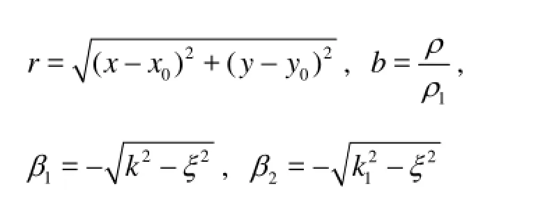
In this paper the acoustic vibrations and sound radiations of a ship are studied in an equilibrium coordinate systemOxyz, with thex-axis pointing from stern to bow, and thez-axis pointing upwards and passing through the equilibrium position of the gravity center of the ship.
It is assumed that the spatial distribution of fluid density is uniform in an inviscid, irrotational fluid flow field and the amplitudes of acoustic waves are small, and the acoustic-field velocity potentialφexists and satisfies the following equation in frequency domain

where =/kcωis the wave number,ωandcare the wave frequency and the wave speed respectively. In the case that the acoustic waves in the fluid field are induced by vibrations of a submerged or floating structure whose mean wetted surface is represented byS, the scalar quantityφin whole fluid field can be completely described by its distribution onSin terms of the Green equation or the simple source boundary integral equation as follows[1,2]
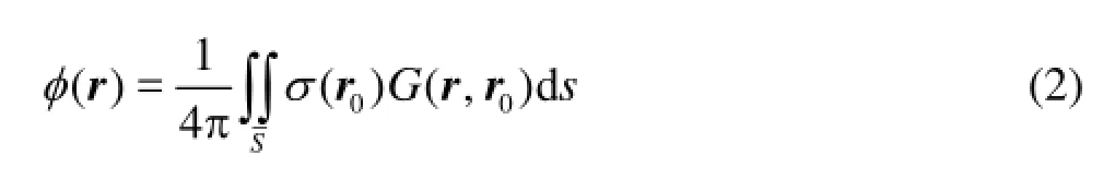
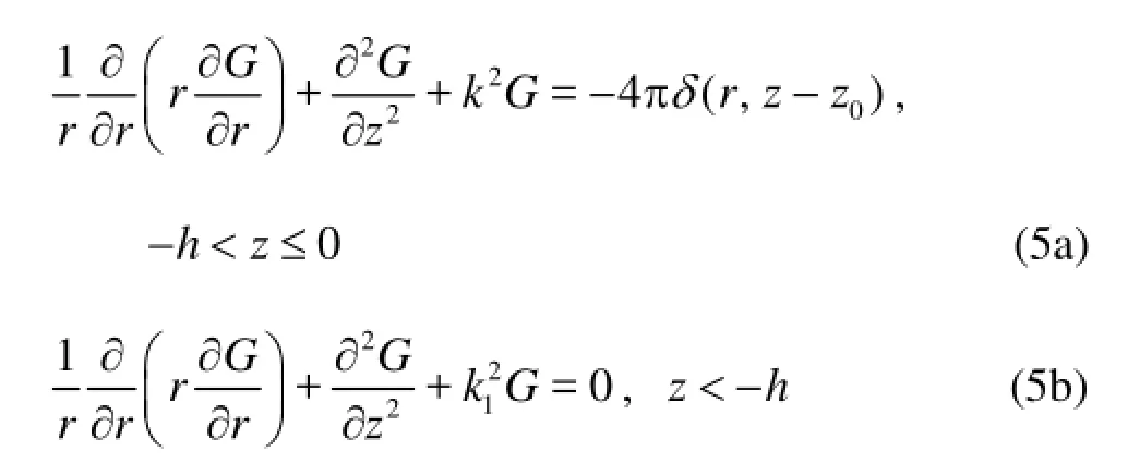
whereσ(r0),r=(x,y,z)andr0=(x0,y0,z0)are respectively the source strength, the field point and the source point on the wetted surface of the body,G(r,r0) is the acoustic Green’s function, which is a solution to the inhomogeneous Helmholtz equation for waves of simple harmonic time dependence, and satisfies the free surface and the sea bed boundary conditions
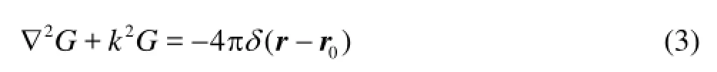
whereδ(r-r0) is the three-dimensional Dirac delta function. This Green’s function represents the hydroacoustic field produced by a point source atr. Equation (2) shows that the acoustic field is a composition of the fields produced by a series of point sources of different strengths.
2. Pekeris waveguide green’s function
In different ocean environments the transmissions of the acoustic waves produced by a point source are quite different. Many acoustic waveguide models and the corresponding computational methods have been developed to describe the sound propagation in different ocean environments, for example the deep water, the shallow water, the horizontally stratified water and the range-dependent environment, etc.[9].

Fig.1 The Pekeris waveguide with pressure-release surface and penetrable seabed
In this paper the Pekeris shallow sea waveguide model as shown in Fig.1 is employed to describe the ocean acoustic environments in the three-dimensional sonoelastic analysis. The Pekeris waveguide assumes that the free surface is a plane pressure-release boundary of the sea water, which has the densityρand sound speedc, the seabed is a plane penetrable boundary represented by an infinite fluid halfspace with the density 1ρand sound speed1c. In the following analyses four different ocean environments listed in Table 1 are used.
The Pekeris waveguide Green’s function is in the form:
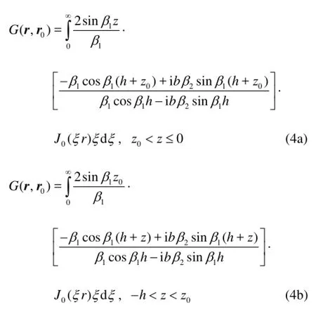
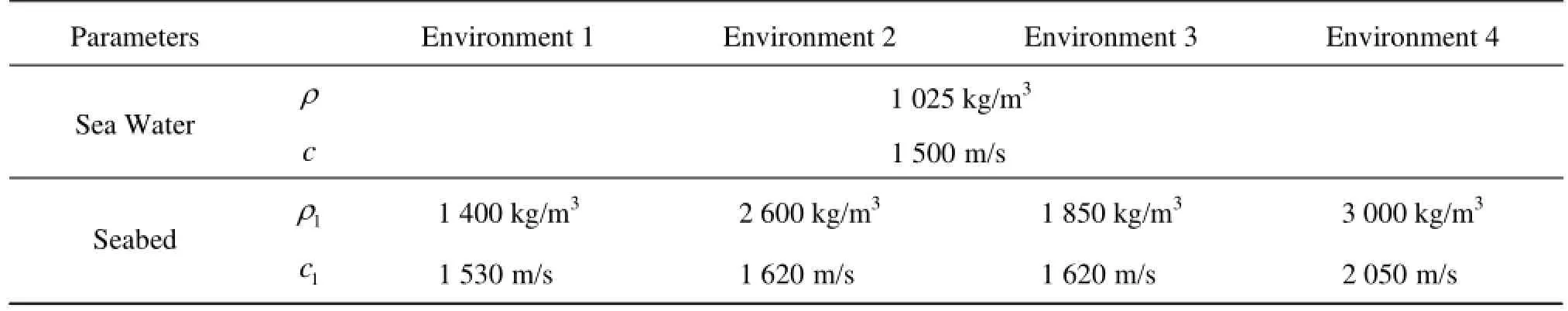
Table 1 Parameters of the shallow sea environment

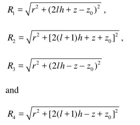
where At the seabed an incident plane sound wave with reflection and refraction is shown in Fig.2. According to Brekhovskikh’s theroy the reflection coefficient on the seabed can be represented as
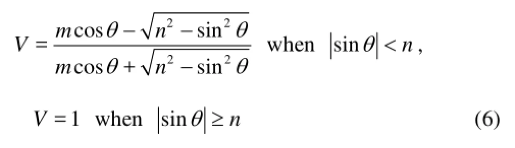
wherem=ρ1/ρ,n=c/c1≤1. HereV=1 indicates the perfect reflection. Figure 2 also shows the variations of the reflection coefficients with the incidence angler. The seabed parameters are the “Environments 1 and 2” listed in Table 1. At the incidence angle between 0o-50o, the reflection coefficients are almost
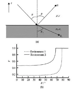
Fig.2 Reflection-refraction of plane sound wave on the seabed and the reflection coefficients

Fig.3 The chain of virtual sources representing the multiple-reflections between the sea surface and the seabed
constant. In the case of normal incidence =θ0o, the reflection coefficients are about 0.1-0.6 for different seabed parameters. When a point source at (x0,y0,z0) radiates acoustic wave which reaches the seabed and reflects to a field point (,,)xyzwith the incidenceangler smaller. Than 50o, namelyr/(2h+z0+z)<1.19, the reflection coefficient is approximately constant. Owing to multi-reflections between the free surface and the seabed, the acoustic waves generated by this point source are equivalent to the actions of a chain of virtual point sources shown in Fig.3. A simplified form of Green’s function and also the approximation of Eq.(4) in the spatial regionr/(2h+z0+z)<1.19 may then be described as
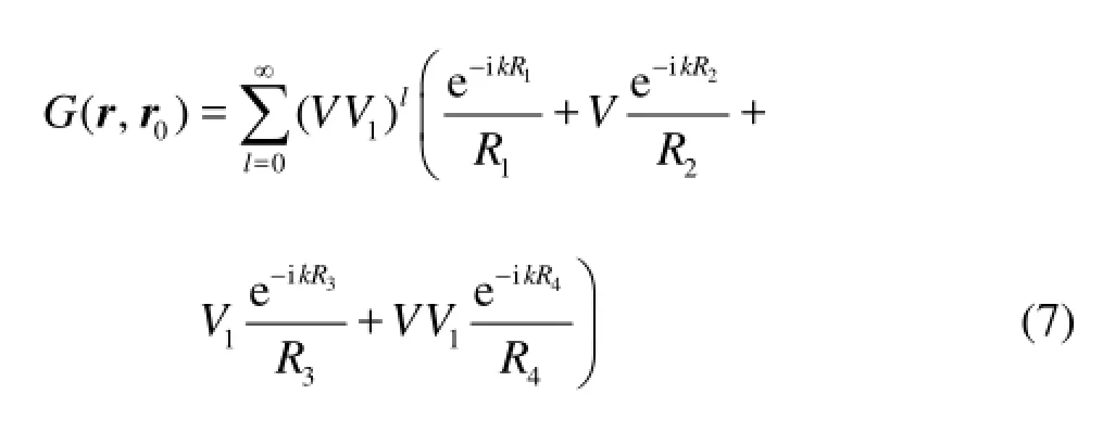
whereVand1Vare respectively the reflection coefficients of the seabed and the free surface. For a pressure-release boundary,1=V–1.
It is found that whenV≈0.1-0.6, taking only the first 7 terms of Eq.(7) would be enough for convergence.
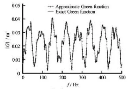
Fig.4 Verification of the approximate Green’s function
As an example, the Green’s functions for a pair of source and field points at0=z–30 m and0=z–25 m with the horizontal distance =r50 m were calculated by both Eq.(4) and Eq.(7) in the shallow sea environment of depth =h65 m and parameters of“Environment 3”. The comparison of the results is shown in Fig.4. Evidently, sincer/(2h+z0+z)= 0.666<1.19 the approximate solution of Eq.(7) coincides with the exact solution of Eq.(4).
3. Sono-elastic analysis method of ships in shallow sea
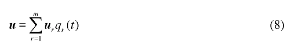
Replacing the Green’s function for incompressible fluid in the three-dimensional hydroelasticity theory[5]with the Pekeris waveguide Green’s functions represented by Eqs.(4) or (7), a sonoelastic analysis method is developed. It enables the structural vibrations and sound radiations of a ship in shallow sea to be predicted, where the ocean environment could be considered in a more practical way. Besides the Green’s function all the equations and expressions are the same as presented in Refs.[1-3]. By introducing the principal coordinatesqr(t) (r=1,2,…,m), the displacementu=(u,v,w)of the vibrating structure is expressed as the superposition of the principal modesur=(ur,vr,wr), (r=1,2,…,m) of the structure in vacuum The acoustic pressure in the fluid domain radiated by the vibrating structure is
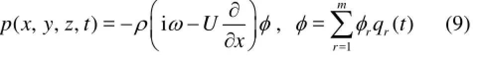
whereφr(x,y,z) is the radiation potential corresponding to ther-th principal mode, which satisfies the interface boundary condition
In this equationUis the forward speed of the ship,n=(n1,n2,n3)is the outward unit normal vector of the wetted surface, andθr=(θr1,θr2,θr3)=∇×θr/2 is the principal rotation vector.
The generalized equations of motion may be represented in terms ofqr(t) in the matrix form

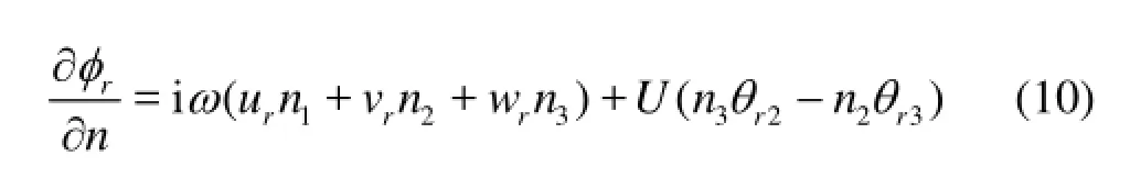
where [a], [b] and [c] are matrices of generalized
modal inertial, modal damping and modal stiffness of the dry structure respectively, {q} and {Ξ} are the principal coordinates vector and the generalized force vector respectively, [A], [B] and [C] are the matrices of generalized hydrodynamic inertia, damping and restoring coefficients respectively:
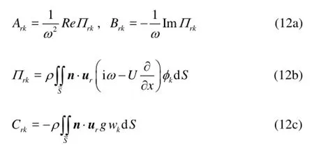
The sound power radiated by the ship hull may be calculated by a surface integration of the acoustic pressure multiplied by the structural normal velocity over the wetted surfaceS. Hence it is found from Eqs.(8), (9) and (12) that the total radiated sound power may be directly calculated in terms of the products of the hydrodynamic coefficients and the principal coordinates. In potential calculations the Green’s functions of Eqs.(4) and (7) are used respectively outside or inside the region ofr/(2h+z0+z)<1.19. To verify the numerical methods, the hydrodynamic added mass of a rigid sphere of radius =R0.5 m, half submerged in shallow water of different depthhas shown in Fig.5 is calculated. In case the water is incompressible, the seabed is rigid and the surface waves are ignored, an analytical solution of the heave added mass is given as[15]
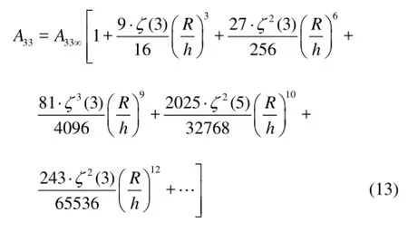
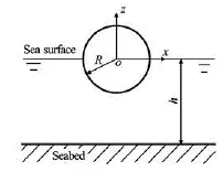
Fig.5 A rigid sphere half submerged in water of finite depth
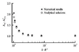
Fig.6 Verification of the numerical method by comparison of the heave added mass of a rigid sphere in water of finite depthh
4. Sound radiation of a spherical shell in shallow sea environment
The sound radiation of a spherical shell half-submerged in water is investigated. The coordinate system is the same as in Fig.5. A unit concentrated sinusoidal excitation force of frequency 400 Hz acts vertically downward at the bottom of the shell (=)zR-. The radius, thickness, material density, Young’s modulus and Poisson’s ratio of the shell are respectively 0.5 m, 0.001 m, 7 800 kg/m3, 2.1×10¹¹N/m2and 0.3. The damping ratios of the dry modes are assumed to be 0.01. The parameters of the fluid and seabed conditions are defined by the “Environment 4” in Table 1.
Figures 7(a)-7(c) exhibit the contours of the sound source pressure, i.e., the pressure amplitude multiplied by the distance between the observation point and the spherical shell center. This indicates that if the noise radiation property of the shell is observed at any position by converting the measured pressure to that at the position 1 m to the shell center, the description will be quite different, depending on the observation position and the water depth. It also shows thatthe seabed boundary greatly influences the radiation sound field.
Fig.7 Distribution of the sound source pressure of the spherical shell excited by a unit concentrated force of frequency 400 Hz in shallow water
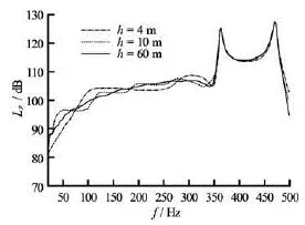
Fig.8 The source sound level of the spherical shell in water with different depth
Once the sound power generated by the wetted surface of the structure is calculated, the source sound pressure may be evaluated, which is equivalent to the pressure uniformly distributed over an imaginary semi-spherical surface of radius 1 m to the sound center, and in total generate the same sound power. The frequency variations of thus obtained source sound levelsLpof the shell with reference pressurepo= 1 μPa for different water depths are shown in Fig.8. Obviously in shallow sea the source sound level changes with the water depth due to the seabed absorption and the interference of reflection waves, especially in low frequency regions.
5. Radiation noise assessment of a large LNG ship
The influences of noise radiated by ocean-going ships on living marine resources have attracted great attention nowadays. It was reported that the noise of frequencies lower than 100 Hz is particularly harmful to marine fishes by altering their life habits, reproduction and survival abilities. The four major noise sources of a large surface ship are respectively the propeller born noise, the flow induced noise, the structural noise generated by propeller and the mechanical excitations. A large portion of energy radiated by the later two sources is in the frequency range below 100 Hz. The method described in this paper provides a useful tool to predict and assess these two kinds of low-frequency noise.
As an example of applications, the structural radiation noise of a membrane-type LNG ship excited by the propeller-generated fluctuation pressure is predicted. The ship is of length =L292 m, breadth 43.35 m, depth 26.25 m, draught 11 m, maximum speed 19.5 kn and storage 147 km3. The parameters of the fluid and seabed conditions are described by the“Environment 4” listed in Table 1.
5.1Dry modes and hydrodynamic added mass
The principal dry modes of the LNG ship in vacuum were obtained by finite element analysis. The model is represented by 46 004 elements including 22 734 plate elements and 21 649 beam elements as shown in Fig.9.
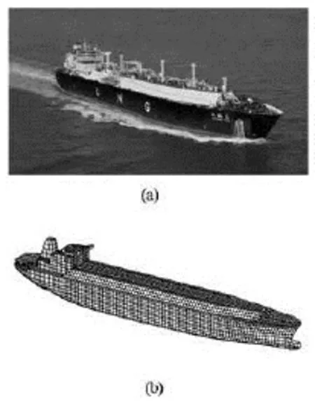
Fig.9 A LNG ship and its 3-D FEM model
The variations with water depths and frequencies of the predicted added-mass 77Aand 1010Aof the first and the second vertical bending modes are exhibitedin Figs.10 and 11. It shows in Fig.10 that at a very low frequency 0.01 Hz with the wavelength far greater than the water depth and the ship dimension, the fluid compressibility may be ignored, and the added-mass coefficients become constant for water depth larger than 4-5 times of the ship draught. At a higher frequency 15 Hz, the effects of fluid compressibility and reflection-wave interferences make the added-mass coefficients vary with the water depth until it is deeper than 10 times of the ship draught.
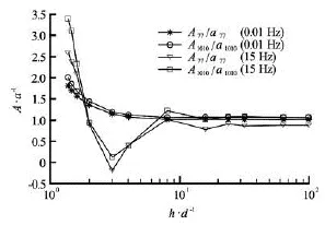
Fig.10 Variations of the added-mass coefficients with water depth at low and high frequencies
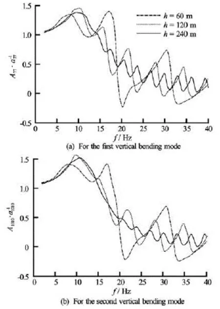
Fig.11 Variations of the added-mass coefficients with frequency in different water depths
Due to the interference of multi-reflection waves between the water surface and the seabed, the curves of added-mass coefficients fluctuate with regard to frequencies as shown in Fig.11. The frequency differences between the two adjacent peaks of the addedmass curves for water depths 60 m, 120 m and 240 m, are respectively 13.4 Hz, 6.4 Hz and 3.1 Hz. It is noticed that waves of these frequencies have half wave lengths exactly equal to the corresponding water depths. Affected by the seabed, the added mass for water depth =h60 m has negative values at some frequencies.
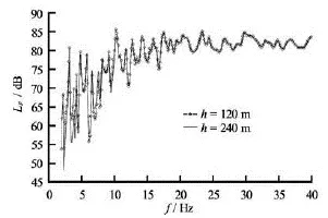
Fig.12 Transfer functions of the source power level of radiation noise excited by a unit pulsating force for different water depths (Reference pressure 1 μPa)
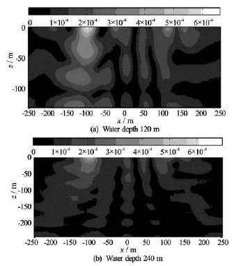
Fig.13 Distributions of the sound pressure radiated by the ship in different water depths under excitation of a unit pulsating force of frequency 22 Hz
5.2Radiation noise of the LNG ship excited by the propeller produced pulsating force
The transfer functions of radiation noise source levelpLof the LNG ship excited by the pulsating force of unit amplitude acting vertically at the stern wet-deck was calculated. In the water of depths 120 m and 240 m, both are deeper than 10 times of the shipdraught, the source levels are close to each other as shown in Fig.12. The distributions of the radiated sound pressure excited by a unit pulsating force of frequency 22 Hz are exhibited in Fig.13.
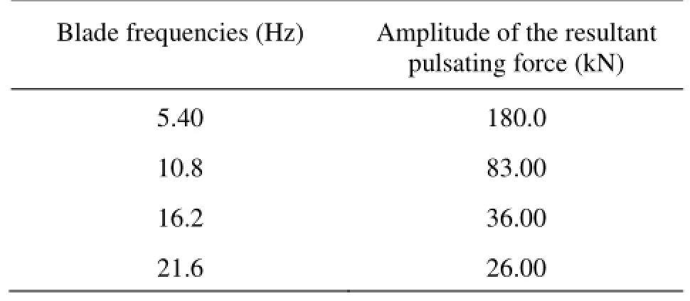
Table 2 The test results of rhe resultant pulsating of the ship at 19.5 kn
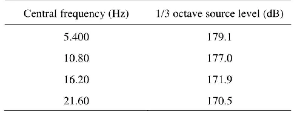
Table 3 The predicted radiation of the ship at 19.5 kn excited by the pulsating forces
The model test results of the propeller-produced pulsating forces are used to predict the propeller-excited radiation noise of the ship traveling at 19.5 kn. The propeller has 4 blades and diameter of 8.8 m. The amplitudes of resultant pulsating forces at the blade frequency 5.4 Hz and its 2nd to 4th harmonics are listed in Table 2. To form the excitation spectrum, these resultant pulsating forces were averagely distributed in the 1/3 octave bandwidths of which the blade frequency and its harmonic frequencies are the central frequencies. Multiplications of this excitation spectrum by the corresponding transfer functions provide the propeller-produced source level and the sound pressure field radiated by the ship. The predicted 1/3 octave source levels of the 4 bandwidths are listed in Table 3. The total sound level of radiation noise reaches as high as 182 dB.
6. Conclusions
Incorporating the three-dimensional hydroelasticity theory with the Pekeris shallow sea waveguide model of the ocean acoustic environment, a numerical method has been established to predict the fluid-structure interactions and sound radiations of a ship induced by propeller or mechanical excitations in compressible fluid with the free surface and the sea bed reflection effects being included.
The method and the code has been partly validated by comparing the predicted results and the analytical solutions of the hydrodynamic added mass coefficients of a half submerged rigid sphere in water of finite depth. The numerical examples of an elastic spherical shell and a LNG ship exhibit that the reflection and absorption effects of the seabed provide obvious influences on the fluid-structure interactions, the distribution and transmission of the radiated noise of a floating or submerged structure in shallow sea. The predicted results of the LNG ship show that in low frequency region where the fluid compressibility could be ignored the hydrodynamic coefficients keep constant as the water depth is greater than 4-5 times of the ship draught. However at higher frequencies the hydrodynamic coefficients fluctuate with frequencies due to the effects of wave interference and multi-reflections between the free surface and the seabed.
[1] ZOU Ming-song, WU You-sheng and SHEN Shun-gen et al. The three-dimensional hydroelasticity theory of ship structures in acoustic medium with the forward speed and the free surface effect[J].Journal of Ship Mechanics,2010, 14(11): 1304-1311(in Chinese).
[2] ZOU Ming-song, WU You-sheng and YE Yong-lin. Three-dimensional hydroelastic analysis of acoustic responses of ship structures[C].The 9th International Conference on Hydrodynamics.Shanghai, China, 2010, 844-851.
[3] ZOU Ming-song, WU You-sheng and YE Yong-lin et al. Three-dimensional sono-elasticity analysis of floating bodie[J].Journal of Ship Mechanics,2013, 17(3): 298-305.
[4] QI Li-bo, ZOU Ming-song. Acoustic radiation of stiffened cylinder with different shells[J].Journal of Ship Mechanics,2013, 17(6): 697-701.
[5] BISHOP R. E. D., PRICE W. G. and WU Y. A general
linear hydroelasticity theory of floating structures moving in a seaway[J].Philosophical Transactions of the Royal Society, London A,1986, 316(1538): 375-426.
[6] CHEN X. J., WU Y. S. and CUI W. C. et al. Review of hydroelasticity theories for global responses of marine structures[J].Ocean Engineering,2006, 33(3-4): 439-457.
[7] WU Y. S., CUI W. C. Advances in the three-dimensional hydroelasticity of ships[J].Proceedings of the Institution of Mechanical Engineers, Part M: Journal of Engineering for the Maritime Environment,2009, 223(3): 331-348.
[8] WU You-sheng, TIAN Chao and ZONG Zhi et al. Hydroelastic investigation on dynamic response of VLFS under wave environment near ocean island[C].Proceeding of the 25th National Conference on Hydrodynamics and 12th National Congress on
Hydrodynamics.Zhoushan, China, 2013, 1-13(in Chinese).
[9] JENSEN F. B., KUPERMAN W. A. and PORTER M. B. et al.Computational ocean acoustics[M]. Second Edition, New York, USA: Springer, 2011.
[10] FAWCETT J. A. Evaluation of integrals of target/seabed scattering using the method of complex images[J].Journal of the Acoustical Society of America,2003, 114(3): 1406-1415.
[11] LUCIFREDI I., SCHMIDT H. Subcritical scattering from buried elastic shells[J].Journal of the Acoustical Society of America,2006, 120(6): 3566-3583.
[12] ABAWI A. T., PORTER M. B. Propagation in an elastic wedge using the virtual source technique[J].Journal of the Acoustical Society of America,2007, 121(3): 1374-1382.
[13] ZOU Yuan-jie, ZHAO De-you. A vibro-acoustic study on structures in shallow water[J].Journal of Vibration Engineering,2004, 17(3): 269-274(in Chinese).
[14] LI Sheng, ZHAO De-you. Research on acoustic radiation in a three-dimensional half space[J].Journal of Ship Mechanics,2004, 8(1): 106-112(in Chinese).
[15] KOROTKIN A. I.Added masses of ship structures[M]. New York, USA: Springer, 2009.
10.1016/S1001-6058(13)60442-4
* Biography: ZOU Ming-song (1982-), Male, Ph. D. Candidate, Engineer

- 水动力学研究与进展 B辑的其它文章
- Simplified hydrodynamic models for the analysis of marine propellers in a wake-field*
- Analysis of shear rate effects on drag reduction in turbulent channel flow with superhydrophobic wall*
- Numerical study of flow fluctuation attenuation performance of a surge tank*
- Experimental study by PIV of swirling flow induced by trapezoid-winglets*
- The calculation of mechanical energy loss for incompressible steady pipe flow of homogeneous fluid*
- A preliminary study of the turbulence features of the tidal bore in the Qiantang River, China*