
Simplified hydrodynamic models for the analysis of marine propellers in a wake-field*
2013-06-01 12:29:59DURANTEDUBBIOSOTESTA
水动力学研究与进展 B辑 2013年6期
DURANTE D., DUBBIOSO G., TESTA C.
CNR-INSEAN, The Italian Ship Model Basin, Rome, Italy, E-mail: danilo.durante@cnr.it
Simplified hydrodynamic models for the analysis of marine propellers in a wake-field*
DURANTE D., DUBBIOSO G., TESTA C.
CNR-INSEAN, The Italian Ship Model Basin, Rome, Italy, E-mail: danilo.durante@cnr.it
(Received March 5, 2013, Revised August 8, 2013)
This paper presents a comparison among different hydrodynamic models for the analysis of the unsteady loads delivered by a marine propeller working in an axial, non-uniform inflow. Specifically, for a propeller subjected to a wake-field dominated by local high-frequency changes in space, the unsteady hydroloads predicted by the Nakatake formulation are compared with those given by the Theodorsen and Sears theories, respectively. Drawbacks and potentialities of these approaches are highlighted to assess a computationally efficient hydrodynamic solver for the analysis of operating conditions where propeller blades are significantly perturbed by a multi-harmonic onset-flow. Guidelines coming from this investigation may drive the choice of a fast and reliable unsteady propeller modeling that represents a good trade-off between accuracy of simulation and cost of computation within implementation in Computational Fluid Dynamics (CFD) solvers. The hydrodynamic formulations herein proposed are validated through numerical comparisons with the (accurate but computationally expensive) propeller loads predicted by a fully 3-D panel-method Boundary Element Method (BEM) solver, suited for the analysis of propellers operating in a complex hydrodynamic environment.
actuator disk, airfoil theories, Boundary Element Method (BEM) hydrodynamics
Introduction
During the last decade, Computational Fluid Dynamics (CFD) has been extensively used and validated for a broad set of marine hydrodynamic applications such as resistance, propulsion and maneuvering. From a theoretical standpoint, CFD simulations yield a detailed insight into the flow field around the stern, accounting for the hydrodynamic effects due to the propulsion system (propellers and shaft-line appendages) and complex interactions among hull, propeller and rudder. Although a key point for the success of the ship-design lies on stern hydrodynamic computations, CFD analysis of complete vessel configurations that include the bare-hull, appendages and propeller system is prohibitive in terms of computational demand because very fine time and spatial discretizations are required to well solve unsteady propeller hydrodynamics. Typically, the presence of propellers inside CFD equations is modeled through the actuator-disk approach where the momentum is transferred from the propeller into the fluid by means of a suitable system of body forces distributed into a disk of a finite thickness. The actuator-disk concept has been extensively applied and validated in the past for the prediction of resistance and propulsive-efficiency of different ship typologies and configurations[1], as well as for the analysis of propeller-rudder interaction[2]. Such an approach, inherently steady, is often used also to model propeller-induced effects in case of incoming flows whose features are far from those of the cruise ahead motion, yielding a quick prediction of the azimuthal propeller loads. In this context, for instance, Simonsen and Stern[3]proposed the Nakatake approach[4], based on the Yamazaki theory for screw propellers[5], as actuator-disk model to address the hydrodynamic analysis of steady maneuvers, whereas in Broglia et al.[6], the analysis of the turning circle maneuver was investigated by modeling the presence of propellers through the Hough and Ordway theory[7]and the Blade Element Momentum Theory approach[8], respectively. The momentum theory based approach might yield inaccurate predictions in off-design conditions and/or under the effects of rough sea since propeller blades might operate within a very complex onset-flow due to anticipated flow separation phenomena at sterncombined with massive vortical structures close to the propeller disk. In these circumstances the wake-field affecting propeller blades exhibits relevant spatial gradients that, in turns, yield an incoming flow with a significant harmonic content[9], therefore, the attempt of capturing unsteady propeller hydroloads through the actuator-disk theory might be inadequate. The above considerations have inspired the present work that proposes a numerical comparison among different hydrodynamic formulations for the prediction of the unsteady loads (thrust and torque) delivered by a marine propeller working in a non-uniform flow. Although a generic off-design condition involves the presence of an oblique flow, throughout the paper it is assumed that the propeller is perturbed by an axial, prescribed inflow characterized by local high-frequency changes in space. Without loss of generality, such an assumption allows the analysis of a propeller as it were in cruise motion (in hull-behind conditions), impinged by a wake-field with several harmonic components in its spectrum. Three hydrodynamic models, based on the potential theory for incompressible flows, are proposed and their drawbacks and potentialities are discussed. Aim of the work is to derive some guidelines for a further integration of these simplified propeller models within CFD solvers. In details, the hydrodynamic loads predicted by the Nakatake formulation[4]are compared with those evaluated through the Theodorsen and Sears unsteady sectional theories. In addition, a modified actuator-disk approach is introduced as a straightforward extension of the Hough and Ordway steady propeller modeling[7]to face operating conditions where relevant irregular inflow occurs, this allows the authors to compare the proposed formulations with a fast approach, well-known in the CFD context. The Nakatake formulation, successfully used in the past for the analysis of self-propulsion tests of full-appended ships[10]and for steady maneuvers[3], consists of an actuator-disk model where the presence of the blades is introduced by bound vortex sheets and free-vortices shed rearwards. The investigation of alternative formulations is addressed through the Theodorsen theory[11,12], such an approach, widely used for the study of fixed or rotary wing aeroservoelasticity (see for instance Gennaretti et al.[13], Lim et al.[14]), is here applied to marine propeller by observing that a spatially, non-uniform flow produces periodical forces on the blades. Next, since each section of a propeller blade, rotating within the non-uniform inflow, behaves like an airfoil uniformly moving in a multi-harmonic gust, the Sears theory is proposed as an enhanced 2-D approach. This model has been applied in the past for aeroacoustic purposes[15], within the limits of the accuracy required, that work encourages the use of the Sears theory for the hydrodynamic analysis of propellers moving within multi-cyclic wake fields.
Note that, in the framework of potential flows, a hydrodynamic formulation based on the Boundary Element Method (BEM) like that used in Leone et al.[16]and presented in Salvatore et al.[17]would give a more accurate prediction of the unsteady propeller loads. However, BEM-converged results require a computational effort that may become prohibitive for a preliminary design and even more in view of a coupling with CFD solvers. Hence, herein, BEM hydrodynamics is used to validate the proposed formulations.
1. Unsteady propeller hydrodynamics
The main theoretical aspects of the hydrodynamic formulations herein proposed are briefly outlined, more details could be found in the literature.
The following hydrodynamic approaches comply with the assumption of inviscid potential incompressible flow. Propeller is assumed to operate within a nonhomogeneous, prescribed spatial inflow that determines periodic hydroloads: the more irregular is the onset-flow, the more severe are the induced unsteady loads. Emphasis is laid on the correlation between velocity-field perturbations and unsteady thrust and torque. Details on the modified Hough and Ordway approach are given in Appendix 1 while the BEM approach is largely discussed in Greco et al.[18].
1.1The Nakatake model
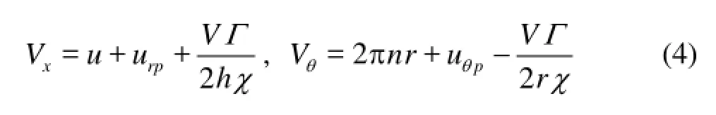
In this formulation, the propeller system is represented by a continuum disk where the section drag coefficient and effective pitch of the propeller blades are described through a preliminary tuning process based on the open-water propeller performance available from experiments or highly accurate computations. from the potential theory[5], a set of bound vortex sheets localized at the propeller-planepS, along with free-vortices shedding from rearwards, model the presence of the propeller, moreover the disturbance due to the propeller is accounted for through a potential velocity field (urp,uθp), whererandθdenote the polar coordinates onSp.
For a propeller moving at an advancing ratioJ=V/nD(Vis the hub velocity along thexdirection orthogonal to the propeller plane,nthe propeller rate of revolution andDthe propeller diameter), the disturbed velocity-potentialφrecasts[5,19,20]
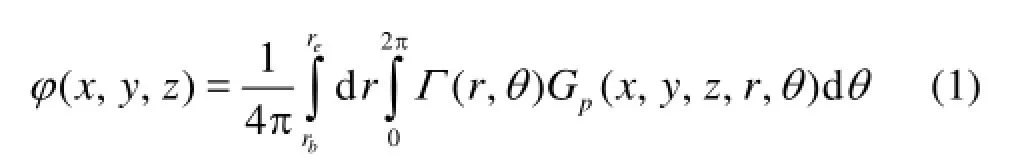
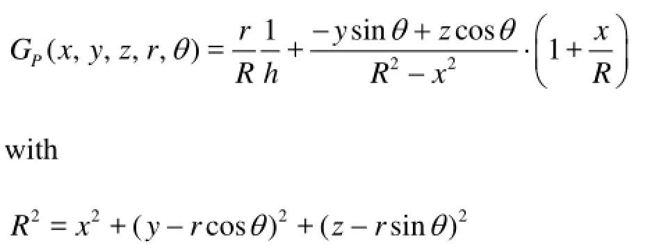
where (,,)xyzare the Cartesian coordinates of a point in the flow-field,brandgrdenote the boss andblade radius, respectively, andpGrepresents the Green function defined as[20]
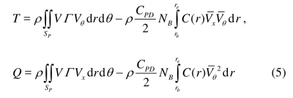
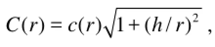
The circulation (,)rΓθrefers to the strength of the bound vortex sheet in the elemental area ddrrθof the disk, it is obtained by solving the boundary condition onpSstemming from the conservation of mass through the propeller-plane[4]
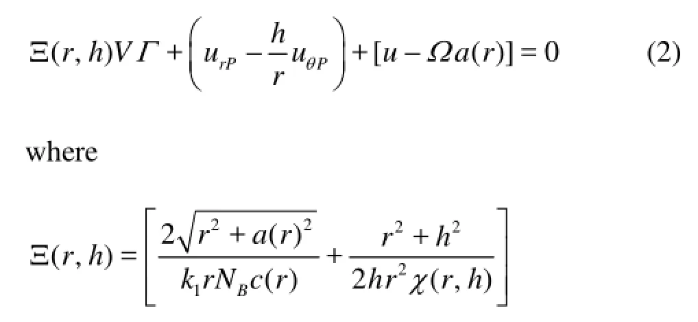
and the velocitiy componetsrpuandpuθdepend onΓ(see expression (1)). In Eq.(2), the self-induction is implicitly considered, moreover,udefines the ahead axial-velocity component of the wake field,Ω=2πn,χstands for Prandtl’s tip loss correction factor, ()aris the effective blade pitch, andBNindicates the blades number whilst 2hπ represents the pitch of the free vortices, being
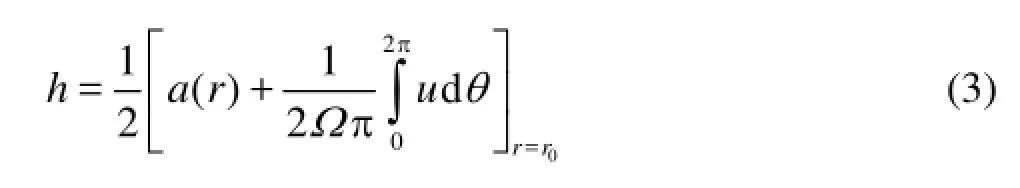
withr0=0.7re. The quantityk1is a correction factor that takes into account of the finite width of the blades and the blade-blade interaction[5]. The solution of Eq.(2) in terms of circulation distribution (,)rΓθyields the perturbed potential and, in turns, the velocity field onpS, which may be written as
1.2Theodorsen and Sears theories
Propeller loads are here obtained as radial integration of the sectional loads given by the unsteady airfoil theories. Let a coordinate axes be fixed to a thin, straight airfoil with thexaxis parallel to the flow at infinity, and with the origin at the mid-chord. For an airfoil of chord-length =2cb, moving in an incompressible flow with velocityV, subjected to a harmonic vertical translation ()htand to a pitch rate ()tαimposed about an axis atasemi-chord from the midchord (tdenotes time), the Theodorsen theory yields the unsteady aerodynamic force acting on it by combining the non-circulatory liftncL, orthogonal to the chord, with the circulatory liftcLdirected along the normal to the relative wind[21]. Specifically, the noncirculatory lift is expressed as
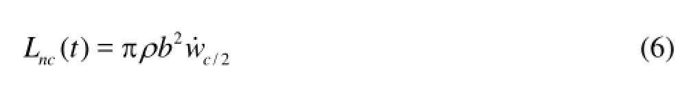
where/2cw˙ represents the time derivative of the normal component of the relative wind (upwash) evaluated at the airfoil mid-point (positive upwards).
The circulatory lift is given by
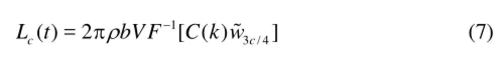
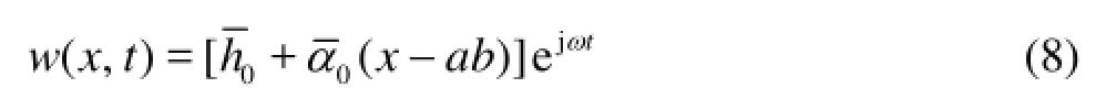
whereFdenotes the Fourier transformation,w˜3c/4=F[w3c/4] withw3c/4representing the upwash at the airfoil 3/4-chord point whereas ()Ckindicates the lift deficiency function defined in Ref.[22] in terms of the reduced frequency =/kbVω(whereωis the frequency of the harmonic motions). The application of the Theodorsen theory to marine propellers operating in a non-uniform axial-inflow may be done by assuming that the periodic upwash on the airfoil moving within the wake-field is the combination of multi-harmonics plunge and pitch motionsh(t)=hejωtandα(t)=αejωtwith constant phases (handαrepresentcomplex amplitudes). Thus, the upwashwis described as the superposition of chordwise linear distribution of velocity amplitudes with constant phases such that
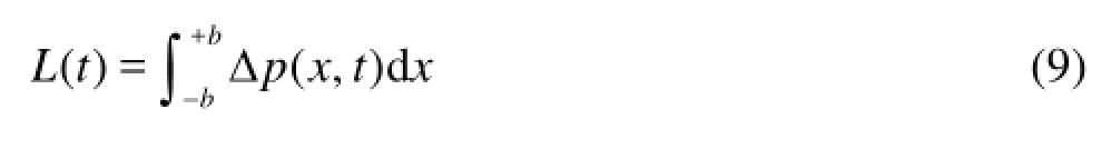
The total liftL=Lc+Lncis directly obtained by the integration of the pressure-jump long the airfoil
where, for each harmonic componentωof the onset flow, Δp˜=F[Δp] is given by[12]
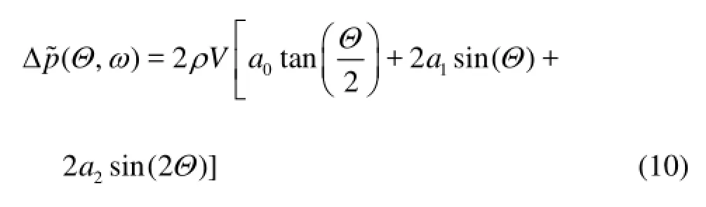
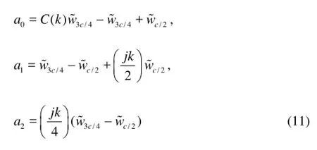
In the above equation, the variableΘ∈[0,π] is such thatx=bcosΘwhereas coefficientsa0,a1,a2are expressed as
An alternative approach to predict the unsteady loads on an airfoil passing through a spatially non-uniform flow is that proposed by Sears[12], where the upwash distribution, at any point of the airfoil and for a given frequency of the multi-harmonic onset flow, may be expressed as
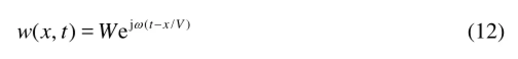
Stating that the sinusoidal gust pattern, with a constant amplitudeW, moves past the airfoil with the speedV. Assume that the wave-length of the gust isl, then 2/Vlπ denotes the frequencyωwith which the wave passes the airfoil. Following[12], the unsteady lift may be written as
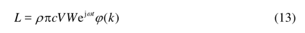
where ()kφdenotes the Sears function representing the frequency response of the lift to the gust. The lifting forceLmay be expressed as in Eq.(9) where, for each frequencyωof the wake-field, the pressurejump along the chord is[12]

In whichJn(k) is the Bessel functions of the first kind. As is shown in Eq.(12), the Sears theory represents the upwash velocity-field on the airfoil as a combination of chordwise constant distribution of velocity amplitudes with linear phases. Thus, being different from the Theodorsen model, it is able to model (linearly) the inflow phase shift between points on the airfoil-chord when a non-uniform flow is encountered. Note that, in terms of pressure-jump, the blade response to the uniform mean axial-velocity is obtained directly from Eq.(10) or Eq.(14) by imposing =0k: as expected, for the steady-state condition, both the Theodorsen and Sears formulations reduce to the Glauert theory. In the following, the Theodorsen and Sears models are applied by dividing the mean-surface of the propeller blade into a discrete number of sections and applying Eqs.(10) or (14) to each section, for each harmonic component of the inflow velocity. Further, in the time domain, the perturbed thrust recasts
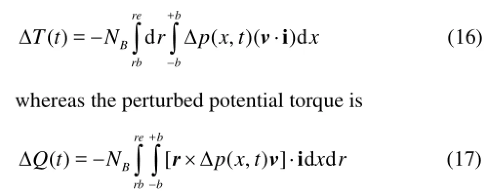
wherevis the outward unit normal to the mean surface, i denotes the unit vector aligned to the direction orthogonal to the disk-plane andris the local vector identifying the chordwise position of a point with respect to the propeller hub.
2. Numerical results
In this section the hydrodynamic performances of a marine propeller operating in a multi-harmonics wake-field characterized by a high-frequency content, are investigated. In details, the hydrodynamic loads obtained by Nakatake, Theodorsen and Sears approaches are compared with those given by a fully 3-DBEM hydrodynamic solver. To this aim, the marine propeller PROP 3714 (see Fig.1) developed at the David Taylor Ship Research and Development Center is considered.
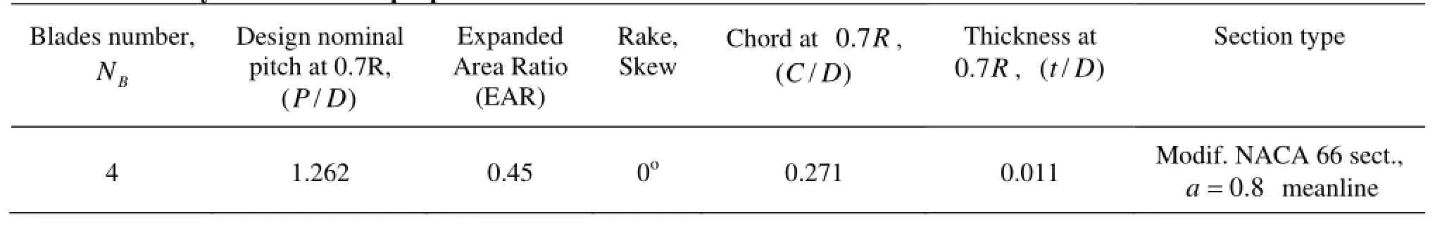
Table 1 Summary of DTRC 3714 propeller data
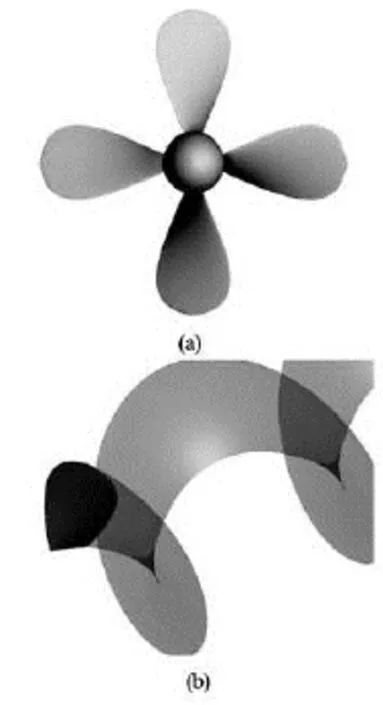
Fig.1 PROP 3714. Front view and prospectical sketch of the reference blade with potential wake
The diameter of the propeller is =D0.254 m. the operating conditions are defined by a rotational speedn=50rps and free-stream speeds ofV=12.7 m/s (J=1) andV=7.62 m/s (J=6), respectively. Table 1 summarizes some geometric features, a detailed description of the DTRC 3714 model propeller is presented in Subramanian[23].
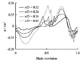
Fig.2 Axial onset flow velocity
Figure 2 depicts the azimuthal variation of the onset flowuat different radial positions on the propeller disk, as is shown, both velocity peaks and harmonic content increase toward the external boundary of the disk.
A Fourier analysis (not shown here) shows that the spectrum of this wake-field contains up to 90 harmonics, although a typical wake-field encountered by a propeller at each radial location has different features from that herein used, being reasonably defined through the first eight/ten harmonics for straight ahead motion[9], the high frequency content of the study-case inflow shown in Fig.2 allows to stress the behavior of the proposed hydrodynamic models respect to severe flow non-uniformities that may be experienced during off-design conditions (tight maneuver or crash stop, for instance).
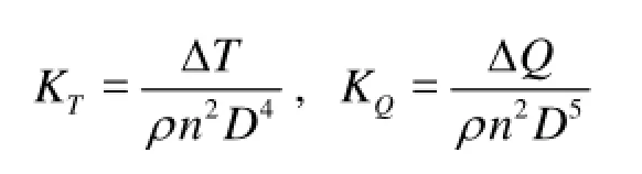
Hence, in the following, emphasis is put on the perturbed hydroloads induced by the incoming flow. The capabilities of the three methodologies in capturing the unsteady blade loads are first investigated by analyzing the response of a single-blade, working atJ=1.0, to an incoming flow derived from that of Fig.2 using the first 4, 8, 12 and 16 harmonics, respectively. In order to grasp the effect of blade loading on the propeller response, the same analysis is carried out also at =J0.6 for the inflow-type with 4 and 16 harmonics. The following definitions in terms of non-dimensional coefficients are used
whereρdenotes the water density. For the 4-harmonics inflow-type, Fig.3-top shows that the thrust signal predicted by Theodorsen almost perfectly match that obtained using the Sears theory.
With respect to BEM-converged results, the trend of the wave-form is well captured, especially in terms of signal-phase; relevant discrepancies, in the signalpeaks, are highlighted at the first quarter and at thirdquarter of the blade revolution. On the contrary, the agreement with BEM computations is good about at half and at the end of the blade revolution, corresponding to those azimuthal positions where the blade encounters large variations in the incoming flow (see Fig.2).
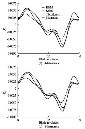
Fig.3 Blade response to the first 4 harmonics (top) and 8 harmonics (bottom) inflow
In these regions, numerical results coming from the Nakatake model exhibit signal oscillations not shown neither in BEM results nor in Theodorsen/ Sears outcomes, however, at the first quarter and at third-quarter of the blade revolution, approximately, the agreement with BEM computations is slightly better than that obtained through the airfoil theories, albeit a worsening in terms of phase signal is highlighted.
This behavior is also confirmed by the analysis of Fig.3-bottom, showing the blade response to the first 8-harmonics inflow.
By increasing the harmonic content of the incoming flow, the Nakatake approach captures, better than the Sears model, the load-peaks at the first quarter and at third-quarter of the blade revolution, thus yielding a better agreement with BEM computations (see Fig.4), however, out of this range, over-oscillations arises. In terms of signal phase, the quality of the results remains similar to that given in Fig.3. The increased harmonics content of the wake-field determines relevant discrepancies between Theodorsen and Sears predictions. This is well shown in Fig.4 depicting the blade response to 12 and 16 harmonics inflow-type. Such discrepancies consist in oscillations of the signal predicted by the Theodorsen model with respect to that given by the Sears formulation, the greater is the harmonics content of the inflow, the greater are the signal oscillations. Amplitude oscillations are larger at half and at the end of the blade revolution, that is, in those regions where higher circumferential gradients of the inflow velocity are present. This behavior is due to the fact that the Theodorsen theory describes the upwash velocity on an airfoil encountering a gust by combining basic harmonic motions having chordwise linear distribution of velocity amplitudes, with constant phases (see the Eq.(8)), in this way, each point of the airfoil is forced to experience the same signal simultaneously.
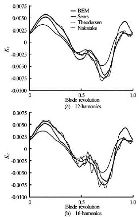
Fig.4 Blade response to the first 12-harmonics (top) and 16-harmonics (bottom) inflow
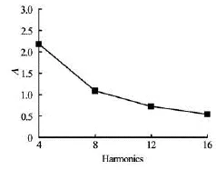
Fig.5 Minimum wavelength-chord ratio atr/re=0.75, for different harmonic contents of the onset flow
Conversely, the Sears theory accounts for a chordwise linear variation of the upwash phase (see the Eq.(12)), so that it mimics an airfoil progressively encountering a spatially, non-uniform flow. The twotheories yield comparable results as long as the sectional chord-length is smaller than, or comparable with, the minimum wavelength associated with the incoming inflow harmonic components. For a blade section located atr/re=0.75, Fig.5 shows the ratioΛbetween the minimum wavelength associated with the onset-flow and the local chord-length, for the 4, 8, 12, 16-harmonics inflow, respectively. As is expected,Λis greater than one for the 4 and 8-harmonics inflows, whilst it becomes less than one for an inflow-type with higher frequency content. This result states that the Theodorsen theory may be used to study the unsteady response of an airfoil travelling into a non-uniform flow until the wavelength associated with the (relevant) higher frequencies upwash components is greater, or at least, comparable to local chord-length (low reduced frequency).
Fig.6 Comparison of the inflow velocity between 2-D theories and prescribed input (quarter chord atr/re=–0.75)
As a further support of this consideration, Fig.6 depicts the upwash velocity at the quarter chord point (from the leading edge) for the blade section located atr/re=0.75. In particular, the normal component of the velocity field for the inflow-type with 4 and 16 harmonics, is reconstructed by the Theodorsen and Sears theories, and compared with the prescribed input. As expected, both theories behave similarly and well match the prescribed input in case of the 4-harmonics inflow, differently, at the highest harmonic content, Theodorsen introduces spurious oscillations in the reconstruction, whereas Sears resolves correctly the inflow wave form.
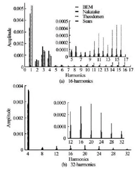
Fig.7 Blade response spectrum at the first 16-harmonics (top), 32-harmonics (bottom) inflow
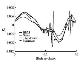
Fig.8 Blade response to 90-harmonics inflow
An in-depth analysis of the correlations among hydrodynamic predictions is given in Fig.7 that depicts the spectrum of the thrust signal for the 16-harmonics inflow-type. As is shown, for the 1st and 2nd harmonics, the Nakatake model yields amplitudes that are closer to BEM results than Theodorsen/Sears outcomes. For higher harmonics, the Sears formulation yields predictions closer to BEM results almost throughout the whole spectrum. This fact confirms the difficulty of the Nakatake theory in capturing local high-frequency change of the onset flow. The load spectrum also points out that the Theodorsen theory is reliable up to the 3/revfrequency since for higher values the amplitudes of the response tend to diverge. All the aspects discussed above, may be well observed inFig.8, where results from the Theodorsen, Sears and Nakatake approaches are compared with BEM outcomes for the inflow velocity characterized by 90-harmonics.
As is shown, results from the Theodorsen formulation appear to be completely unreliable, the Sears computations well capture the unsteady thrust at azimuthal regions where the blade encounters large variations in the incoming flow, albeit some lower level of agreement is observed out of these regions; results from the Nakatake model, indeed, exhibits a better level of accuracy in those regions where the inflow velocity is governed by low-frequency terms.
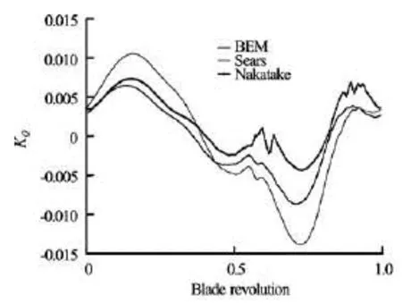
Fig.9 Blade response in terms of torque
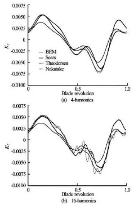
Fig.10 Blade response to 4 (top) and 16 (bottom) harmonics inflow for =J0.6
Similar considerations may be done for the torque signal, for instance, Fig.9 compares the perturbed torque predicted by the Sears and Nakatake theories with BEM-converged results, in case of 90-harmonics. The effect of the blade loading is investigated by analyzing the blade response to an incoming flow with 4 and 16 harmonics, respectively, at =J0.6. At lower values of the advancing ratioJ, propeller blades experience higher steady hydroloads so that perturbed loads are expected to be less important. This is confirmed in Fig.10, where results are qualitatively similar to those obtained at =J1.0, are characterized by signal peaks slightly less. On the base of these considerations, the further analysis is focused on the perturbative thrust delivered at =J1.0.
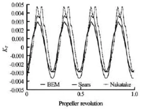
Fig.11 Four-bladed propeller response in terms of thrust
The analysis of a multi-bladed propeller, shown in Fig.11 for =J1.0 and 90-harmonics inflow-type, confirms that the Nakatake model over-predicts the thrust signal in those azimuthal regions dominated by high-frequency hydrodynamic effects, giving rise to a wave-form not predicted by the BEM-based hydrodynamics, differently, the Sears model describes quite well these effects. About low-frequency hydrodynamic effects, governing the minimum values of the thrust, the Nakatake model provides results closer to BEM computations than the Sears one.
In order to understand the reason of such a behavior, an analysis on the role played by the potential wake is addressed in the following. To this aim, it is useful to think the wake in terms of vorticity vectors aligned (mainly) normal and parallel to the trailing edge of the blade[11]: the former (trailed-vorticity), is related to the circulation spanwise distribution and mostly accounts for 3-D effects, whereas the latter component (shed-vorticity) is associated to the time rate of change of lift on the blade.
As wass discussed in Subsection 1.2, the Sears theory needs the knowledge of the boundary condition in terms of normal component of the velocity (upwash) at specific points along the sectional chord. The more accurate is the evaluation of the blade upwash and the more accurate are the predictions: however, computations previously performed, do not take into account for the upwash induced by the whole blade-wake vor-ticity, since only the close shed-vorticity, generated by the examined sections, is modeled by the lift deficiency function[11,21].
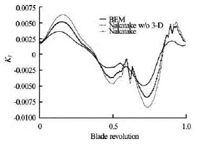
Fig.12 Behavior of Nakatake thrust prediction with and without 3-D effects
Propeller blades may be significantly perturbed by the complex velocity field self-induced by the propeller wake, especially for low advance-ratio, where the wake is closer to the propeller disk; some of these wake-effects are somehow described in the Nakatake theory through a set of helicoidally trailed-vortices downstream the propeller plane whereas those related to the shed-vorticity are completely neglected[4,11]. Trailed-vorticity is related, for instance, to 3-D flow effects, for a single-bladed propeller, Fig.12 highlights the beneficial effects on hydrodynamic predictions of the inclusion of these trailed-vortices.
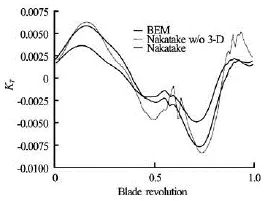
Fig.13 Comparison among BEM, Sears and Nakatake (w/o 3-D effects) thrust predictions
As is shown, for the high-frequency incoming flow (90-harmonics), the presence of trailed-vortices considerably improves the agreement between BEM results and Nakatake outcomes. Moreover, Fig.13 shows how outcomes from the Nakatake model without trailed-vorticity effects are closer to those predicted by the Sears theory in terms of signal-peaks, even if relevant discrepancies remain in those regions where the incoming flow is much irregular. These discrepancies are mainly due to the lack of the shed-vorticity effects into the Nakatake model: this is shown in Ref.[24] where for a rotating blade subjected by an incoming periodic gust of low and high frequency, as the frequency increases, farther wake portions reduce their influence (because of the algebraic null contribution from short vorticity wave lengths), as well as the corresponding 3-D effects. Hence for an upwash oscillating at very high frequency, only a limited wake region behind the trailing edge still affects the sectional loads, but this contribution is exactly included in the sectional aerodynamics theories.
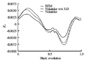
Fig.14 Comparison among BEM and Sears (with and without wake effects) thrust predictions
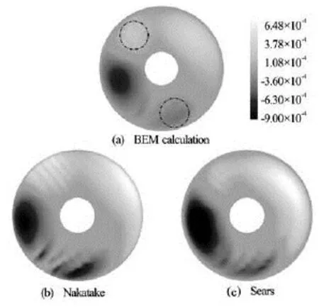
Fig.15 Comparisons among BEM calculations (top), Nakatake (bottom left) and Sears (bottom right) results. Inside the dotted-dashed circles the response to the higher harmonic content of the inflow is highlighted
These considerations are a guideline towards an enhanced propeller modeling suited for treating both high-frequency onset flow and (some) 3-D effects. For the sake of completeness, hereafter, this study is preliminarily addressed through the use of the Sears theory, including into the upwash distribution perturbing each blade section, those effects from trailed-vortices and that part of shed vortices not already considered in the theoretical model. To this aim, following the approach presented in Ref.[18], the hydrodynamic BEM solver is applied to determine (only) the upwash induced bywake vorticity: the result of this analytical/numerical approach, shown in Fig.14 for the 90-harmonics inflow-type, highlights an enhancement of the perturbed thrust with respect to fully-BEM computations. In this procedure, computational costs remain limited, in that using the BEM tool, the evaluation of the numerically converged blade downwash distribution is significantly faster than the evaluation of the numerically converged blade pressure distribution. Although preliminary, such a result encourages further investigations on the combined use of a BEM solver with a sectional aerodynamics formulation to assess a reliable/fast solver for the hydrodynamic analysis of propellers in a multicyclic wake-field. A general view of the quality of the predictions given by the proposed methods may be assessed in Fig.15. It concerns the contour levels of the perturbed thrust obtained by the Nakatake model, the Sears theory (without blade-wake vorticity induced effects) and BEM-converged hydrodynamics, for the 90-harmonics inflow. This figure confirms the capability of the Sears theory of capturing better than Nakatake the hydroloads generated by high-frequency inflow, in terms of both peak values and phase (see the areas located at the azimuthal positions inside the dotted and dashed circles). Differently, out of these regions the Nakatake formulation yields results closer to BEM computations. Before concluding, the one-bladed propeller response computed by the Hough and Ordway model, properly modified to deal with nonhomogeneous onset flows, is presented in Fig.16.
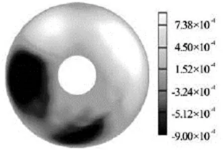
Fig.16 Hough and Ordway response in terms of thrust distribution
As is shown, thrust peaks are over-predicted respect to the Nakatake-based results (roughly doubled) and also the azimuthal load distribution is not well described. This result let the authors emphasize how the use of inherently steady approaches may yield less accurate predictions in case of high-frequency inflow impinging the propeller disk.
3. Conclusions
Three hydrodynamic models based on the simplified theories of Nakatake, Theodorsen and Sears, respectively, have been investigated. They are applied to predict thrust and torque delivered by a marine propeller working within an axial non-homogeneous inflow dominated by spatial high-frequency local changes. Such spatial non-uniformity induces periodic time-varying hydroloads, whose evaluation may be of interest for the analysis of vibratory hub-loads and ship dynamics. Numerical results show a comparison among these approaches, within the framework of potential flows, hydrodynamic predictions coming from a fully-3-D unsteady BEM solver are used as reference results. Investigations show that the Theodorsen hydrodynamics may be used as long as the wavelength associated to the higher harmonics of the onset flow is greater than the maximum chord-length of the spanwise sections, differently, results are completely unreal. On the contrary, the Sears predictions match quite well with the BEM-computations in terms of signals trend, especially in those azimuthal regions where the inflow is much irregular, highlighting the capability of this model to describe high-frequency hydrodynamic loads. However signal peaks, mainly related to the low-frequency blade response, are overpredicted with respect to BEM results. A devoted analysis highlights that these overestimations are due to blade-wake effects associated to the trailed vorticity not taken into account in the 2-D theory.
The Nakatake computations denote the capability of capturing, better than Sears, the low-frequency hydrodynamic response of the propeller. As was discussed, this is due to the presence of a set of trailed vortices rearwards the propeller disk, directly modeled into the formulation. However, a noticeable worsening of the results arises at higher frequency because the unsteady hydrodynamic effects induced by the shed vorticity are not considered. In terms of computational cost, both models are comparable since they take few seconds to perform a calculation.
From the analysis of the perturbed thrust distribution upon the propeller disk, it is possible to get an overview of the potentialities of Nakatake and Sears methods respect to the Hough and Ordway model, herein modified to describe (in a quasi-steady fashion) the effects of inflow non-uniformities. Comparisons show that the perturbed loads evaluated by Hough and Ordway are inaccurate in case of high-frequency inflow impinging the propeller disk. Investigations carried out throughout the paper make the Nakatake and Sears theories appealing (fast) hydrodynamic models for the analysis of propellers in multi-cyclic inflow or for CFD applications aimed at the study of hull-propeller configurations in off-design conditions.
[1] LARSSON L., STERN F. and VISONNEAU M. CFD Workshop in Ship Hydrodynamics-Results of the Gothenburg 2010 Workshop[C].Proceedings of Gothenburg 2010 Workshop.Gothenburg, Sweden, 2010.
[2] PHILLIPS A. B., TURNOCK S. R. and FURLONG M. E. Accurate capture of rudder-propeller interaction using a coupled blade element momentum-RANS approach[J].Ship Technology Research,2010, 57(2): 128-139.
[3] SIMONSEN C., STERN F. RANS maneuvering simulation of Esso Osaka with rudder and a body-force propeller[J].Journal of Ship Research,2005, 49(2): 98-120.
[4] NAKATAKE K. A practical method to calculate propulsive performance of ships[R]. Fukuoka, Japan: Kyushu University, 1981, 41.
[5] YAMAZAKI R. A study on screw propellers[R]. Fukuoka, Japan: Kyushu University, 1960, 19.
[6] BROGLIA R., DURANTE D. and DUBBIOSO G. et al. Turning ability characteristics study of a twin screw vessel by CFD[C].Marine ECCOMAS.Lisbon, Portugal, 2011, 266-267.
[7] BADOE C., PHILLIPS A. and TURNOCK S. R. Influence of drift angle on rudder-propeller interaction[C].Proceedings of 15th Numerical Towing Tank Symposium.Cortona, Italy, 2012, 1-6.
[8] PHILLIPS W. F., ANDERSON E. A. and KELLY Q. J. Predicting the contribution of running propellers to aircraft stability derivatives[J].Journal of Aircraft,2003, 40(6):1107-1114.
[9] CARLTON J. S.Marine propellers and propulsion[M]. Oxford, UK: Butterworth Heinemann, 2012.
[10] TAHARA Y., WILSON R. and CARRICA P. Comparison of free-surface capturing and tracking approaches in application to modern container ship and prognosis for extensions to self-propulsion simulator[C].Proceedings of CFD Workshop Tokyo.Tokyo, Japan, 2005.
[11] LEISHMANN J. G.Principles of helicopter aerodynamics[M]. Cambridge, UK: Cambridge University Press, 2006.
[12] FUNG Y. C.An introduction to the theory of aeroelasticity[M]. New York, USA: Dover Publications, 2008.
[13] GENNARETTI M., MOLICA COLELLA M. and BERNARDINI G. Analysis of helicopter vibratory hub loads alleviation by cyclic trailing-edge blade flap actuation[J].The Aeronautical Journal,2009 113(1146): 549-556.
[14] LIM J. W., YU Y. H. and JOHNSON W. Calculation of rotor blade-vortex interaction airloads using a multipletrailer free-wake model[J].Journal of Aircraft,2003, 40: 1123-1130.
[15] GENNARETTI M., TESTA C. and BERNARDINI G. Frequency-domain method for discrete frequency noise prediction of rotors in arbitrary steady motion[J].Journal of Sound and Vibration,2012, 331(25): 5502-5517.
[16] LEONE S., TESTA C. and GRECO L. et al. Computational analysis of self-pitching propellers performance in open water[J].Ocean Engineering,2013, 64: 122-134.
[17] SALVATORE F., TESTA C. and GRECO L. A Viscous / inviscid coupled formulation for unsteady sheet cavitation modelling of marine propellers[C].5th International Symposium on Cavitation CAV2003.Osaka, Japan, 2003.
[18] GRECO L., SALVATORE F. and DI FELICE F. Validation of a quasi-potential flow model for the analysis of marine propellers wake[C].Proceedings of 25th ONR Symposium on Naval Hydrodynamics.St. John’s, Newfoundland, Canada, 2004.
[19] YAMAZAKI R. On the propulsion theory of ships on still water-Introduction[R]. Fukuoka, Japan: Kyushu University, 1968, 27.
[20] YAMAZAKI R. On the propulsion theory of ships on still water–A case of thin ship[J]. Fukuoka, Japan: Kyushu University, 1972, 31.
[21] BISPLINGHOFF R. L., ASHLEY H.Principles of aeroelasticity[M]. New York, USA: Dover Publications, 2002.
[22] PHILLIPS W. F.Mechanics of flight[M]. New York, USA: John Wiley and Sons, 2004.
[23] SUBRAMANIAN S., MUELLER T. J. An experimental study of propeller noise due to cyclic flow distortion[J].Journal of Sound and Vibration,1995, 183(5): 907-923.
[24] GENNARETTI M., TESTA C. and BERNARDINI G. An analytical-numerical aerodynamic formulation for efficient aeroacoustic analysis of rotorcraft[C].INTERNOISE12.New York, USA, 2012.
[25] BROGLIA R., DUBBIOSO G. and DURANTE D. et al. Simulation of turning circle by CFD: Analysis of different propeller models and their effect on maneuvering prediction[J].Applied Ocean Research,2013, 39: 1-10.
[26] MOLLAND A., TURNOCK S. and HUDSON D.Ship resistance and propulsion[M]. Cambridge, UK: Cambridge University Press, 2011.
Appendix A: The modified hough and ordway actuator disk model
The Hough and Ordway actuator disk model[7]is broadly used in CFD simulations for marine hydrodynamics. The original model aims to solve the hydrodynamic flow field surrounding a propeller working in open water fashion, i.e., axial symmetric and uniform inflow. On the basis of the momentum theory and the assumption of optimal radial circulation distribution[22], propeller effects can be represented via axial and tangential body forces, defined in the following equationns:
whereris a general radial position,TKandQKare the thrust and torque coefficients andJis the advance coefficient,PRandHRare the non-dimensional propeller and hub radius andPDXis the mean chord length projected onto the propeller axial plane.
In order to mimic the propeller load variation due to dynamic motion of the vessel (maneuver or navigation in a seaway), the magnitude of the propeller loading[6,25]is not prescribed in advance, but through the use of the propeller open water curves. In particular, at each time step, the average longitudinal velocityavuin correspondence of the propeller plane is evaluated to predict an instantaneous advance coefficient ()Jt
whereDandnrepresent respectively the propeller diameter and the rate of revolution. Once ()Jtis evaluated, the propeller loading can be identified from the open water curves in terms ofTKandQK, which represent the proportionality factor of the axial and tangential body forces described in Eq.(A2).
In order to represent physically the propeller response to a spatially variable inflow, the previous approach has been reduced to each element of the disk.
In particular, a local advance coefficient is evaluated at every position

wherexuis the axial component of the inflow at the generic polar position on the disk. This procedure can be considered as a generalization of the equivalent advance coefficient idea firstly introduced by Gutshe for the analysis of propellers working in pure oblique flow[26]. In a similar manner as above, the local loadingKT(r,θ,t) andKQ(r,θ,t) (and the body forces magnitude, see Eq.(A2)) is easily estimated from the propeller open water curves. It is worthy to note that the equivalentJassumption provides, to the actuator disk model, a physical sensitivity to any non-homogeneous wake distribution impinging the propeller disk. In the framework of CFD simulations of ship motions, which are extremely demanding from the computational point of view, it can be still considered attractive due to its simple formulation.
10.1016/S1001-6058(13)60445-X
* Biography: DURANTE D. (1979-), Male, Ph. D., Researcher

- 水动力学研究与进展 B辑的其它文章
- Analysis of shear rate effects on drag reduction in turbulent channel flow with superhydrophobic wall*
- Numerical study of flow fluctuation attenuation performance of a surge tank*
- A three-dimensional hydroelasticity theory for ship structures in acoustic field of shallow sea*
- Experimental study by PIV of swirling flow induced by trapezoid-winglets*
- The calculation of mechanical energy loss for incompressible steady pipe flow of homogeneous fluid*
- A preliminary study of the turbulence features of the tidal bore in the Qiantang River, China*