
Hydrodynamic performance of flexible risers subject to vortex-induced vibrations*
2013-06-01 12:29:57ZHANGHuiYANGJianminXIAOLongfeiLUHaining
水动力学研究与进展 B辑 2013年1期
ZHANG Hui, YANG Jian-min, XIAO Long-fei, LU Hai-ning
State Key Laboratory of Ocean Engineering, Shanghai Jiaotong University, Shanghai 200240, China, E-mail: zh.hui@sjtu.edu.cn
Hydrodynamic performance of flexible risers subject to vortex-induced vibrations*
ZHANG Hui, YANG Jian-min, XIAO Long-fei, LU Hai-ning
State Key Laboratory of Ocean Engineering, Shanghai Jiaotong University, Shanghai 200240, China, E-mail: zh.hui@sjtu.edu.cn
(Received March 5, 2012, Revised December 16, 2012)
The Vortex-Induced Vibration (VIV) displacements are determined from both the measured accelerations and strains in a series of VIV experiments. Based on the results, the forces in the longitudinal, transversal and tangential directions are estimated by using the finite element method with and without considering the interactions between adjacent elements. The numerical simulation indicates that the method considering the interactions performs better in the estimation of the forces. The component of the transversal force in phase with the acceleration is associated with the added mass coefficient. The estimated added mass coefficients take abnormally high values at the locations where the displacements are small. An improved formula based on the L'Hospital's rule is pro- posed to deal with this problem. The results show the advantage of this formula in estimating the added mass coefficients at the loca- tions with small VIV displacements.
Vortex-Induced Vibration (VIV), flexible risers, hydrodynamic force, added mass coefficient
Introduction
The bluff cylindrical marine structures under the periodic shedding of vortices in ocean currents can be excited into resonant vibrations. This phenomenon is called the Vortex-Induced Vibration (VIV). The VIV may cause unacceptable levels of fatigue damages of flexible structures[1-3].
In the current engineering practice, the riser VIV design is typically based on empirically derived models[4,5]. The empirical hydrodynamic coefficients adopted in these models are estimated from the experimental data of rigid cylinders subject to forced oscillation experiments[1,6]. Due to the complex VIV behaviours of the long flexible risers, the hydrodynamic coefficients do not usually agree with the empirical hydrodynamic coefficients adopted in empirical models. The estimation of the hydrodynamic coefficients is necessary in the VIV analysis of the long flexible risers.
A large number of VIV experiments on long flexible risers were conducted in the past decade. Based on the measurements of accelerations and strains, the VIV response is reconstructed with the modal analysis. Then the forces in the longitudinal, transversal and tangential directions are estimated by using the finite element method[7-9]. The estimated transversal force hereinafter referred to as the hydrodynamic force could be split into two components, one in phase with the velocity and the other in phase with the acceleration. Based on the assumption that the VIV response and the force are both harmonic[10,11], the component of the hydrodynamic force in phase with the acceleration is associated with the added mass coefficient. The added mass coefficient at one location is proportional to the ratio of the transversal force and the displacement at the same location.
Previous studies[9,12,13]show that the added mass coefficients take abnormally high values when the VIV displacement is small. This phenomenon is inconsistent with the engineering practice. Until now, the formula used to estimate the added mass coefficients has not been paid enough attention. It can be observed that the hydrodynamic forces are also small at these locations with small VIV displacements. Hence, the small errors introduced in the estimation of the hydrodynamic force and the VIV displacement willcause the abnormal high value of the added mass coefficient.
To obtain the hydrodynamic forces and the added mass coefficients of a flexible riser more accurately, the VIV experimental data of a flexible riser under a uniform current is selected to verify the methods in this study. To illustrate the difference caused by the hydrodynamic forces in the estimation of the added mass coefficients, the hydrodynamic forces are predicted by two finite element methods with and without considering the interactions between adjacent elements. An improved formula based on the L'Hospital's rule is proposed to estimate the added mass coefficient of a flexible riser. The results quantitatively show that the estimation of the hydrodynamic forces by using the finite element method considering the impacts from the adjacent elements is more accurate. And the improved formula gives good estimations of the added mass coefficients in the places of small VIV displacements.
1. Numerical theory
Directly measuring the hydrodynamic forces along flexible risers is usually a challenging task in experiments. As a consequence, these forces are calculated based on the measured time series of responses along the risers.
The estimation of the hydrodynamic forces and the coefficients is carried out in the following steps:
Step 1
Estimate the modal weights with the modal analysis method.
Step 2
Determine the range of modes and reproduce the displacement.
Step 3
Estimate the bending moments and the shear forces.
Step 4
Obtain the hydrodynamic forces along the flexible riser.
Step 5
Estimate the hydrodynamic coefficients based on the empirical equation and the improved added mass coefficient formula.
The methods of obtaining the displacement, the bending moments, the shear forces, the hydrodynamic forces and the coefficients are described in the following subsections.
1.1 Modal analysis
The analysis of the measured VIV response is done through a modal approach based on the assumption of sinusoidal modal shapes. The details can be found in Ref.[14,15].
The estimated VIV displacement response is reconstructed by the contribution modes according to

The error in the reconstructed response highly depends on the selection of the contribution modes in the modal analysis. The number of sensors limits the highest mode included in the analysis according to the Nyquist law. And the low modes are very sensitive to the measurement noise. Lie and Kaasen[14]found that it is hard to accurately detect the mode weight of a low mode in the analysis. Thus, in this analysis, very low modes are not included.
1.2 Bending moments and end shear forces
Given the reconstructed displacement xˆ( t, z), the bending moment and the shear force on any element of the flexible riser can be calculated based on the following equations:
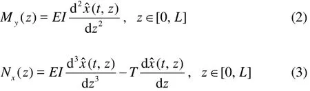
where My(z )is the bending moment along the riser in theyaxis,Nx(z )is the shear force along the riser in thexaxis,EI is the bending stiffness, and T is the axial tension, which is assumed as a constant.

Fig.1 The flexible riser subject to unknown forces
1.3 Hydrodynamic forces
To determine the hydrodynamic forces, a flexible riser with the pinned-pinned boundary condition is considered. The current profile along the flexible riser is given.
Figure 1 shows the schematic diagram of the flexible riser subject to the hydrodynamic force f( z ). The hydrodynamic forces are estimated by the methods with and without considering the interactions between adjacent elements, respectively.
Method 1
As shown in Fig.2, the hydrodynamic forces on each element are estimated without considering the impacts from adjacent elements. The hydrodynamic force f( zn)is calculated as

where f( zn)is the hydrodynamic force on the nth element,znthe distance of the nthelement from the origin O,M( zn)and M( zn-1)are the right and left bending moments of the nt helement, respectively,x( zn-1)and x( zn)the displacements of Points A and B on the nt helement,N( zn-1)is the left shear force on the nt helement, and Ln=znzn-1the length of the nt helement.

Fig.2 Method 1: Without the interactions
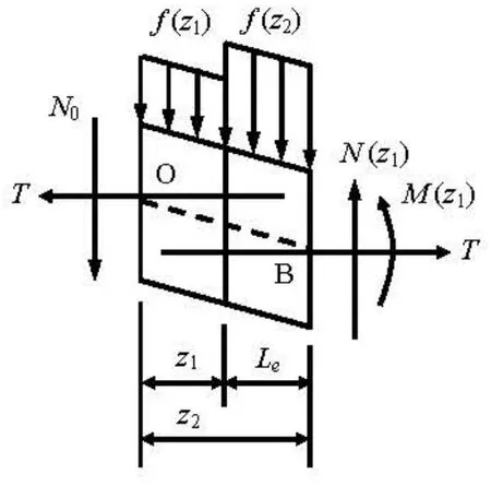
Fig.3 Method 2: With the interactions
Method 2
As shown in Fig.3, the hydrodynamic forces on each element are estimated considering the impacts from adjacent elements. With this method, the hydrodynamic force on each element should be calculated consecutively until reaching the last element.
Note that the length of all elements is the same and defined as Le. The hydrodynamic force on the first element is determined based on Eq.(5). The hydrodynamic forces on the second element are determined based on Eq.(6), with consideration of the relationship between two elements. The hydrodynamic forces on the nthelement are calculated by Eq.(7).
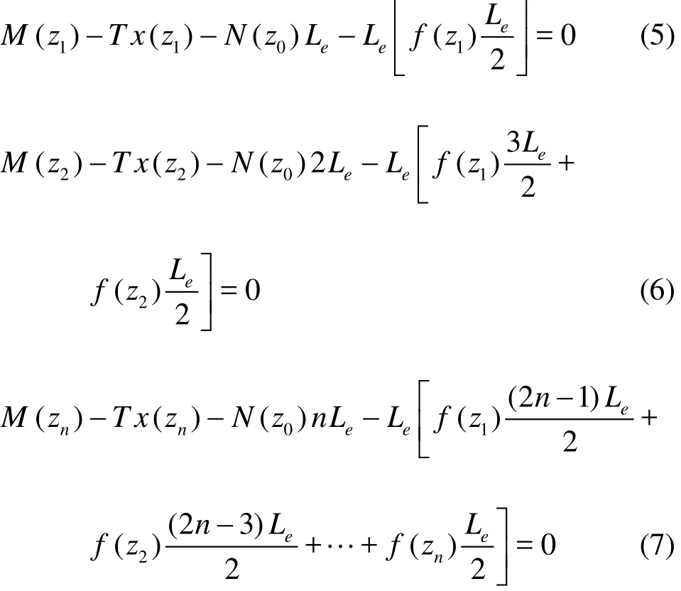
Equations (5), (6) and (7) can be rewritten in the matrix form

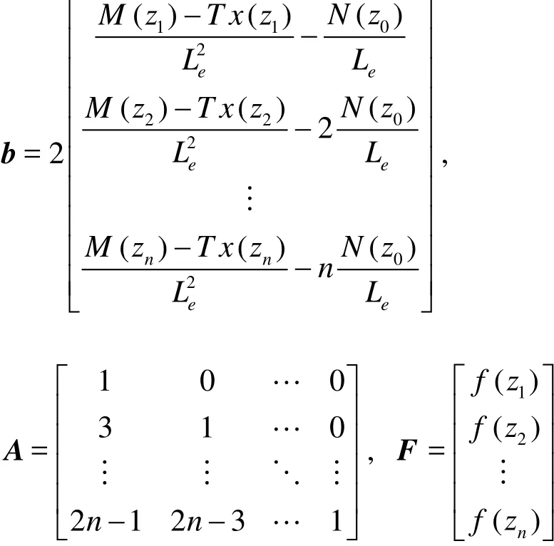
Note that the positive directions of the displacements, the forces and the bending moments at the cross-section of each element are defined as shown in Figs.2 and 3.
1.4 Hydrodynamic coefficient
Assume that the VIV displacement and the force on the elements are both harmonic, then the added mass coefficient can be determined as[11]

whereρis the fluid density,D the outer diameter of the riser,x0[(zn-1+zn)/2]the amplitude at the centre of the nt helement, and ωthe dominant response frequency.
It has been found that the added mass coefficients take extremely large values when the responses are small. Maincon et al.[8]stated that small measurement errors could result in large errors for the estimated forces. Wu[9,12,13]used a similar methodology to estimate the hydrodynamic forces along the riser and observed that the added mass coefficients take large values for a small dimensionless amplitude ratio, defined as A/ D , in which A is the VIV response amplitude, and D the diameter of the test flexible riser.
To solve this problem, Eq.(10) is rewritten as Eq.(11), and the L'Hospital's rule is applied at the positions of the flexible riser where small responses are observed.

2. Experimental set-up
The latest model tests available for the verification are the ExxonMobil tests and the NDP tests conducted in 2003. Both of the pipes tested in these experiments are densely instrumented. The ExxonMobil tests provide a good spatial resolution to determine various empirical coefficients, while the response modes in the NDP tests are higher than those in the ExxonMobil tests and the response is a combination of standing and traveling waves. The ExxonMobil tests are chosen to demonstrate the methods used in this study.
The model test was undertaken by the ExxonMobil at the Marintek in June 2003. A long, flexible brass cylinder attached to a rotating test rig used in the experiment is shown in Fig.4. The rotating test rig system consists of a long vertical cylinder, denoted by “A” in the schematic diagram. There are two horizontal arms in opposite directions at the top of the cylinder, B, and there is one horizontal arm at the bottom, C. D is a sloping beam. The test riser is 9.63 m in length and 0.02 m in diameter. One end of the riser is fastened to the outer point of the bottom arm. The other end is fastened to the outer or inner point of the top arm, to simulate the uniform and the sheared current profiles. The rotating test rig system also includes a spring system and a heave compensation system.
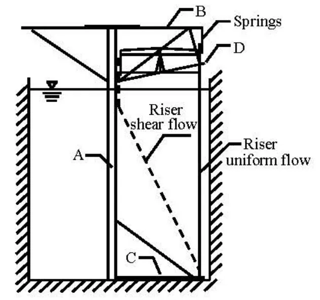
Fig.4 Schematic diagram of rotating rig and riser[16]
On the pipe, 35 strain gauges are arranged in the in-line direction, 17 strain gauges in the cross-flow direction and 8 accelerometers in both directions. The strain gauges in the cross-flow direction are distributed evenly on the riser model, with a distance of 0.265 m. The cross-flow strain gauges are located at every other in-line strain gauges, and the accelerometers are distributed at every fourth in-line strain gauges. More details of the layouts of the strain gauges and the accelerators are found in Tognarelli et al.[16]. The sampling frequency of all the instruments is 1 000 Hz. The speed of the current is in the range of 0.2 m/s to 2.38 m/s.
3. Results and discussions
Main parameters of the flexible riser model are shown in Table 1.

Table 1 Main parameters of the flexible riser model[4]
3.1 Case I: Sinusoidal distributed displacement with constant amplitude
Case I is to compare the capability of Method 1 and Method 2 in estimating the hydrodynamic forces and eliminating the abnormally high value of the added mass coefficient when the VIV response is small.
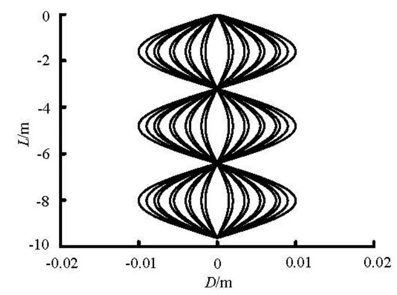
Fig.5 Response snapshots (Case I)
The single-mode VIV response of the flexible riser is assumed as

Tognarelli[16]indicated that seven modes are excited under a uniform current with the velocity of 1.12 m/s and its in-line response frequency is about 16 Hz. Based on his observation, the response frequency in Case I is assumed as

Response snapshots for Case I are shown in Fig.5, whereL is the length of the riser, andD the displacement of the riser.

Fig.6 Estimated force amplitude (Case I)
Figure 6 shows the hydrodynamic forces obtained from the two methods and from the dynamic equation. Figure 6 indicates that the estimated hydrodynamic forces obtained with both methods agree with the true hydrodynamic force obtained from the dynamic equation.F is the force on the riser.

Fig.7 Added mass coefficient (Case I)

Fig.8 Absolute errors of the added mass coefficient for Method 1 and Method 2 (Case I)
From Figs.5 and 6, it can be seen that both the response and the force are harmonic. This feature of the VIV is observed when the VIV is dominated by a single frequency and a standing wave, as often the case at the low excited mode. As a self-excited and self-suppressed motion, the VIV is strongly nonlinear.The excited force is a function of the response. Thus, the excited force is periodic but not pure harmonic in space. However, a periodic force in space always could be expanded into the sum of many harmonic terms.

Fig.9 Acceleration spectra in both cross-flow and in-line directions (1.12 m/s, Test 1111)
Five added mass coefficients for Case I are shown in Fig.7, including the added mass coefficients estimated by three types of the hydrodynamic force using Eq.(10) (True Ca, Method 1 and Method 2) and the added mass coefficients estimated by the improved Eq.(11) (Method 1*and Method 2*).
As shown in Fig.7, the added mass coefficient takes large values when A/ D ratio is small (see Method 1 and Method 2). However, this phenomenon disappears in Method 1*and Method 2*where the added mass coefficients are calculated based on the improved formula given in Eq.(11). Figs.6 and 7 show that the small difference of the forces can result in large errors in calculating the added mass coefficient when the VIV response is small. Figure 7 also indicates that Method 2/Method 2*is better than Method 1/ Method 1*in estimating the added mass coefficients, especially in cases of small amplitude ratios.A is the added mass coefficients and the amplitude ratio.
To further show the advantages of Method 2, the absolute errors of the added mass coefficient are calculated in this section. The absolute error is defined as the difference between the added mass coefficient cal-culated by Method 1/2 and that obtained by the true force Fig.8 shows the absolute errors of the added mass coefficient for Method 1 and Method 2. When the VIV response is large, the absolute errors for both methods are roughly the same. When the VIV response is close to zero, the absolute error of Method 1 is larger than that of Method 2, and the difference between them can be significant. Compared to the large variation of Method 1, the variation of the absolute error for Method 2 is much smaller. Figure 8 quantitatively indicates that Method 2 is better than Method 1 in estimating the added mass coefficients, especially for the cases of small amplitude ratios. ER is the absolute error of the riser.
3.2 Case II: uniform current of 1.12 m/s (Test 1111)
A uniform current with velocity of 1.12 m/s (Test 1111) is selected from the Datasets of ExxonMobil to estimate the VIV response and the hydrodynamic force of the flexible riser in both cross-flow and inline directions. It is found that the response is dominated by standing waves and a single frequency. The results also validate the formula for the improved added mass coefficient and its capability of solving the problem mentioned above.
Tognarelli et al.[16]indicated that four excited modes are observed on the flexible riser under a uniform current with velocity of 1.12 m/s and the response frequency is about 8 Hz. The typical power spectral densities of both cross-flow and in-line accelerators under the uniform current with velocity of 1.12 m/s are shown in Fig.9.
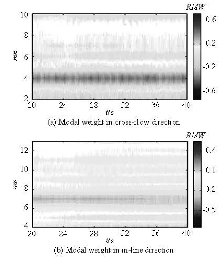
Fig.10 Contours of the modal weight in the cross-flow and inline directions under uniform current,U =1.12 m/s
Using the modal analysis, the time series of the modal weights in both cross-flow and in-line directions are obtained. Figure 10 shows the contours of the modal weight in both cross-flow and in-line directions on the flexible riser. The responses in the crossflow and in-line directions are dominated by the 4th and 7th modes, respectively.mn is the mode number, and RMW the root-mean-squares (rms) modal weight of the riser.

Fig.11 rms modal weight, bare riser, uniform current,U= 1.12 m/s

Fig.12 Contours of the cross-flow displacement response under uniform current,U =1.12 m/s
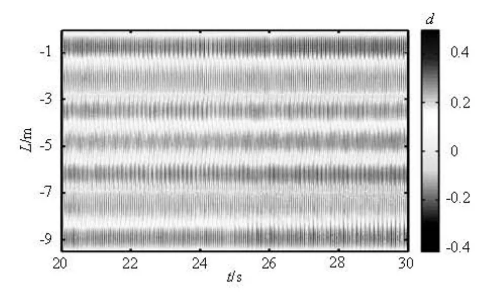
Fig.13 Contours of the in-line displacement response under uniform current,U =1.12 m/s
The contributions of different modes are shown in Fig.11. Compared to the dominant mode, the modes with similar order of contribution magnitude are sele-cted to reproduce the VIV displacement response. As seven modes are sufficient to reproduce the VIV displacement response in Case II, 2 to 8 modes are selected in the cross-flow direction and 4 to 11 modes in the in-line direction.
The contours of the VIV displacement responses in the cross-flow and in-line directions are shown in Figs.12 and 13, respectively. Both responses are dominated by standing waves. The wave number is exactly the same as the dominant mode number.d is the amplitude ratio.

Fig.14 Estimated and measured RMS displacements comparison under uniform current,U =1.12 m/s
Figure 14 shows the rms displacement in the cross-flow and in-line directions. The star symbols indicate the positions of accelerators. As shown in Fig.14, the displacements estimated in both directions agree with the measured displacements obtained by the double integration of the acceleration over time. rd is the rms displacement divided by diameter.
Figures 15 and 16 show the contour plots of the hydrodynamic forces in the cross-flow and in-line directions, respectively. Similar to the displacement results, the hydrodynamic forces are dominated by standing waves. The same excited modes are observed. F is the force on the riser.

Fig.15 Contours of the cross-flow hydrodynamic force under uniform current,U =1.12 m/s
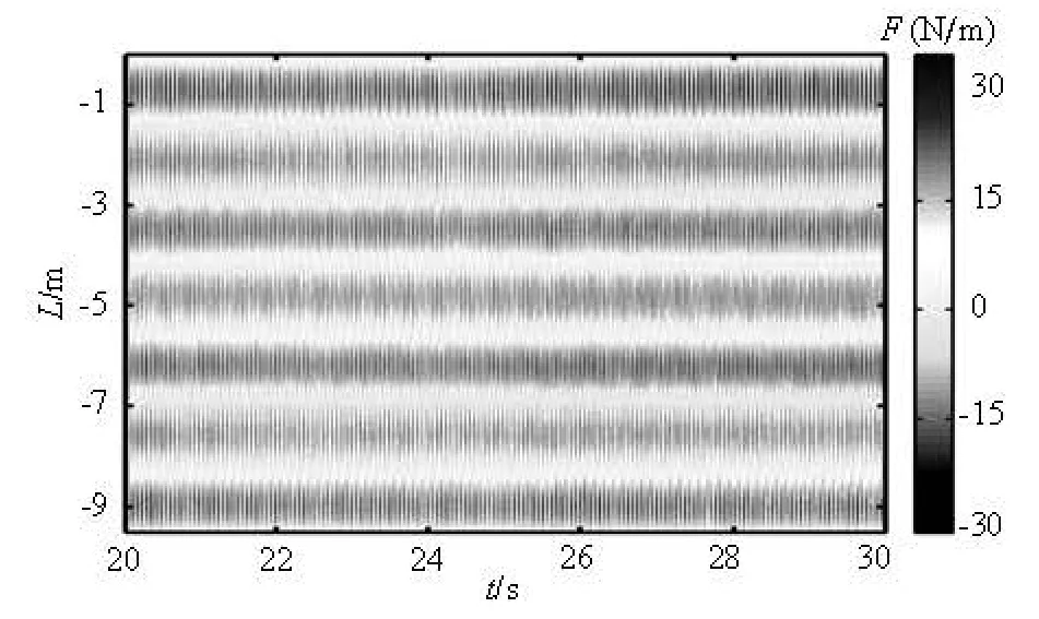
Fig.16 Contours of the in-line hydrodynamic force under uniform current,U =1.12 m/s

Fig.17 Added mass coefficient and amplitude ratio under uniform current,U =1.12 m/s
Figure 17 shows the added mass coefficients and the rms displacements in the cross-flow and in-line directions. The added mass coefficients are larger at the ends than those at other locations of the flexible riser. Both the added mass coefficients in the cross-flow and in-line directions fluctuate slightly along the riser. Using the improved formula for the added mass coefficient, the abnormally high values of the added mass coefficients as mentioned above do not occur where the responses are small. The amplitude of the crossflow added mass coefficient is about twice as large as that in the in-line direction. Similar phenomenon could be observed in the rms displacement response.
4. Conclusions
To estimate the hydrodynamic forces and the added mass coefficients, the VIV experiments are studied for a flexible riser under the excitation of a uniform current with the velocity of 1.12 m/s. It is concluded that the displacement responses under the uniform current are dominated by the standing wave and a single frequency in both cross-flow and in-line directions.
Methods with and without considering the influence of the interactions between adjacent elements are used to estimate the hydrodynamic forces along the flexible riser. The results quantitatively show that the estimation of the hydrodynamic forces using the finite element method considering the impacts from the adjacent elements is more accurate.
To elucidate the abnormally high value of the added mass coefficients at the locations where the response is small, an improved formula for the added mass coefficient is derived by applying the L'Hospital's rule at the positions of the flexible riser in which the small responses are found. Furthermore, the results of the added mass coefficients under the uniform current in the cross-flow and in-line directions also show a kind of three-dimensional effects.
Future research is recommended for the three-di mensional effects of the added mass coefficient and the relationship between the added mass coefficients and other parameters such as the non-dimensional frequency and the amplitude ratio.
[1] SARPKAYA T. A critical review of the intrinsic nature of vortex-induced vibrations[J].Journal of Fluids and Structures,2004, 19(4): 389-447.
[2] GABBAI R. D., BENAROYA H. An overview of modeling and experiments of vortex-induced vibration of circular cylinders[J].Journal of Sound and Vibra-tion,2005, 282 (3-5): 575-616.
[3] WILLIAMSON C. H. K., GOVARDHAN R. A brief review of recent results in vortex-induced vibrations[J].Journal of Wind Engineering and Industrial Aero-dynamics,2008, 96(6-7): 713-735.
[4] LARSEN C. M., VIKESTAD K. and YTTERVIK R. et al. VIVANA, theory manual[R]. MARINTEK Report, Trondheim, Norway, 2000.
[5] XU Wan-hai, WU Ying-xiang And ZENG Xiao-hui et al. A new wake oscillator model for predicting vortex induced vibration of a circular cylinder[J].Journal ofHydrodynamics,2010, 22(3): 381-386.
[6] HUANG Shan, SWORN Andy Some observations of two interfering VIV circular cylinders of unequal diameters in tandem[J].Journal of Hydrodynamics,2011, 23(5): 535-543.
[7] MA C. K., CHANG J. M. and LIN D. C. Input forces estimation of beam structures by an inverse method[J].Journal of Sound and Vibration,2003, 259(2): 387- 407.
[8] MAINCON P., BARNARDO C. and LARSEN C. M. VIV force estimation using inverse FEM[C].Proceedings of the ASME 27th International Conference on Offshore Mechanics and Artic Engineering.Estoril, Portugal, 2008, 673-681.
[9] JIE W., LARSEN C. M. and KAASEN K. E. A new approach for identification of forces on slender beams subjected to vortex induced vibrations[C].Proceedings of the ASME 27th International Conference on Offshore Mechanics and Artic Engineering. Estoril, Portugl, 2008, 779-788.
[10] ARONSEN K. H., LARSEN C. M. and MØRK K. Hydrodynamic coefficients from in-line VIV experiments[C].Proceedings of the 24th International Conference on Offshore Mechanics and Artic Engineering. Halkidiki, Greek, 2005, 783-791.
[11] VIKESTAD K.,VANDIVER J. K. and LARSEN C. M. Added mass and oscillation frequency for a circular cylinder subjected to vortex-induced vibrations and external disturbance[J].Journal of Fluids and Structu-res,2000, 14(7): 1071-1088.
[12] JIE W., LARSEN C. M. Hydrodynamic force identification from vortex induced vibration experiments with slender beams[C].Proceedings of the ASME 26th International Conference on Offshore Mechanics and Artic Engineering.San Diego, CA, USA, 2007, 753- 760.
[13] JIE W., LARSEN C. M. and LIE H. Estimation of hydrodynamic coefficients for VIV of slender beam at high mode orders[C].Proceedings of the ASME 29th International Conference on Offshore Mechanics and Artic Engineering.Shanghai, China, 2010, 557- 566.
[14] LIE H., KAASEN K. Modal analysis of measurements from a large-scale VIV model test of a riser in linearly sheared flow[J].Journal of Fluids and Structures,2006, 22(4): 557-575.
[15] RAO Z., FU S. and YANG J. et al. The application of non-sinusoidal mode shape function in the identification of modal weight[C].Proceedings of the ASME 29th International Conference on Offshore Mechanics and Artic Engineering.Shanghai, China, 2010, 931- 938.
[16] TOGNARELLI M., SLOCUM S. and FRANK W. et al. VIV response of a long flexible cylinder in uniform and linearly sheared currents[C].Offshore Technology Conference.Houston, USA, 2004, OTC16338.
10.1016/S1001-6058(13)60349-2
* Project supported by the National Natural Science Foundation of China (Grant No. 40906049).
Biography: ZHANG Hui (1984-), Female, Ph. D. Candidate
YANG Jian-min, E-mail: jmyang@sjtu.edu.cn

- 水动力学研究与进展 B辑的其它文章
- Critical size effect of sand particles on cavitation damage*
- Numerical simulation of rolling for 3-D ship with forward speed and nonlinear damping analysis*
- A new methodology for the CFD uncertainty analysis*
- The direct numerical simulation of pipe flow*
- Experimental study and finite element analysis of wind-induced vibration of modal car based on fluid-structure interaction*
- Simulation of wind-driven circulation and temperature in the near-shore region of southern Lake Michigan by using a channelized model*