
Numerical simulation of rolling for 3-D ship with forward speed and nonlinear damping analysis*
2013-06-01 12:29:57YANGChunleiZHURenchuanMIAOGuopingFANJu
水动力学研究与进展 B辑 2013年1期
YANG Chun-lei, ZHU Ren-chuan, MIAO Guo-ping, FAN Ju
State Key Laboratory of Ocean Engineering, School of Naval Architecture, Ocean and Civil Engineering, Shanghai Jiao Tong University, Shanghai 200240, China, E-mail: ycl229@163.com
Numerical simulation of rolling for 3-D ship with forward speed and nonlinear damping analysis*
YANG Chun-lei, ZHU Ren-chuan, MIAO Guo-ping, FAN Ju
State Key Laboratory of Ocean Engineering, School of Naval Architecture, Ocean and Civil Engineering, Shanghai Jiao Tong University, Shanghai 200240, China, E-mail: ycl229@163.com
(Received May 4, 2012, Revised August 16, 2012)
Strongly nonlinear characteristics of ship roll owing to viscous effect can be usually observed. To describe the nonlinear roll behavior, the CFD method has been frequently employed with obvious advantages compared with the traditional semi-empirical formula method in estimating the roll damping. Numerical simulations of free decay and forced rolling at various forward speeds and amplitudes for a 3-D ship hull are conducted in the present research to predict ship roll damping, in which a RANS solver is employed and a dynamic mesh technique is adopted and discussed in detail. Numerical results, including nonlinear flow characters around ships, rolling decay curves and damping coefficients, show that they are all in good agreement with available experimental data. The linear and nonlinear damping coefficients are estimated and analyzed by fitting with exponential functions for various rolling amplitudes, frequencies and speeds in the free decay simulations, and the damping coefficients are obtained by a polynomial fitting in the forced roll simulations. It is indicated that the damping coefficients increase with increasing rolling angle amplitude and velocity. It is also emphasized that the effect of forward speed is significant to roll damping and the nonlinear damping decreases with increasing velocity.
RANS method, free decay, forced roll, nonlinear damping
Introduction
Of all ship motions, accurate predictions of roll for operational and safety considerations are of paramount importance. Near resonance, a rolling ship can exhibit large-amplitude vibrations that may lead to capsize, cargo shift, loss of deck cargo and other undesirable consequences. However, the ability to predict roll motion accurately lags considerably behind that of motions such as heave and pitch. This is because, unlike other degrees of freedom, viscosity plays an important role in roll, especially in near-resonance cases. For example, turbulent, vortex-driven flows near the bilge of a ship significantly affect the evolution of roll motion, but this effect could not be accounted for by potential flow formulations.
The roll motion of ships is strongly related to viscosity effects and is extremely sensitive to viscosityinduced flow separations. While viscous forces and moments are of the first order for roll, they are only higher order for lateral-plane motions. The prediction of roll damping has been problematic for researchers and designers of ships. Prediction of roll damping has been mainly depended on semi-empirical formulas and physical tank tests for a long time. Generally speaking, roll damping is classified by wave damping, lift damping, friction damping, eddy making damping and bilge keel damping. Only the wave damping may be obtained based on assumptions of potential flow theory. Other components of roll damping are determined by empirical formulas or experiments. Ikeda et al.[1]developed an empirical method to predict the roll damping according to a series of model experiments. Based on the continuing studies on the roll damping prediction of ships, Ikeda applied the method to improve accuracy, extended their applicability to determine optimum size and location of bilge keels[2]. Bothfree roll decay and forced oscillation experiments were carried out in calm water and in waves, over a range of forward speeds, and the mechanisms of roll damping around a conventional combatant hull form and an advanced tumble-home hull form were well understood by the systematic series of model tests[3]. Results of roll predictions in time domain based on potential flow[4,5]were partially dependent on empirical roll damping data which was limited to the pertinence relation of frequency and ship form. Numerical methods are in urgent need for simulations of viscous flow and larger amplitude motions of surface ships.
Investigation on the area of resistance and powering with the RANS method is comparatively mature. However, the prediction of maneuvering and seakeeping seems a relatively new area based on the RANS computations. 2-D roll simulations of RANS may accurately predict both the magnitude and phase of the measured data as well as the highly oscillating variations in the force data. The flow feature of the convection of the vortex, the production of vortices and the position of the vortex core are described. 2-D hydrodynamic coefficient has been predicted accurately[6-8]. The RANS computations of 2-D roll motions were limited in describing roll motion due to the strong dependence on forward speed. A current effort by Miller et al.[9]demonstrated the RANS simulations of roll motion for a 3-D cylinder, including bilge keels, with and without forward speeds. The simulation results successfully predicted the roll resonance when the incident wave frequency coincides with the free decay frequency of the barge[10]. Wilson and Stern[11]accurately predicted the natural rolling frequency and roll decay rate at multiple ship speeds without bilge keels based on the SFDSHIP-IOWA solver. From these computations the RANS shows promise for predicting roll motions, but more evaluation and further research need to be performed, particularly for roll decay.
The present study concentrates on nonlinear time-domain simulations for free decay and forced rolling motions based on CFD. Furthermore, for free decay roll and forced roll, linear and nonlinear coefficients are estimated by fitting with exponential functions and a polynomial fitting respectively. The influence of amplitude and frequency and the importance of the forward speed effect on rolling damping are discussed in detail.
1. CFD method
1.1 Numerical method
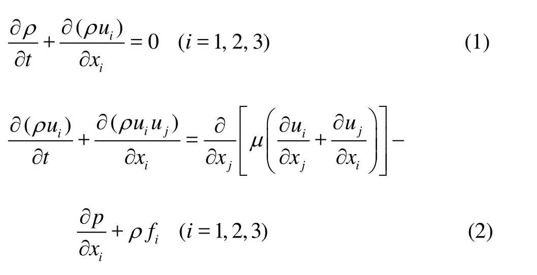
Time-domain simulations for 3-D ships are performed with the platform of the commercial software Fluent. A RANS solver is employed to solve incompressible flow and the advection terms are discredited by a second order scheme. The VOF method is used to track the free surface. The governing equations can be written as:
The VOF method is adopted to capture the free surface deformation, and the equations can be written as:

where q =1 and 2 denote the air phase and the water phase, respectively.
The momentum and continuity equations are coupled through the Pressure Implicit Split Operator (PISO) algorithm. The turbulence model in the present simulations is the classical 2-equation eddy viscosity model, i.e., Menter’s Shear Stress Transport (SST) k-ωmodel. For temporal discretization, a second-order accurate difference scheme is used. For[12]spatial discretization, a third order up-wind difference scheme and a central difference scheme are applied.
1.2 Ship motions and the dynamic mesh method
An inertial coordinate system is adopted. Inflow velocity at the inlet boundary represents forward speed of the ship in the positive direction of x axis and also the roll axis. The roll axis passes through the Center of Gravity (CG) and is parallel to the calm waterline. The ship motions in the inertial reference frame are expressed as:
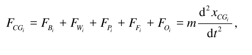

where xCGiand θCGiare translations and rotations of the ship, while FCGiand MCGiare the resultant forces and moments acting at the CG of the ship for thei -th mode of motion.FBi,FWi,FPi,FFi,MBi, MWi,MPiand MFiare the element forces and moments due to buoyancy, weight, hydrodynamic pressure and friction, respectively.FPi,FFi,MPiand MFicould be computed by integrating on instantaneous wet surface when the governing equations are solved.FOiand MOiare the external force and moment for the forced motions. Ship motions may be categorized by six modes which represent surge, sway, heave, roll, pitch, and yaw while i =1-6, respectively. However, the ship model is free to roll about the roll axis and other rotation and translation are restrained. The original position of the CG is set to match the equilibrium of buoyancy and gravity.
In this work, the CFD mesh is moved at each time step in order to adapt the ship rolling motion. In the iterative step, the roll angle θtat the current time levelt is expressed by a first order Euler explicit format,

where θ,θ˙andθ˙˙are roll angle, velocity, and acceleration, respectively,Δtis the time step.
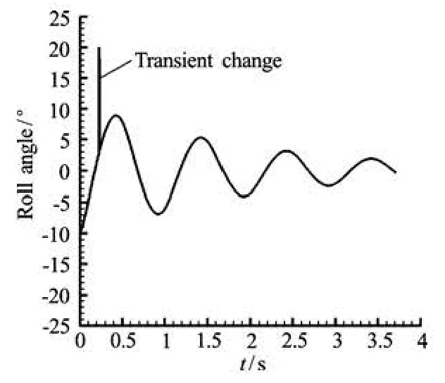
Fig.1 Example for transient effect of simulations
The transient change of results due to the iteration errors may cause numerical instability, as shown in Fig.1. In order to improve the iteration stability, conception of relaxation parameterω here is introduced for deducing the “fake motion”.

Numerical accuracy can be improved by using a third order implicit format which is defined by Eq.(8). The ship position and angular velocity predicted by Eq.(6) can be corrected by Eq.(8) to estimate the resultant force and moment more accurately at the time step level. The dynamic mesh is realized by solving Eqs.(6), (7) and (8). The six-DOF motion program is based on secondary development and compiled as a User Defined Function (UDF) on the Fluent platform. Figure 2 shows the procedures of the ship motion computations.


Fig.2 The procession chart of the ship motion calculation
2. Nonlinear roll damping
2.1 Free decay motions
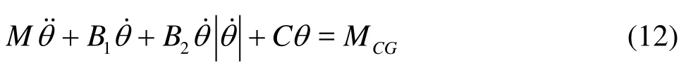
The basic equation to describe the free rolling motion of ships may be written as
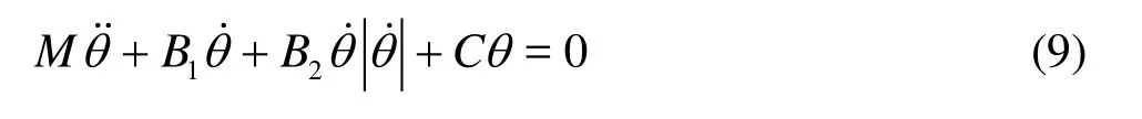
where M includes the ship inertial moment and the added inertial moment for rolling,B1and B2are the linear and quadratic roll damping coefficients, and C is the ship restoring coefficient.
The damping coefficients are estimated by a relationship of energy dependence,

where b1and b2are derived through a least square fitting on the data points of the extinction test curve shown in Fig.3.
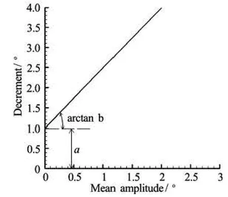
Fig.3 Example of decay decrement

Table 1 main particulars of Model 5512 and Series 60
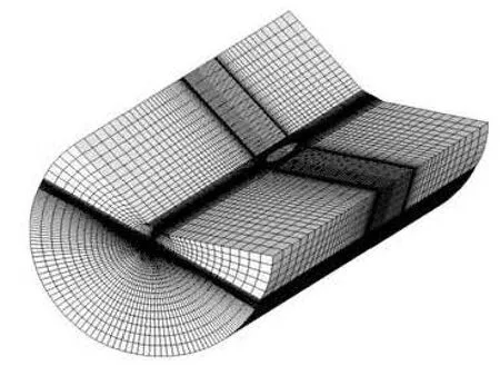
Fig.4(a) 3-D CFD mesh around ships
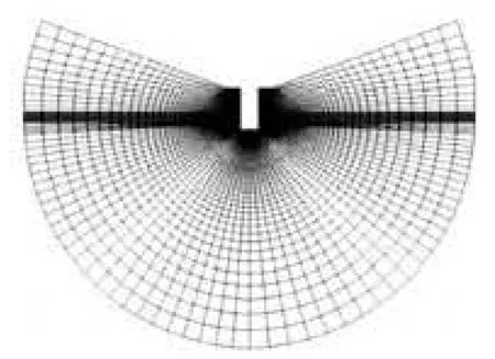
Fig.4(b) Original mesh
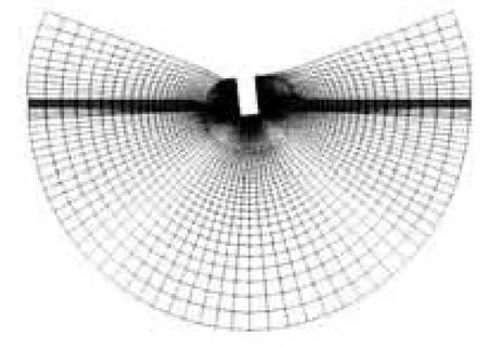
Fig.4(c) Deformed mesh
The decrement δkfor the k -thoscillation is expressed as

where θkis the average amplitude at the k-th oscillation period. In order to solve the roll motion equations simply,B2is linearized generally as

where Beis the equivalent damping,θAis the roll amplitude, and ωdis the natural roll frequency.

Fig.5 Roll decay at low speed

Fig. 6 Roll decay at medium speed
2.2 Forced roll motions
The basic equation to describe the free rolling motion may be written as

Table 2 Comparison of calculated and measured results
where the moment coefficient MCGis the time history of the computed moments, and is fitted with

by applying the Fourier analysis,G0and G1are the amplitudes,αandβare the phase angles.
The damping coefficients can be derived by a polynomial fitting. The nonlinear term B2can be linearized by introducing an equivalent damping. The results from the experiments and simulations are made dimensionless as follows:

whereB is the beam length of the ship.
3. Geometry and computational grid
Simulations for the Model 5512 and Series 60 ship form are carried out, whose main particulars are given in Table 1. The Model 5512 is a modern naval combatant with sonar dome and transom stern and has been selected by SIMMAN 2008 and Gothenburg 2010 workshop on CFD in ship hydrodynamics as a benchmark. The measurements of roll decay motion were performed at IIHR[13]. The experimental data for the motion of Series 60 in Ref.[14] have been used to validate the damping coefficients. The experimental data such as inertia and damping coefficients for 2-D and 3-D cases of rolling cargo ships were obtained from Ref.[1]. The principal dimensions of the model are shown in Table 1.
Simulations of free roll decay are performed in calm water for Model 5512 without appendages. The experimental dates are provided for a range of forward speeds and initial roll angles[13]. Forced roll motions are simulated at different amplitudes and frequencies for Series 60.
The 3-D structural mesh given in Fig.4(a) is generated for the whole domain and is refined around the free surface and the hull. The mesh around ships consists of 1.5×10⁶cells. The mesh is divided into two domains to accommodate the roll motion. A spring smoothing method is used to describe the motion of the two domains connected with a spring. The nodal position adjusts as required until an equilibrium is reestablished as shown in Figs.4(b)and 4(c). The internal domain is cylindrical and rotate rigidly following ship motions and the external domain is deformed wellproportionally.
4. Results and discussion
4.1 Roll decay
In the roll decay simulations, the model is brought to an initial angle of 10ofrom the equilibrium position, and is adjusted by changing the lognormal gesture in order to match the test condition. Two cases are investigated in CFD simulations at medium speed (Fr =0.28)and low speed (Fr =0.138). The ship is kept at the steady speed and the initial roll angle in the initial stage (0 s-4 s). In the second stage (4 s-17 s) the model is released to roll freely.
Figures 5 and 6 show the time history of roll decay and the comparison with the available experimental data. The decay period Tdis estimated approximately during the first three cycles. Roll angles reduce rapidly at the beginning of the decay, and a very small decay is generated at the last cycles, as shown in Figs.5 and 6. The linear dampingis estimated from the last five cycles because of the weak nonlinearity. The non-linear dampingis derived from the first three cycles due to stronger nonlinearity. The results are summarized in Table 2.
Table 2 shows that the natural period is overestimated by 1.3% for the low speed case. The predicted value for the medium speed case is about 2.5% shorter than the measured one. It is noted that the uncertainty of the measured results lead to the discrepancies, at least in part. Roll damping increases with increasing the velocity. The linear and equivalent linear damping produce the value of, and the results indicatethat a significant increase in the proportion of linear damping with increasingFr . The forward effect is obvious to the roll damping.
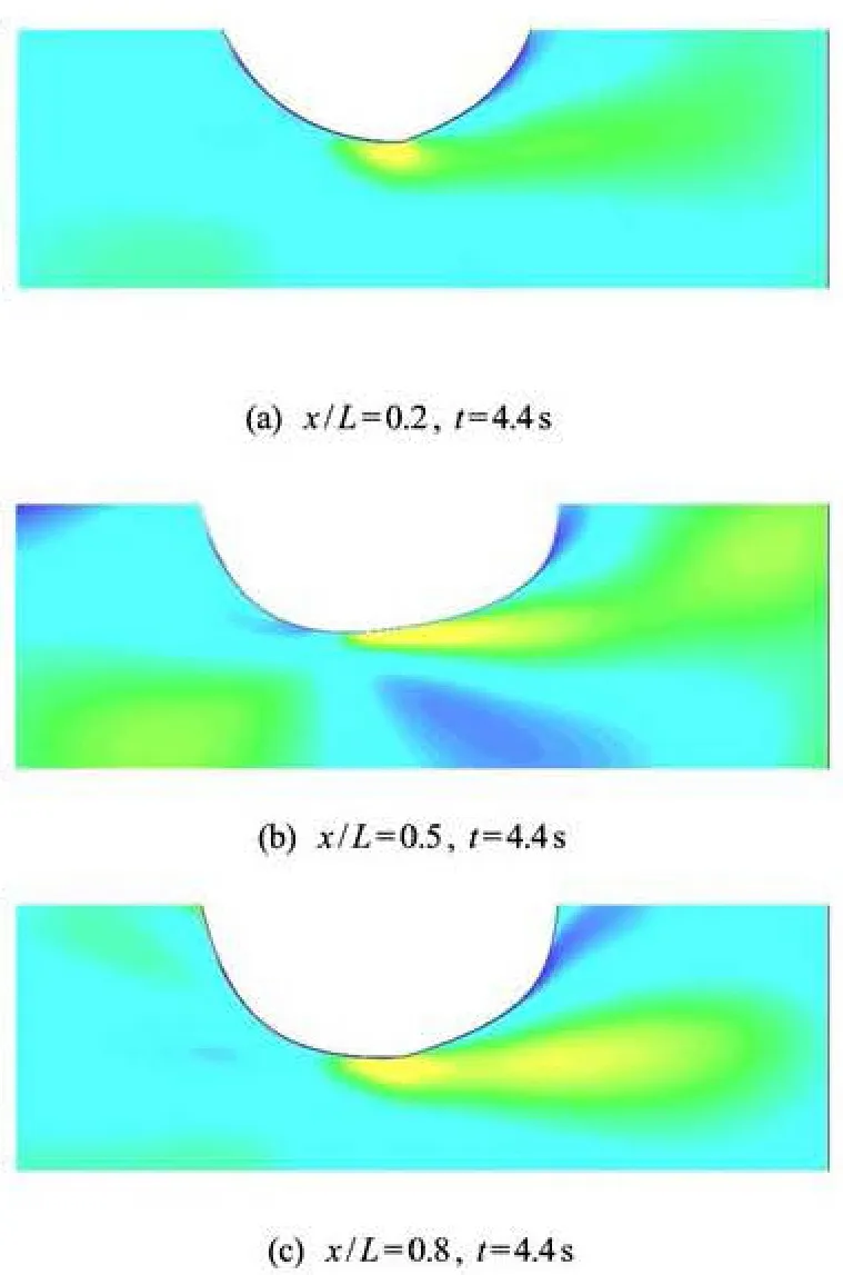
Fig.7 Velocity contours at the equilibrium position
Flow behavior around the model is investigated by the simulation. In Fig.7, the velocity field at x/ L =0.2, 0.5 and 0.8 are shown and provide a detailed assessment of roll damping at Fr =0.28. It is clear that a stronger vortices are detached from the mid ship plane than that from the bow plane. The viscous eddy damping for a bare hull arises due to the vortices generated by the flow separation which is caused by pressure variation on the hull. The flow separates at the bottom of the ship near the stem and stern and at the bilge circle near the midsection.
4.2 Forced roll
In order to study the effects of the frequency relativity, amplitude and forward speed on the roll damping, forced roll simulations are performed. The computed pressure and shear stress are integrated around the hull and the component of roll moment is investigated. The roll time history is prescribed by
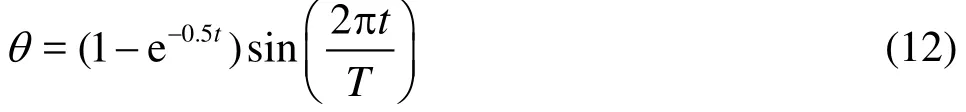
During the first two periods, the amplitude is increased gradually to the maximum. The forced roll simulations with pre-oscillations shown in Fig.8 can lead to realistic damping values.
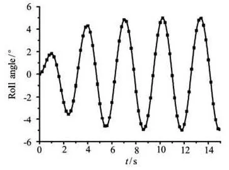
Fig.8 Time history of roll angle
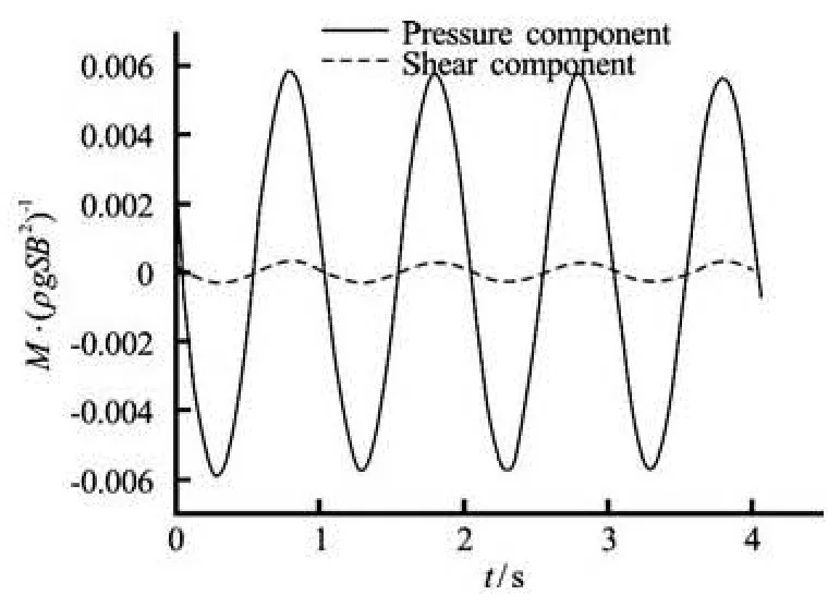
Fig.9 Time history of pressure and shear component

Fig.10 Time history of roll moment
It is seen from Fig.9 that the pressure component is dominated in the total roll moment at the initial roll angle of 5oand the period of 1.0 s. A similar behavior has been reported by Sarkar and Vassalos[6]. The roll moment shown in Fig.10 is used to predict the linear and nonlinear damping coefficients with the method described in Section 2.2.
The total roll damping in the empirical formula method and linear potential theory is divided to the five damping terms as was discussed in Introduction. Seakeeping software based on the above formulation estimates the roll damping coefficients. However, for any such empirical method, the formulas are based on experimental data for particular ship shapes and the generalization to all shapes may pose some problems. From this point of view, CFD methods can reflect thenonlinear characteristics and exhibit their advantages compared with the diffraction/radiation method. Results by CFD calculations (elaborated in Section 2.2) and empirical formulas are listed as shown in Figs.11-14. A more detailed description of the formulas is given in Ref.[15].

Fig.11 Roll damping coefficient at Fr =0(θ0=5o)
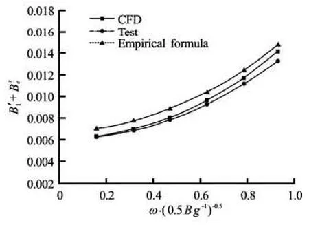
Fig.12 Roll damping coefficient at Fr =0.2(θ0=5o)
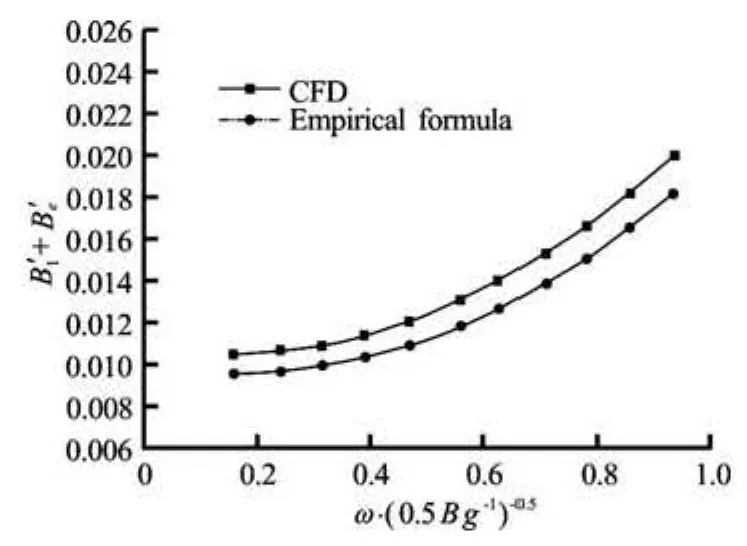
Fig.13 Roll damping coefficient at Fr =0(θ0=10o)
Figures 11-14 illustrate the variation of total linear damping with frequency. The influence of the forward speed is well captured. The results show slight variation in the low-frequency range but significant increase with frequency is shown in the high-frequency range. This is consistent with the conclusion of Ikeda et al.[16]. It can be seen that forward speed has a significant effect on the roll damping. The roll damping increases by a factor of 1.2 to 2.5 for the Froude number from Fr =0to Fr =0.28. The simulated results show good agreement with experiments in the range of medium to high frequency, while the damping is overestimated in the low-frequency range as shown in Fig.11. Dedicated discussion by Taylan[17]focused on the effect of forward speed on ship rolling damping, and a similar conclusion was reached. By the present empirical formula method for roll damping estimation[15], the 2-D sectional coefficients are integrated over the length of the ship for a 3-D ship form, and the damping is modified with the forward speed. Thus the calculation of sectional damping coefficient only considers the section geometry of the ship along its length. The CFD method can reflect the 3-D effect of hulls of finite length and make the damping values more realistic compared with modifications for the forward speed.
Fig.14 Roll damping coefficient at Fr =0.2(θ0=10o)
Fig.15 Pressure contours for Model S60 rolling at θ0=5o
Figure 15 shows the computed hull surface pressure contours to illustrate the complex 3-D flow features induced by the forced roll motions. A larger roll damping is near the midsection and causes flow separation and large resistance to the roll motions. If finer mesh is employed, more flow details can be obtained.
5. Conclusions
As is well known, viscosity plays an important role in ship motions. Numerical simulation of ship moving in water should take into account the viscous effects, especially for rolling motion simulation. Now simulation of ship model rolling in calm water is feasible, however, the full-scale ship rolling in calm water and six DOF simulations for ships advancing in a sea state still encounter difficulties due to the heavy time-consumption and computer resources by CFD approaches.
In the present paper, a RANS method with the dynamic mesh technology is employed to simulate both the free decay and forced roll motions in calm water. It is demonstrated that the approach is effective to calculate the nonlinear and linear roll damping for various ship models. The simulation process and the detailed description of the fluid flow field around a ship is benefit for researcher to have a deep insight into the complex phenomena. The influences of forward speed, roll amplitude and frequency on the ship roll damping are evaluated. The results are analyzed by both linear and nonlinear damping components decomposition method. It is useful to predict ship rolling in a sea state.
For free decay cases, the natural periods of ship model advancing at different speeds are calculated with an error of 1.3%-2.5%. The characteristic of vortex due to the flow separation is shown clearly. Linear and quadratic roll damping coefficients are calculated based on a local fitting with exponential functions between adjacent cycles. The proportion of the nonlinear damping decreases with the increasing speed.
For the forced roll cases, the damping coefficients are derived by a polynomial fitting according to the roll moment data that are in good agreement with the experimental results. The value of damping changes significantly with the frequency increasing. The damping coefficient intensively depends on the amplitude and frequency of ship roll. The viscosity method shows better performance than semi-empirical formula by taking ship body 3-D effect and speed influence into account.
[1] IKEDA Y., HIMENO Y. and TANAKA N. On eddy making component of roll damping force on naked hull[J].Journal of the Society of Naval Architects ofJapan,1977, 142: 54- 64.
[2] IKEDA Y. Prediction methods of roll damping of ships and their application to determine optimum stabilization devices[J].Marine Technology,2004, 41(2): 89-93.
[3]ATSAVAPRANEEP.,CARNEAL J. B. andGRANT D. et al. Experimental investigation of viscous roll damping on the DTMB Model 5617 hull form[C].The 26th International Conference on Offshore Mechanics and Arctic Engineering.San Diego, California, USA, 2007, 4: 561-570.
[4] LI Yi-le, LIU Ying-zhong and MIAO Guo-ping. Potential flow solution using higher order boundary element method with Rankine source[J].Journal of Hydro-dynamics, Ser. A,1999, 14(1): 80-89(in Chinese).
[5]PU Jin-yun, ZHANG Wei-kang and JIN Tao Melinikov’s method for non-liner rolling motions of a flooded ship[J].Journal of Hydrodynamics, Ser. B,2005, 17(5): 580-584.
[6] SARKAR T., VASSALOS D. A RANS-based technique for simulation of the flow near a rolling cylinder at the free surface[J]Journal of Marine Science andTechnology,2000, 5(2): 66-77.
[7] YU Yi-Hsiang and KINNAS SPYROS A. Prediction of hydrodynamic performance for various ship-shaped hulls under excessive roll motions using an unsteady Navier-Stokes solver[C].Proceedings of the 18th International Offshore and Polar Engineering Confe-rence.Vancouver, Canada, 2008.
[8] HUANG Hao, GUO Hai-qiang and ZHU Ren-chuan et al. Computations of ship roll damping in viscous flow[J].Journal of Ship Mechanics,2008, 12(4): 568-573.
[9] MILLER R., GORSKI J. and FRY D. Viscous roll predictions of a circular cylinder with bilge keels[C].Proceedings of the 24th Symposium on Naval Hydro-dynamics.Fukuoka, Japan, 2002.
[10] CHEN H.-C., LIU T. Time-domain simulation of large amplitude ship roll motions by a Chimera RANS method[C].Proceedings of the 11th International Offshore and Polar Engineering Conference.Stavanger, Norway, 2001, 299-306.
[11] WILSON R., STERN F. Unsteady RANS simulation of a surface combatant with roll motion[C].Proceedings of the 24th Symposium on Naval Hydrodynamics.Fukuoka, Japan, 2002.
[12] STEPHEN B. P.Turbulent flows[M]. Cambridge, UK: Cambridge University Press, 2000.
[13] IRVINE M., LONGO J. and STERN F. Towing-tank tests for surface combatant for free roll decay and coupled pitch and heave motions[C].The 25th Symposium on Naval Hydrodynamics.St. John’s, New- foundland and Labrador, Canada, 2004.
[14] VUGTS J. H. The hydrodynamic forces and ship motions in waves[D]. Doctoral Thesis, Delft, The Nether- lands: Delft University of Technology, 1970.
[15] CHAKRABARTI S. Empirical calculation of roll damping for ships and barges[J].Ocean Engineering,2001, 28(7): 915-932.
[16] IKEDA Y., ALI B. and YOSHIDA H. A roll damping prediction method for a FPSO with steady drift motion[J].Proceedings of the 14th International Conference Offshore and Polar Engineering.Toulon, France, 2004, 676-681.
[17] TAYLAN M. Effect of forward speed on ship rolling and stability[J].Mathematical and Computational Applications,2004, 9(2): 133-145.
10.1016/S1001-6058(13)60348-0
* Project supported by the National Natural Science Foundation of China (Grant No. 50639020), the National High Technology Research and Development Program of China (863 Program, Grant No. 2006AA09Z332).
Biography: YANG Chun-lei (1982-), Male, Ph. D. Candidate
ZHU Ren-chuan, E-mail: renchuan@sjtu.edu.cn

- 水动力学研究与进展 B辑的其它文章
- Critical size effect of sand particles on cavitation damage*
- Hydrodynamic performance of flexible risers subject to vortex-induced vibrations*
- A new methodology for the CFD uncertainty analysis*
- The direct numerical simulation of pipe flow*
- Experimental study and finite element analysis of wind-induced vibration of modal car based on fluid-structure interaction*
- Simulation of wind-driven circulation and temperature in the near-shore region of southern Lake Michigan by using a channelized model*