高压电网电流互感器饱和对继电保护的影响应用分析与研究
王志华
(广东电网公司珠海供电局,广东珠海 519000)
For the ultra high voltage system with 220 kV and above,in-depth research has been conducted on currenttransformer saturation’effects on relay protection especially on differential protection and a series of effective measures in increasing current transformer saturation ratio and improving the antisaturation capability of relay protection device have been put forward.While for the low voltage system(lower than 110 kV),it wasn’t given enough attention for the reason that due to the short circuit’s small capacity and big impedance in middle-low voltage system,short circuit current usually can’t reach the current transformer saturation level.But with the reform of urban and rural grid,current transformer saturation problems have become increasingly promi nent in middle-low voltage system,which has affected the action accuracy of power-off protection device and posed a threat on safe operation and supply reliability of the grid.Take Figure 1 as an example,due to the replacement of main transformer and the reconstruction of upper grid,the short-circuit current of 10 kV side in substation transformer reaches 40.4 times of the rated current of current transformer.
On December 15,2007,in a 220 kV substation,the high voltage side of a 10 kV grounding transformer was short circuited,grounding transformer protection failed to work for current transformer saturation.Electromagnetic over-current relay in section 1 of main transformer backup protection got stuck and failed to work for the large short circuit current and movable contact went too far,section 2 of main transformer backup protection tripped and made all the transformers stop operation.According to the fault recorder data analysis,short-circuit current reached 50 times of transformer’s rated current at the high voltage side of grounding transformer.
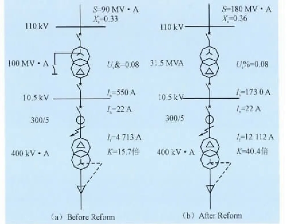
Fig.1 System parameters before and after system Reform
1 Causes of Current Transformer Saturation
The essential cause of current transformer saturation is that the overlarge excitation current makes the working flux density surpass the iron core saturation flux density.
For a certain current transformer,the increase of short circuit current will cause iron core saturation.The main causes of short circuit current increase are:
1)increase of main transformer’s capacity;
2)the reform of upper grid reduces the system’s equivalent impedance;
3)increase of system equivalent short-circuit capacity.
For a certain system,short circuit current is fixed.The main causes of current transformer saturation are:
1)rated current in primary side of the current transformer is too small;
2)load in secondary side of the current transformer increases;
3)transformer rated flux density is too high.
2 Characteristicsofsecondarycurrent in current transformer saturation
The transfer characteristics of current transformer in saturation has been analysed in detail in literatures[1-4].Figure 2 shows the current waveform of primary and secondary current during serious current transformer saturation in literatures[1-2].
Omit the complicated theoretical analysis and numerical calculation,the secondary current in Figure 2 has following characteristics:
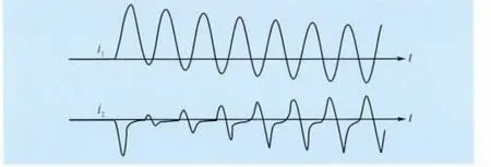
Fig.2 Current waveform of primary and secondarycurrent in serious current transformer saturation
1)In the initial 1/4 cycle after short circuit,current transformer can transfer basically and the error is small;
2)Under the combined action of short circuit current’s DC component and residual magnetism,the iron core becomes saturated in less than half cycle after short-circuit;
3)the residual current waveform in secondary side is exponential decay according to time constants of current transformer’s secondary side in current transformer saturation;
4)when the current crosses zero,due to the demagnetization effect,current transformer resumes transmission until be saturated again;
5) When primary current’s DC component is ignored,saturation point of secondary current(saturation angle θ)can adopt the inverse sine approximation algorithm.
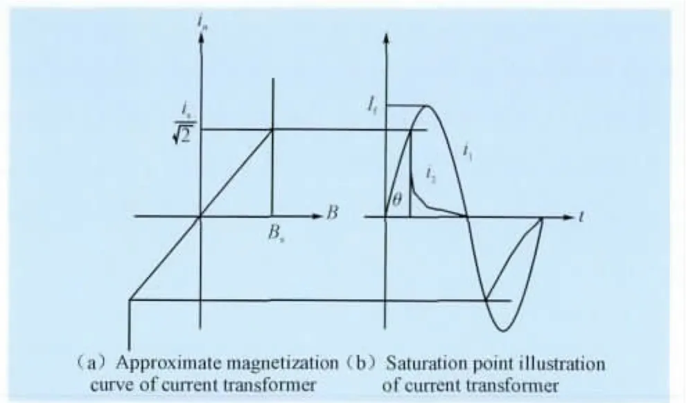
Fig.3 Illustration of current transformer saturation point calculation

As current protection is the main protection in mid-low voltage system,in the next we’ll analyze current transformer saturation’s effects on current relay.
3 Current Transformer Saturation’s Effects on Electromagnetic Relay
In electromagnetic relay,the currentforms magnetic flux to generate a torque or suction.When the torque or suction is greater than the gravitation,the relay starts operation.
3.1 Inductive current relay

For inductive relay,when its magnetic circuit is unsaturated,the equivalent operating characteristic can be expressed approximately as where,Ikmeans short-circuit current flowing into inductive relay;I∞means equivalent braking current to friction force of inductive relay;A means setting value of inductive relay’s operating characteristics,which is equivalent to rising distance of sector wheel.
When transformer is saturated,neglects rotating torque differencesofevery harmonic wave,the equivalent short-circuit current is:

The saturated operating time can be expressed by unsaturated operating time and saturation angle with statement(3)and Figure 4.
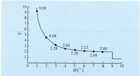
Fig.4 Relation between operating time ratio and saturation angle of inductive current relay

3.2 Electromagnetic current relay
The equivalent operating criteria is:

where,IJmeans short-circuit current flowing into electro-magnetic relay;IPmeans Operating Current equivalent to spring tension and friction coefficient
According to statement(2),when transformer becomes saturated,the equivalent operating current in its secondary side becomes smaller,which is shown in Figure 5.As long as equivalent operating current is larger than the setting value,the electromagnetic relay is able to act.
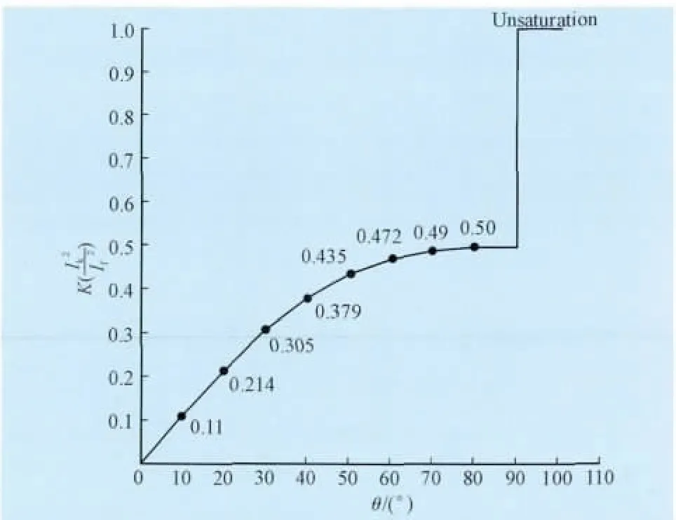
Fig.5 Relation between operating equivalent operating current factor and saturation angle of electromagnetic current relay
4 Current Transformer Saturation’s Effects on Analog Relay
According to the realization methods,analog relays can be classified into transistor type and integrated circuit type.While according to operating principles,they can be divided into peak comparison and mean value comparison type.
4.1 Peak comparison current relay

Fig.6 Diagram of peak value comparison current relay
Peak value comparison relay compares rectified pulse with triggering level,when the time of peak current reaching triggering level surpasst,relay operates.The purposes of introducing t are:
1)anti-interference;
2)reducing the dispersion of operating value.Obviously,if t≥5 ms,the relay fails to operate after current transformer saturation,if t meets:

where,IPmeans setting operating current of relay;Ifmeans secondary value of short-circuit current if transformer is unsaturated;θ means saturation angle of short-circuit current,then peak comparison relay can operateaccurately.
4.2 Mean value comparison relay

Fig.7 Mean value comparison relay diagram
If power frequency band-pass filter is not adopted in the mean value comparison type current relay,the factor k of current detected between transformer saturated and unsaturated is:

According to statement(6),when transformer becomes saturated,its equivalent current in secondary side became smaller,as Figure 6 shows.As long as equivalent operating current is larger than the setting value,mean value comparison relay still can operate.
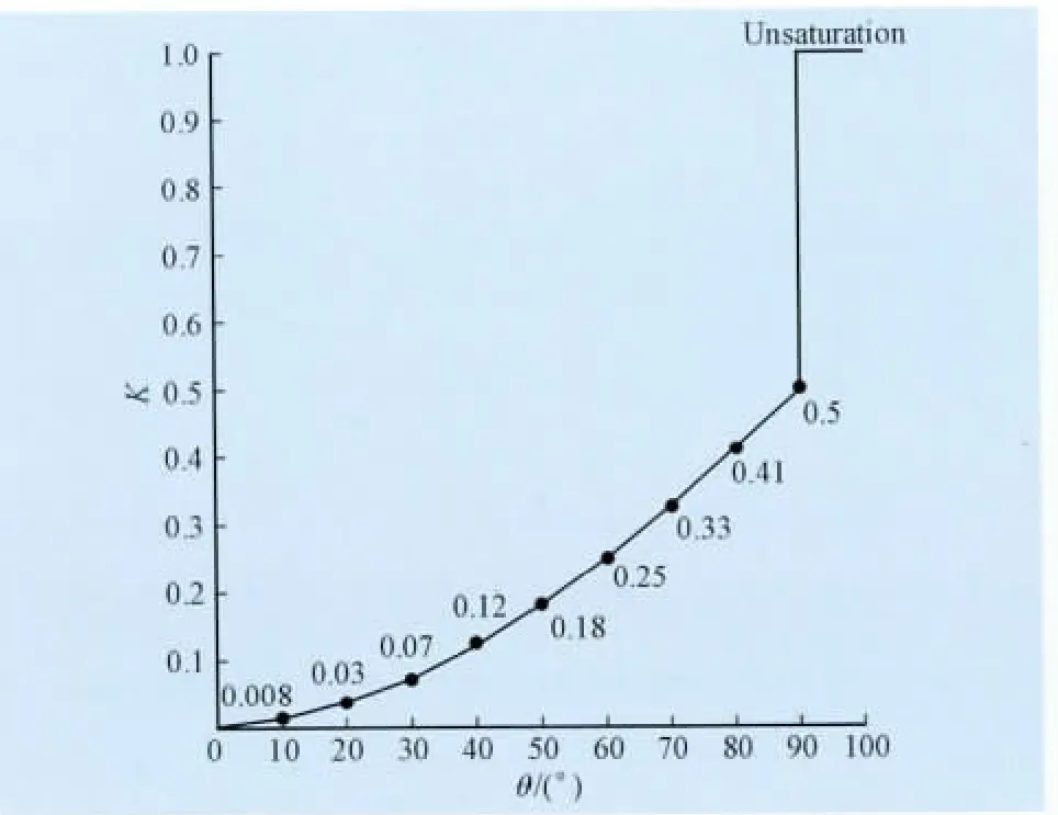
Fig.8 Relation between equivalent operation current factor and saturation angle of mean value comparison relay
However,analog relay are active relay,the processed signal level is restricted by its device source.When the input current is overlarge,truncated saturation phenomenon occurs inside the relay.If internal relay level of the operating current setting valuereachesorexceedshalfofthe truncated saturation level inside the relay,then it will refuse to operate.
I power frequency band-pass filter is adopted,first we need to put the saturated current in the form of Fourier series as statement(7),then restore it into time-domain waveform afterfiltration forfurther analysis.
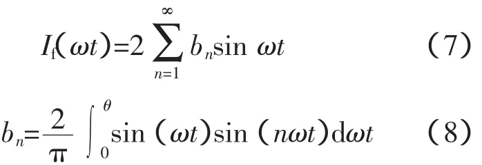
The calculation progress is omitted here.The existence of power frequency filter has reduced the function oflow orderhigh-frequency component,which decreases the equivalent operating current factor and increases the possibility of relay’s refusing operation.
5 Current Transformer Saturation’s Effects on Digital Relay
Digital relay works by microcomputer(usually single chip).For its main working source is 5 V and working range of data collection is only 10 V,the signal range it can effectively deal with is smaller and transformer’s saturation’s effect on digital relay is larger.
5.1 Influence on Auxiliary Criterion
In some microcomputer protection,IA+IB+IC=3I0(produced zero sequence equals external connected zero sequence)is adopted as the auxiliary criterion of disconnection and data collection circuitfailure,which is quite an effective block measure for normal operation.However,when failure occurs and transformer becomes saturated,the relay will also be blocked and refuse to act.
5.2 Influence on Fundamental Frequency Component Algorithm
As digital filter has excellent filtering capability and most algorithms(e.g.DFT algorithm)have good filtering function,the operating quantity in microcomputer protection is mostly limited to fundamental frequency component.
During transformer saturation,fundamental frequency component is related to the saturation angle and can reach half of the fault component at most.If the setting current is higher than half of the maximum current the microcomputer can deal with,the relay will refuse to act certainly.
5.3 Influence on Different Data Acquisition Methods
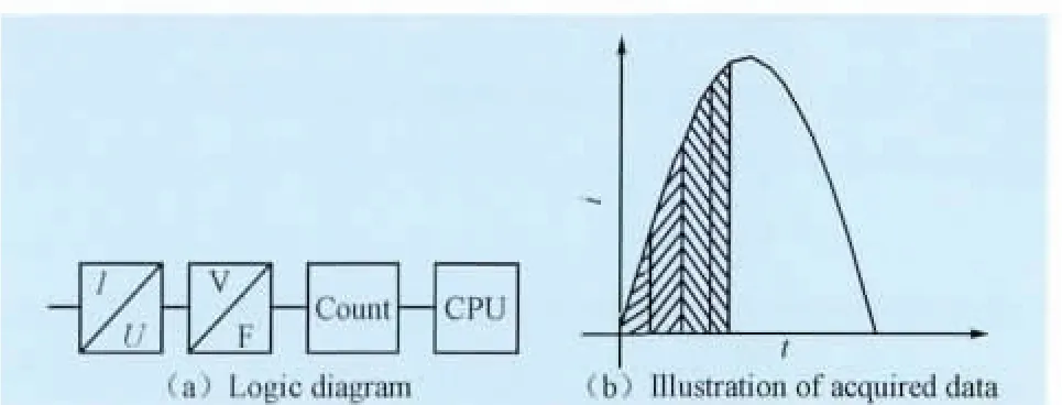
Fig.9 VFC and A/D conversion diagram
In microcomputer protection,there are two typical methods in data acquisition:VFC method and A/D method.
As VFC method has integral function which is equivalent to a first-order low-pass, it’s not necessary to adopt front analog low pass filter.Data acquired by VFC method is the mean value of signal in two reading intervals.If the input signal is larger than VFC maximum conversion level,it’ll cause truncated saturation.
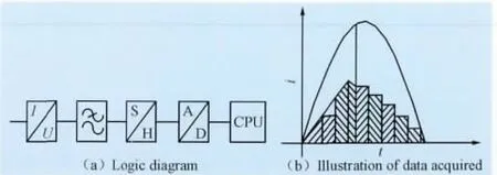
Fig.10 Data collection method by A/D
In data collection using A/D method,the front analog low pass filter is needed to avoid frequency aliasing.If the filter is passive,as there is no truncated saturation problem,wave width of saturation waveform becomes wider and its range becomes lower afterlow-passfilter,which ishelpfulfordata acquisition.Data acquired by the A/D method is instantaneous value of signal after low-pass filter at acquiring point.
Either by VFC or A/D method,in order to correctly acquire saturation current waveform,specific sampling rate must be guaranteed.It’s also the same in the protection with improved algorithm.Suppose that effective continuous data point for valid criterion is N,current saturation angle is θ,sampling frequency is fS/H(Hz):

If 5 successive fault current data is needed to make reliable operation in protection algorithm and currentsaturation angle is 60°,the sampling frequency must be up to 1800 Hz which means to get 36 point sampling per cycle,which is difficult and uneconomic for protective device in mid-low voltage power system.
A better method is taking zero sequence overcurrent as additional protection when transformer becomes saturated (of course we can use zero sequence over-current as the main protection criterion despite of the complicated setting calculation).
6 Measures for Anti-saturation of Current Transformers
6.1 Restricting short circuit current
Primary system should take effective measures to restrict the sustained increase of short circuit current and eliminate the cause ofcurrenttransformer saturation fundamentally.
6.2 Increasing the transformation ratio of current transformer
Increasing the transformation ratio of current transformer can make it adjust to larger short circuit power source and stay unsaturated.If the maximum short circuit current at current transformer installation point is Ifmax,current transformer’s saturation ratio is KS(if this data is unavailable,10%error ratio can be used instead which is safer),the primary rated transformer current:

Take the system in Figure 1 as example,the 10%error ratio of selected current transformer is 15,then

So the transfor mation ratio of selected current transformer is 800/5A.
But increasing transformation ratio of current transformer will bring side effects for relay protection device.Take the system in Figure.1 for example again,the rated operating current at high voltage side of the transformer is only 22 A.For the originally chosen current transformer(300/5),the working current at secondary side is only 0.367 A.If 800/5 power transformer is adopted,rated current at secondary side is only 0.137 A,which forces the protection device work in low current and it’s unfavorable for precision and anti-jamming performance of protection device.
6.3 Strengthening current transformer’s antisaturation capability
It’s necessary to develop new current transformer with higher anti-saturation capability,for example,use the iron core with small air gap.
6.4 Strengthening relay protection device’s antisaturation capability
Because there are many causesforcurrent transformer saturation,it’s rather difficult to avoid saturation completely,it’s quite necessary for relay protection device to have better anti-saturation capability.
6.5 Choosing current transformer and relay protection device reasonably
Choosing current transformer and relay protection device reasonably can improve the anti-saturation level of entire system.
In choosing current transformers,those with large saturation ratio(or 10%error ratio)and strong carrying capacity is more preferred.The measuring current transformer requires accuracy in normal operation,but the protective current transformer requires accuracy in short duration.It’s difficult to put these two properties together by existing technology.So we should try to avoid choosing the current transformer with both measurement and protection function.
Choosing the relay protection device with low AC consumption and can be installed dispersedly(which can be directly installed in the switch cabinet)equals to increasing the saturated current ratio,which can reduce the secondary circuit load of the current transformer greatly.
7 Conclusion
The government’s policy of construction and reform of the two grids(urban grid and rural grid)has strengthened grid structure,reduced power loss and enhanced the reliability of power supply in the same time.However it also causes the increasing of short circuitcurrentin the system.Due to financial restriction and economic reason,it’s impossible to change all the breakers,current transformers and relay protection devices which are still operating normally.So in order to find reasonable measures for improving the reliability of power supply,it’s necessary to calculate the system short circuit current,check the saturation ratio of current transformer and analyze the anti-saturation capacity of relay protection device ag ain.
[1] WANG Mei-yi.Operation and design of relay protection in high-voltage grid[M].Beijing:China Power Press,2007(in Chinese).
[2] ZHANG Fang-yuan.Properties analysis of inductive current relay[J].Relay,1998,40(6):12-16(in Chinese).
[3]National Development and Reform Commission.DL/T 584-2007 3 kV~110 kV Grid relay protection device operating standard[S].National Development and Reform Commission,2008(in Chinese).
[4] LUO Shi-ping.Microcomputer protection realization theory and device[M].Beijing:China Power Press,2001(in Chinese).
[5] WANG Wei-jian.Principle and application of main electrical equipment relay protection[M].Beijing:China Power Press,2001(in Chinese).
[6] CUI Jia-pei,CHEN Yong-fang.Relay protection and automatic safety device setting calculation of power system[M].Beijing:China Power Press,1997(in Chinese).

