
Dynamic Simulation of Cable Stayed Bridge-ship Collision and Its Impact on the Moving Train
2012-12-13 02:57DUXinguangJINXianlongKUANGJunZHANGHaihuaLUXuhong
船舶力学 2012年9期
DU Xin-guang,JIN Xian-long,KUANG Jun,ZHANG Hai-hua,LU Xu-hong
(1.China Ship Scientific Research Center,Shanghai 200011,China;2.School of Mechanical and Power Engineering,Shanghai Jiao Tong University,Shanghai 200240,China)
1 Introduction
The impact from ships and bridge can induce significant effects which must be appropriately considered at the bridge design stage.Many researchers had studied the bridge-ship collision for long time[1-2].The collision is a dynamic process and the impact loads vary with the time.However,the equivalent static loads were often used as an alternative to conducting fully dynamic impact analyses[5].
With the computer techniques progress,the approach of numerical simulation has been applied in bridge-ship collision dynamic analysis by some researchers[3-4,6-7].Based on the probabilistic calculations and numerical simulation,Proske and Curbach[6]studied the ship impact on two historical bridges in Germany.They analyzed the probability of failure,and then presented strengthening measures for the bridges.Consolazio and Cowan[3]used finite element code to compute the dynamic impact force.By using nonlinear finite element code,Wuttrich et al evaluated the crashworthiness of the bridge fender system under various initial velocities and impact angles and gave possible retrofit recommendations[7].
Most of these studies focused on the impact force calculation and bridge structure analysis[5],few of them pay attention to the impact on the moving train.The reason is:in most rail bridge the traffic flow is not extensive.When the ship impacts the bridge,the bridge is often vacant.So the collision has little effect on the train safety.
But with urban mass transit developing,the probability of the train risk from ship-bridge collision is increasing.The traffic accident due to a bridge-ship collision can lead to serious consequences.It is important to study the dynamic behaviors of the bridge-train-ship system and evaluate the traffic safety.
The bridge studied in this work is a long span cable-stayed bridge under construction.It locates in Shanghai and spans Huangpu River,which used for urban mass transit.The traffic flow is very extensive.There is a light metro every 2 minutes through the bridge.On the other hand,water transport in Huangpu River has grown considerably during the past years and the river has been one of the busiest waterways in China.
Because of the heavy traffics on the bridge and river,the probability of traffic accidents,such as derailment,according to bridge-ship collisions significantly increases.So bridge-ship collision and its impact are important factors to be considered in this bridge design and construction.
In the early design phase of the bridge,the structure responses of the bridge were achieved based on bars models.The calculation results were not accurate enough.Because the results of FE models can provide more accurate bridge geometry configuration,mechanical behavior,and components stress and strain,the 3D non-linear FE models of the cable-stayed bridge are adopted in this work.In this paper,we carry out the simulation of bridge-train-ship system with four steps.Firstly,bridge completion state with gravity and boundary conditions is achieved.The large deformation of the bridge is fulfilled by using Update Lagrange Formulation and Corotational formulation.Secondly,dynamic analysis of bridges under moving train is conducted.The bridge-train coupling is realized by wheel rail interaction.Thirdly,the simulation of bridgeship collision is carried out.The penalty-based contact-impact algorithm is used for both the wheel rail interaction and ship impact.Finally,based on all of the above steps,the numerical test for bridge-train-ship simulation is conducted.
This paper is organized as follows.Section 2 introduces the explicit time integration scheme,Update Lagrange Formulation and Co-rotational formulation used in the paper.Section 3 describes the penalty-based contact-impact algorithm for the simulation of bridge-train coupling and bridge-ship impact.Section 4 is the description of FE models for bridge,light metro and ship.Section 5 briefly introduces the calculation of the model.In section 6,the simulation results are validated and discussed.Finally,in section 7,a brief summary is given.
2 Finite element discretization
2.1 Explicit integration scheme
In this paper,the internal force of cables varies as a nonlinear function of the cable displacement,the equations of motion for this nonlinear case at time tnis given by:

where M is the mass matrix;C is the damping coefficient matrix;Pnaccounts for external and body force vector,Fnintis the internal force vector;U¨n,U˙nand Unare acceleration,velocity and displacement vectors,respectively.
Eq.(1)can be integrated by the explicit central difference integration rule and is rewritten as follows:

Velocities and displacements are updated in every time step as follows:

where

The explicit integration scheme improves the computational efficiency by using diagonal mass matrix because the inversion of mass matrix used in Eq.(2)is trivial.One of disadvantages of the explicit integration procedure is that the stability depends on the time step size.For stability,the calculation time step size must be smaller than the critical time step Δtcr,which is determined by character length of the element and its material properties.For a mesh of constant strain and rate independent materials,the critical time step can be calculated by

where leis the character length of the element and ceis the wave speed in the element.
2.2 Geometrical nonlinearity
The geometrical nonlinearity of the cable in cable-stayed bridge refers to the large dis-placement.This large displacement consists of deformation displacement and rigid body displacement.For calculating the strain and stress of the cable,it is necessary to separate the deformation from the rigid body displacement.In this work,this separation is accomplished by comparing the current configuration with a reference configuration.
According to the different reference configuration(either the initial configuration at time zero,or the configuration at other time),there are two large displacement formulations:Update Lagrange Formulation(U.L)and Total Lagrange Formulation(T.L).For cable-stayed bridge simulation,the U.L formulation is better and used in this research.The reference configuration is chosen to be the previous configuration,i.e.the configuration at tn=tn+1-Δt.

The consecutive,momentum and energy equations in U.L formulation are:where ρ and ρ0are current and initial density respectively,J is Jacobian;biis body force,w˙intis internal energy.
With weighted residual method,the momentum equation(Eq.7)can be rewritten as:

The strain rate is calculated by:

or

Eq.(11)is virtual power equation.
After finite element discretization,the element node velocity,acceleration,strain rate and virtual velocity can be expressed as:
where NIis the shape function of the I-th node.
Rewriting Eq.(11)in matrix form and taking Eq.(12)into it,we obtain:

By integrating Eq.(13)with the explicit central difference,the current displacement can be acquired.
However,the comparison between the current configuration and the reference configuration only gives the displacement which contains deformation and rigid body displacement.So the Co-rotational formulation(C.R)is employed to provide the rigid body displacement.
The C.R formulation introduces two types of coordinate systems:element coordinate which deforms with the element and body coordinates which is fixed in the rigid body.The following two steps separate the deformations and rigid body displacements from the displacements.Firstly,because the body coordinate does not deform during the rigid motion,rigid body displacement can be acquired by comparing the current body coordinates with the reference body coordinates.Secondly,it compares the current element coordinate with the reference element coordinate and then subtracts the rigid body displacement acquired in the first step to determine the deformation.
3 Contact-impact law
Penalty method is able to handle non-linear cases and easily used in explicit scheme,so the penalty-based contact-impact algorithm has been widely applied in the numerical simulation of vehicle collisions[10-12].Inspired by its successful applications in the simulation of collisions,an attempt is made in this paper to simulate the bridge-ship collision with the penalty algorithm.
In the simulation of bridge-train interaction,the tie contact model between wheel and rail is used in some researches[8-9],the train is all in safety state and the whole process of derailment cannot be simulated.In order to simulate jumping rail and derailment due to the impact,the wheel-rail interaction also needs to be achieved by dynamic contact.The contact is bilateral and symmetry penalty-based bilateral automatic contact.
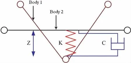
Fig.1 Penalty-based coupling
The wheel-rail interaction and bridge-ship impact both are established by penalty-based contact-impact algorithm.In this algorithm,automatic searching for interactions between two bodies is carried out to set up the coupling points on contact interface.Between two coupling points,a spring system is added to calculate the impact or contact force,and the force is proportional to the penetration and the contact rigidity.In order to restrain numerical oscillation,a viscous damper system is added to damp out the high frequency.The penalty-based system is shown in Fig.1.The normal couple force can be calculated by the Eq.(14):

where Fcdenotes normal contact force acting on body 1 face and Fsdenotes normal contact force acting on body 2;k is the stiffness of spring;Cintis the damping coefficient;Z is the penetration vector which is updated incrementally in Eq.(15):

The main difficulty in coupling comes from the evaluation of the stiffness coefficient k.Zhong[13]introduced an evaluation method for k in explicit contact algorithm,

where Kiis bulk modulus of the element;Aiis the element area;Viis the element volume;f is scale factor.
Frictional force between wheel and rail is calculated by Eq.(16):

where F*and Fnare frictional force at time n+1 and n respectively;k is stiffness,Δe is the displacement of the contact point.

4 Model description
In the past,as the limitation of computers,the analysis models of cable-stayed bridge generally were space bars model.This approach is far from perfect.With the computer techniques progress,the more complicated and refined FE models consisting of shell element,brick element and beam element can be constructed and calculated.The numerical results,especially dynamic responses,are more rational.But the reliability and accuracy of numerical results depend on the element properties,constitutive relationship of material and other crucial parameters for the analysis.
In this work,the elements of models are carefully meshed.The ratio of element length and width is not more than 5.Most elements are brick elements,and the angles in these elements are controlled between 45°~135°.The angles in tri-elements are between 20°~120°.The following sections give a brief introduction about several key components models in the system.
4.1 Bridge
Overall The Bridge is a 436 m single-tower cable-stayed bridge with double-cable planes.The main span is 251.4 m,and the bridge deck width is 18 m.Two-lane light rail lies on it.Fig.2 shows the bridge layout.

Fig.2 Bridge layouts
Main truss The cross section of main truss is rectangular.The main truss elements are shell elements.The cross section of chords and braces in main truss is box section.Both the chord and brace are consist of wing plate,stiffening rib,separation plate and bottom plate.The brace can be divided into straight brace and diagonal brace.The FE models are shown in Fig.3.
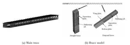
Fig.3 Main truss finite element model
Tower The tower is the key structure in cable-stayed bridge and mainly consists of column,up and down cross beam.There are holes for anchoring cables in the tower.The cables are rigidly connected with the tower through the holes.The FE model of the tower and cabletower connection are shown in Fig.4.
Cables The cable is another key component in cable-stayed bridge.It is the immediately component to burden the bridge and moving loads.The bridge dynamic response and configuration greatly depend on the tower and cable models.
The cable FE model commonly adopts three methods:equivalent elastic modulus method,segmented beam element and curved cable element.The equivalent elastic modulus method is suitable for small deformation.For the long cable,this method may produce big error.So it is not very well for modeling the long cables.The curved cable element has not been widely used yet.The segmented beam element combines the multi-beam elements to a complete cable through hinge joint.With the number of segmented beam elements increasing,the calculation accuracy for cables can be improved.So the cable model adopts segmented beam element.
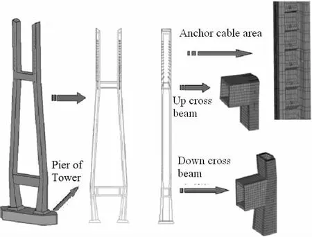
Fig.4 Finite element model of the tower
In this bridge,there are 14 pairs of cables on main span(M1~M14 in Fig.2)and side span(F1~F14 in Fig.2)respectively.The total number is 28 pairs.After carefully comparing dozens simulation tests in a preliminary phase,it is observed that each cable consisting of 30~50 elements according to the length is suitable for modeling the non-linearity of cables.The elastic modulus of cable is 195 GPa.Possion’s ratio is 0.3,and density is 7 850 kg/m3.
Deck and track Bridge deck is constructed with orthotropic plate and longitudinal and transverse beams.The material is steel.There is one concrete layer between the rail support platform and the bridge steel deck.This layer is connected with the deck by welded stud connectors.In this research,the brick elements of bridge deck,rail platform and concrete layer coincide with each other.The track includes crosstie and rail.Both of them are modeled with brick elements.Fig.5 shows these models.
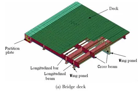
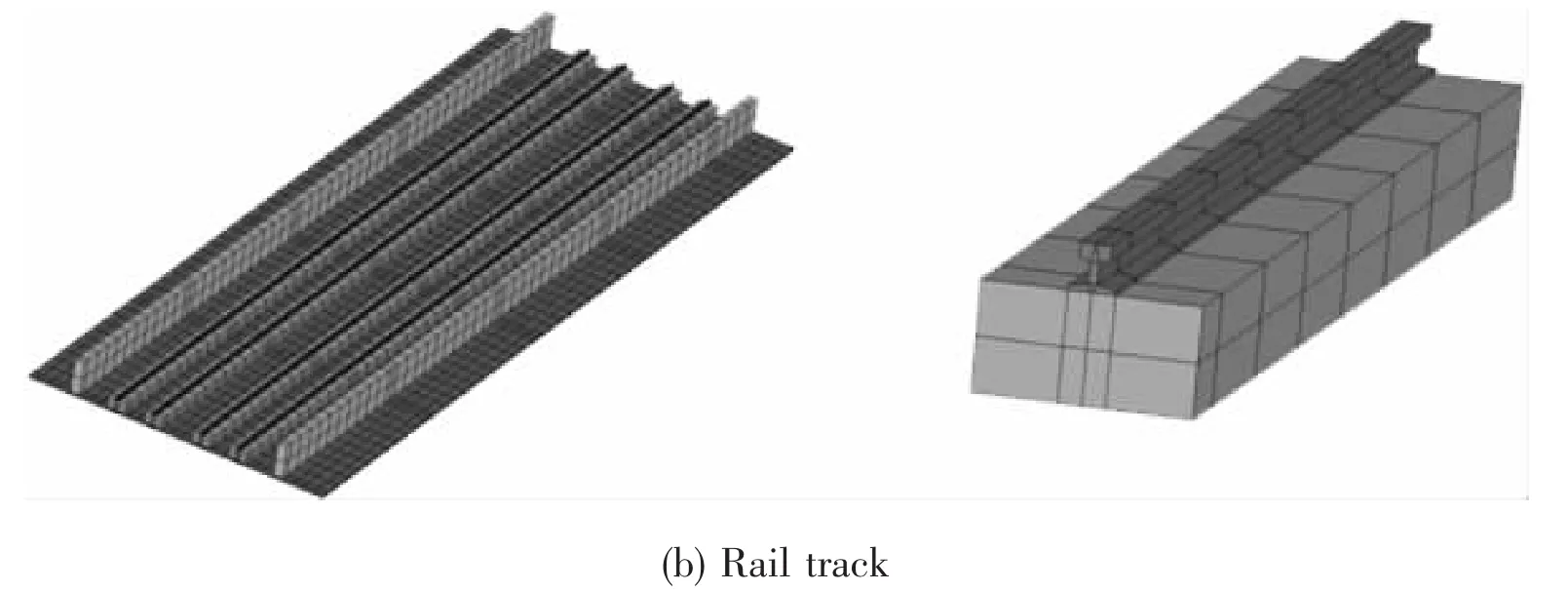
Fig.5 Bridge deck and rail track models
Pile and soil The support pile is widely used in long span bridge.Most researches regard the pile as the support platform,or fix the pile in the ground,and then the pile-soil interaction is ignored.But the base of the bridge studied in this work is soft soil layer,during the ship impact the pile-soil interaction is hardly ignored.The interaction is realized by overlapping the element nodes of piles and soil.
The pile length is 50 m,the depth of soil layers is 60 m,and i.e.the soil bottom is 10 m below the pile feet.The soil base is 20 m wider than the bridge pier.The soil layers are divided into 5~8 layers according to field survey data.The soil material parameters are also ascertained by the field survey.
The piles of main tower are steel tubes.The outer diameter is Ø900 mm,and tube thickness is 20 mm.The tubes are filled with concrete.The mechanical parameters of tubes are taken from experiments.The transition and auxiliary piles are concrete piles.The piles models adopt beam elements.The tower piles,transition and auxiliary piles are listed in Fig.6.

Fig.6 Tower pile and auxiliary pile models
4.2 Light rail vehicle
The vehicle models of the light metro,used in the present study,are schematically presented in Fig.7 and are formed by the following components:four rigid bodies with a mass to simulate four vehicles boxes;elastic springs and dash-pots to simulate the primary and secondary suspensions of the vehicles;rigid bodies with a mass to idealize the bodies;rigid bodies to simulate the axles and the wheels;and elastic springs and dash-pots to simulate the e-lastic connection between the rigid bodies.
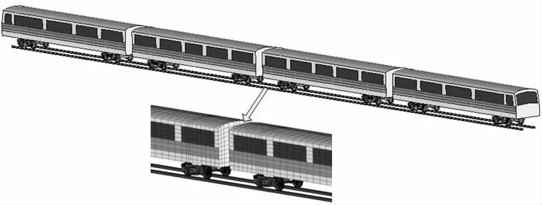
Fig.7 Finite element model of urban rail vehicle
The physical properties of the vehicle are listed in Tab.1.
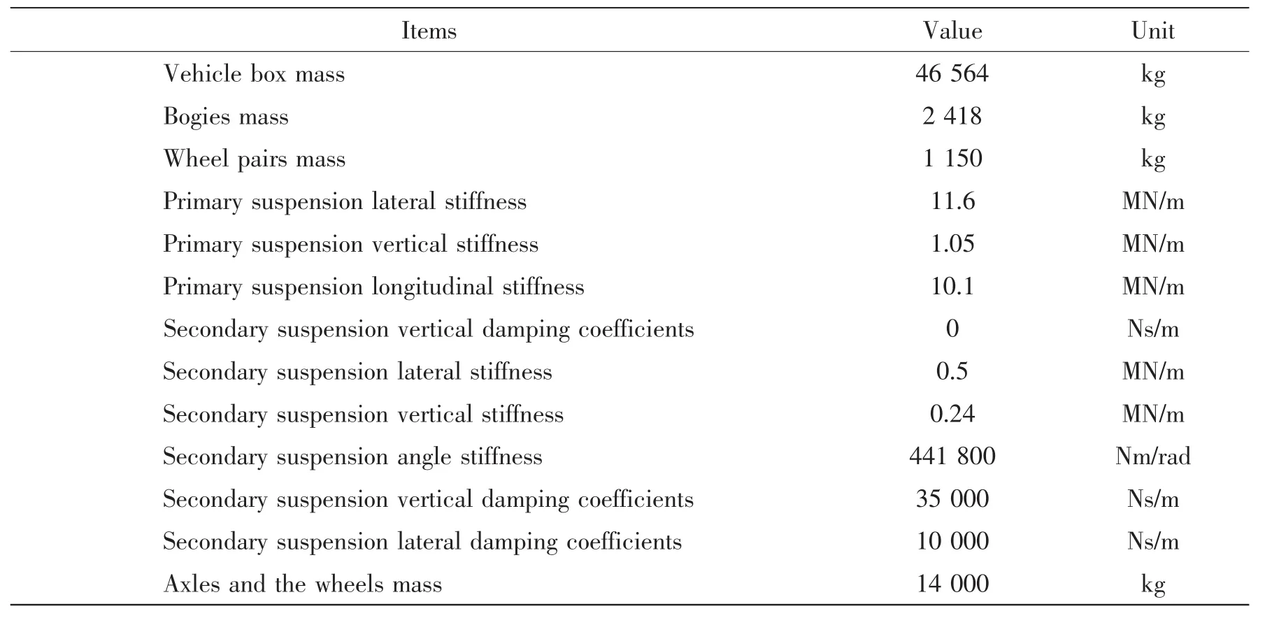
Tab.1 Performance parameters of the vehicle
The geometry of the vehicles is characterized by the following dimensions:vehicle length,width and height,distances between axles,distances between pivots,and wheel diameter.The values of the above character are indicated in Tab.2.

Tab.2 Geometric parameters of the train
Wheels and rails The refined finite element model of wheel with LM tread shape and rail with CHN60 profile is shown in Fig.8.The 3D rolling contact of wheel and rail adopts bidi-rectional contact method and symmetry penalty function algorithm.Taking wheel tread as slave surface and rail profile as master surface,it can achieve simulation of track jump and derailment for train moving on cable stayed bridge.
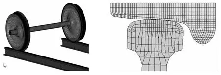
Fig.8 The finite element model of wheel and rail 3D rolling contact
4.3 Ship
The simulation of ship-bridge collision demands the accurate dynamic impact force.In order to acquire the force,special attention is given to the FE model representing the geometry and structural configuration of the ship.
Based on the statistical data,more than 90%ships sailing on the Huangpu River are 100~2 000 tons.In this paper,a FE model of the ship of 1 900 tons displacement is built.The geometry dimensions and loading are listed in Tab.3.

Tab.3 Dimensions and loading condition of the ship
During the collision,large deformations occur at the bow of the ship,so a finer mesh is used here.The rear portion of the ship does not experience the same level of deformation,and therefore the coarser mesh suffices in this region.Fig.9 shows the ship FE model.
The bow model consists of shell and inner structure.The inner structure is a frame construction and includes horizontal flat floor and deck,longitudinal keel and lateral ribs,and so on.As can be seen from the figure,the mesh of the bow is far finer than other rear portion of the ship.The mesh dimensions are about 50 mm.The ship is made of a lot of steel plates and stiffened ribs.Then,the majority of elements are shell elements in the model.The total number of nodes is 19 175,the number of elements is 20 271(the elements of the bow are 15 341).

Fig.9 Finite element models of the ship and the bow
Because the components of the bow structure may experience plastic deformation in the impact,the bow model adopts the linear hardening elastic-plastic material.The material constitutive relation is described by the Cowper-Symonds equation:
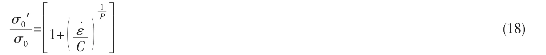
in the equation,σ0′is the dynamic yield stress,is the plastic strain rate,C and P are the parameters of,the values are 40.4 and 5,respectively.
Water The moving ship can take a large amount of water around it to move together.The water also has effect on the impact.In this research,this effect is realized with additional mass on the ship.The amount of the water depends on the ship form,velocity and impact progress.This amount can be calculated with empirical equation.In this paper,the additional mass is 0.04 of the ship mass.
5 Calculation
Using the above models,the mechanical behavior of the bridges under ship impact has been calculated with a finite element program(LS-DYNA).
The RCB(Recursive Coordinate Bisection)algorithm is the default decomposition method of the LS-DYNA.During domain decomposition,it divides the model based on equivalent number of elements and neglects the load and coupling balance.In the bridge-train-ship system,there exists much time-consuming nonlinear computation in bridge and computation of the contact among the bridge,soil,train and ship.These two kinds of computation have great effect on the computation efficiency.In order to save the calculation time,the decomposition algorithm IRCB(improved RCB)based on RCB is adopted in this paper[15].It can balance the contact computation and non-linear computation as much as possible.
The calculation of dynamic impact runs on DAWNING-4000A supercomputer with 16 AMD OPTERON 850 processors.The numerical tests take about 16~40 hours according to the different simulation tests.
6 Results and discussions
The bridge-train-ship coupling system is a complex nonlinear system.In order to obtain credible computational results,we carry out the simulation with four steps.Firstly,initial bridge state with gravity and boundary conditions is achieved and in good agreement with the design.It provides the base for the other steps.All the following models are initialized with the bridge completion state.Secondly,bridge-train coupling is simulated and its results are compared with the classical plane bars model’s results.Thirdly,the collision between bridge and ship is simulated and analyzed.Finally,based on all of the above steps,the numerical simulation for bridge-train-ship coupling is conducted.The simulation gives some meaningful results.
6.1 Initial bridge state
The initial equilibrium of the cable-stayed bridge under the dead load and cable force is known as bridge-completion state.It is a prerequisite for advanced studies.The bridge completion state is determined by reiterative calculation and finite element method.
The completion state includes two aspects:initial cable tension and bridge configuration.Fig.10(a)shows the comparison of cable tension between the design and simulation.They are basically same and the differences are less than 1%.Because the length of the chord along the bridge can reflect the bridge configuration,Fig.10(b)compares the axis lengths of each chord in the design and simulation.
6.2 Bridge-train coupling
The dynamic analysis of bridges under moving loads has been the subject of numerous researches over the years[16-18].Based on the above works,especially Leslaw’s examples,the paper carried out the simulation of bridge-train interaction by using the FE model described in Section 4.
Because the bridge is still under construction when study is being carried out,it is hardly to compare the simulation with the field experiment.So the results of a validated plane bars model used in design phase are presented for evaluating the FE models and simulation results.
The results of the plane bars model come from Ref.[18].All geometry and physic parameters of the bridge and train are the same with the FE model illustrated and listed in Section 4.
In the simulation,the train travels from the left end to the right end(Fig.2)at 80 km/h.Fig.11 shows the deflection time history curves of three locations.The locations are labeled in Fig.2:the tower top(location A),the mid-point of main span(location B)and the mid-point of side span(location C).Tab.4 lists max-deflection of both models.

Tab.4 Simulation results comparison


Fig.11 Displacement curves
Based on the above figure and table,the bridge-train coupling results of FE model and plane bars model show well consistency.As mentioned in Section 1,the bars models of bridge have been widely used in engineering area and its calculation results have been accepted in a large extent.So the above comparisons of simulation results prove that the FE models and bridge-train coupling described in the paper are credible.
Bars model and 3D FE model have their own characteristics and are complement each other.In early design phase,for rapidly comparing different schemes,bars model is a better choice.The 3D FE model is more suitable for comprehensive analyzing bridge structure,improving and optimizing design schemes.
6.3 Bridge-ship collision
In this research,the ship velocity is 4.12 m/s and the impact location is the pier of the bridge tower.It supposes there is no train traveling on the bridge during the collision.Considering different impact angle,the collision is sorted to front impact and side impact(the angle is 45°),as Fig.12 shows.

Fig.12 Finite element models of the collision
The collision is a strong nonlinear process.In the process,the impact energy transforms to the deformation of ship and pier.The plastic deformation in the bow structure may cause bulking collapse.In both front and side impact,the collapse commonly occurs on the contact area between the pier and the ship.
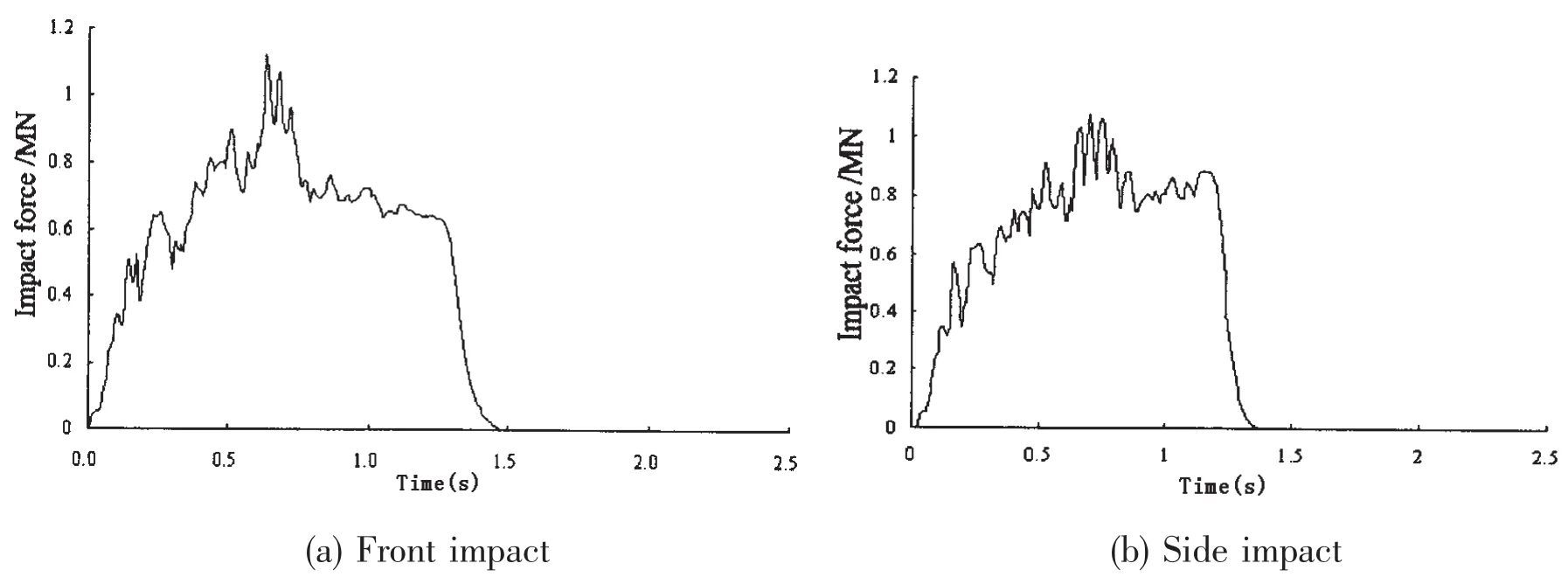
Fig.13 Impact force
Fig.13 are the impact force curves.The curves exhibit strong non-linear oscillation.It shows that the bow structure experienced many loading and unloading cycles.These cycles mean the structure and components of the bow are destroyed or failed.The impact force increases dramatically,and then reaches maximum.After that,the ship is bounced,the force decreases to zero and the interaction between the ship and thepier terminates.The collision process is about 1.4 s.As Tab.5 shows,the impact force in front impact is larger than in side impact.
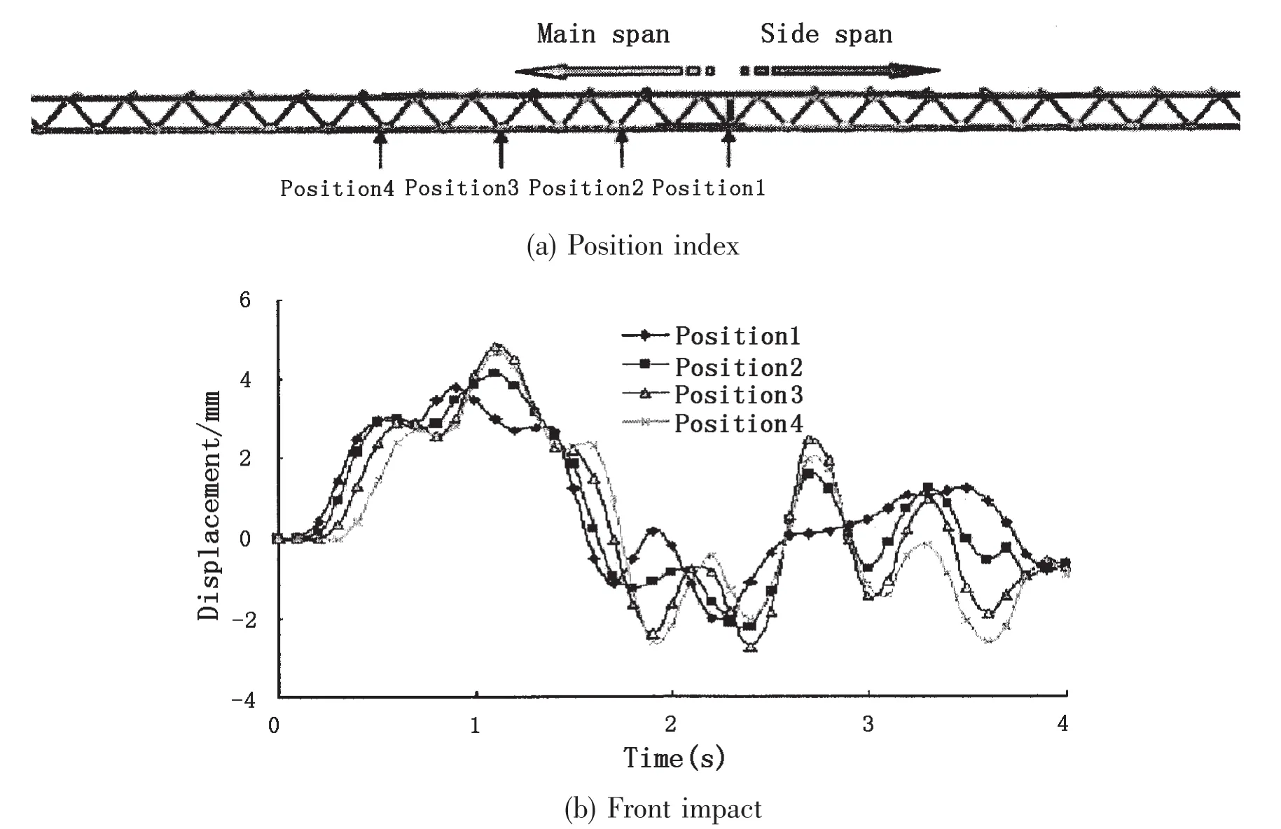

Fig.14 Horizontal displacements curves of the deck in the impact
The bridge tower vibrates because of the collision.The impact force on the pier and the vibration can be transmitted to other components of the bridge including the deck through the cables and cross beams.The dynamic response of the deck may produce large stress in bridge and affect traveling safety of the train.The displacements of several positions on the deck have been shown in Fig.14.
It can be seen from the figure that the moment when max-displacement happens in side collision is later than it happens in front collision.The max-displacements of different locations in front impact are all larger than those in side impact.Tab.5 shows these differences more clearly.It means that at the same impact velocity the front impact more easily leads the train to derailment.
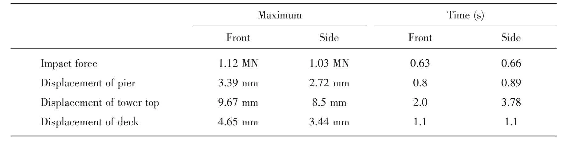
Tab.5 Results of ship impact
Another observation made from the above plots is that the impact of collision on the bridge mainly ranges from the middle of main span to the tower.The largest dynamic response of the bridge deck happens on position 1 where the tower locates.The dynamic response continues for 4 seconds.
6.4 Bridge-Train-Ship
Based on the above works,authors carried out dynamic numerical simulation for bridgetrain-ship system.According to the analysis in Section 6.3,the bridge-ship collision is the most dangerous for train safety when the light metro is traveling on the main span,especially the first carriage of the light metro is arriving at the tower.So the simulation test is:the train travels from the left end to the right end at 80 km/h.The ship impacts the bridge pier at the moment the first vehicle of light metro is running at the position1(Fig.13).The ship impact velocity is 4.12 m/s.Both the front and side collisions are conduced.
The deck dynamic response caused by the impact affects the train safety through wheelrail interaction.Fig.15 shows wheel and rail lateral interaction force curves.Before the impact moment(about 11 s)the train is normally running,when the collision happens,the lateral interaction force increases obviously.
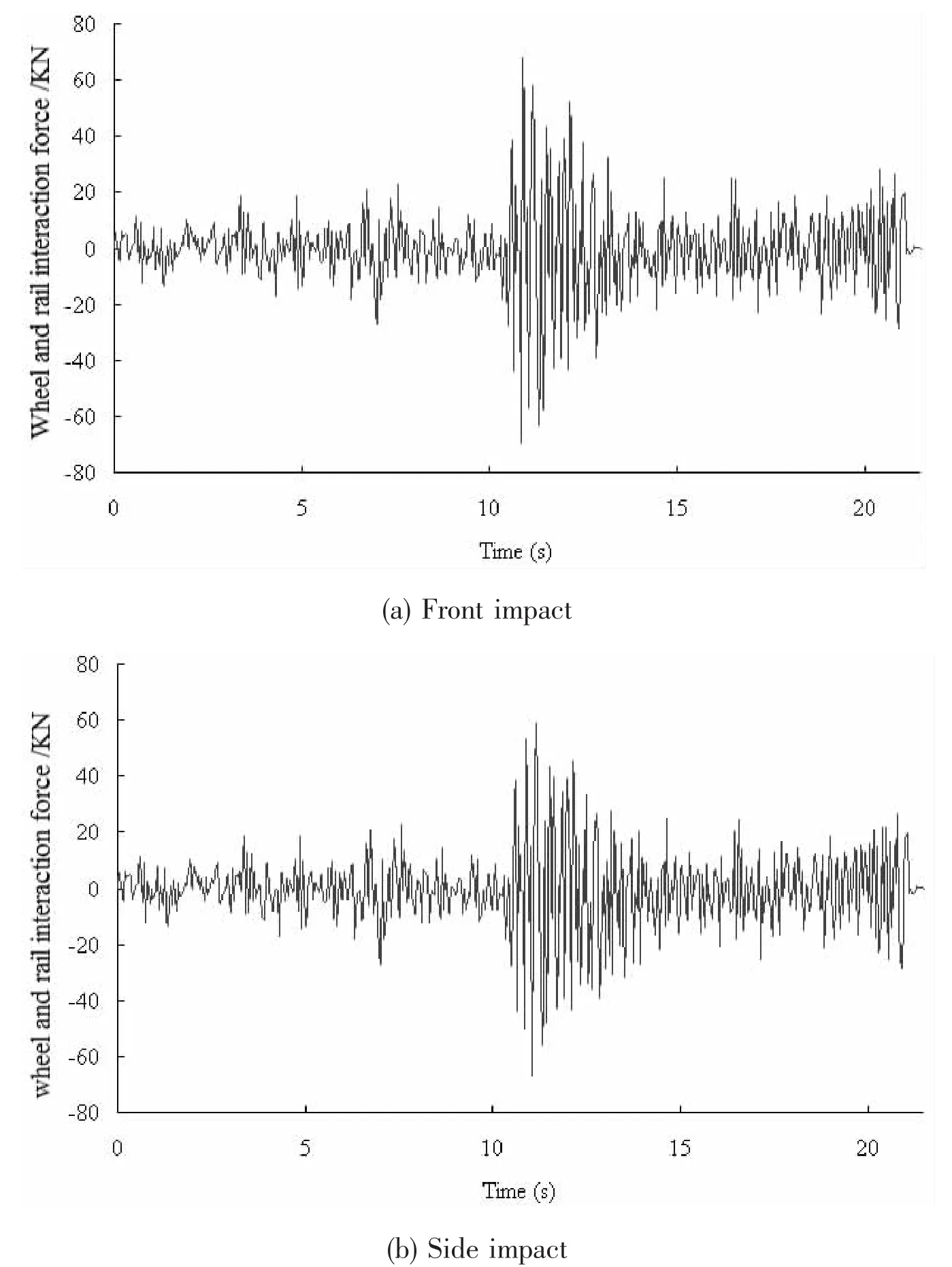
Fig.15 Wheel and rail lateral interaction force
Fig.16 illustrates the lateral displacements time history curves of the third vehicle box.The max-displacement is 30 mm.
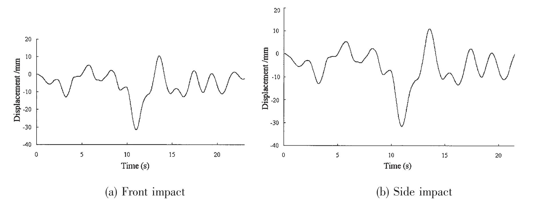
Fig.16 Displacements of the third vehicle box
Tab.6 gives the wheel load reduction rate and derailment coefficient in both collisions.The limitation value of the wheel load reduction rate is 0.6.So both the collisions cannot lead to the derailment.However,the safe factor is low.
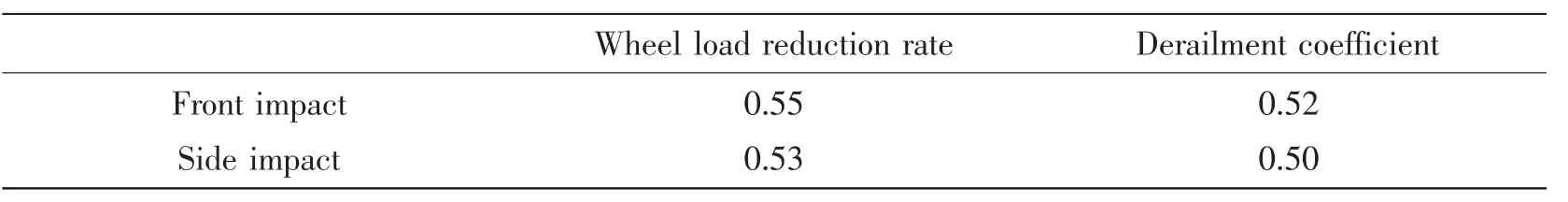
Tab.6 Dynamic responses of the vehicle
The bridge-ship collision can greatly raise the risk for derailment.And the risk increases with the increase of tonnage and impact velocity of the vessels.For more serious collision,the existing methods and systems are still far from protecting the safety of the moving train.It is necessary to install more effective anti-collision systems,shock absorbers and fenders on the bridge.
7 Summary and conclusions
With urban mass transit developing and the traffic flow increasing,the study on the effects of the bridge-ship collision on the train safety becomes more important.The primary objectives of this study are to predict,using nonlinear finite element analysis,the dynamic response of bridge and to analyze the risk of the moving train due to the ship impact.
In order to accomplish these objectives,the 3D finite element models of a constructing cable-stayed bridge,light metros and ship have been built up.The bridge model includes truss,tower,cables,piles,soil layers,deck and tracks,etc.The light metros model consists of four vehicles boxes,the primary and secondary suspensions,the bogies,the axles and the wheels and the connection between vehicles.For well simulating the bridge-ship collision,a ship model with detailed bow structure is built and the water around the ship is taken into account as additional mass.
The approaches used in the paper can be well applied on dynamic analysis of the cablestayed bridge-train-ship interaction,such as contact-impact algorithm,U.L and C.R.formulation,and so on.The paper presents a four-step approach to conduct numerical simulations for analysis of the dynamic response of the system using the LSDYNA finite element code.
Validation of the approaches and FE models are carried out by comparing the results with the empirical models used in design specifications.Some preliminary results of the approaches and models are presented and discussed to demonstrate their capability and potential in simulating bridge-train-ship dynamic response.Some other conclusions can be made as follows:
(1)Both the impact force and bridge deformation in front impact are larger than those in side impact.In long span cable-stayed bridge,the effect of collision on the tower pier mainly ranges from the middle of main span to the tower.The max-displacement of the deck occurs at the locations near the tower.It means that the collision is the most dangerous for train safety when the train is traveling on the main span,especially the first carriage of the train is arriving at the tower.
(2)Although most ship collision accidents cannot lead to the bridge collapses by using the present anti-collision measures.But considering the safety the moving vehicles on the bridge,special and additional anti-collision systems and methods should be adopted.
[1]Woisin G.The collision tests of the GKSS[J].Jahrbuch Schiffbautech Gesellsch,1976,70:465-487.
[2]Meir-Dornberg KE.Ship collisions,safety zones,and loading assumptions for structures in inland waterways[J].VDIBerichte,1983,496:1-9.
[3]Consolazio G R,Cowan D R.Nonlinear analysis of barge crush behavior and its relationship to impact resistant bridge design[J].Computer and Structure,2003,81(8):547-557.
[4]Liu Jiancheng,Gu Yongning.Simulation of the whole process of ship-bridge collision[J].China Ocean Engineering,2002,16(3):369-382.
[5]Whitney M W,Harik I E,Griffin J J,Allen D L.Barge collision design of highway bridges[J].ASCE J Bridge Eng,1996,1(2):47-58.
[6]Proske D,Curbach M.Risk to historical bridges due to ship impact on German inland waterways[J].Reliability Engineering and System Safety,2005,90(3):261-270.
[7]Wuttrich R,Wekezer J,Yazdani N,et al.Performance evaluation of existing bridge fenders for ship impact[J].Journal of Performance of Constructed Facilities,2001,15(1):17-23.
[8]Yang Y B,Wu Y S.Dynamic stability of train moving over bridges shaken by earthquakes[J].Journal of Sound and Vibration,2002,285(1):65-94.
[9]Song Myung-kwan,Noh Hyuk-Chun,Choi Chang-Koon.A new three-dimensional finite element analysis model of highspeed train-bridge interaction[J].Engineering Structures,2003,25:1611-1626.
[10]Hillmann J,Koeing C,Wang X.10 years of crash simulation at Volkswagen[C].Proceeding of 2nd International LS-DYNA Conference,1994.
[11]Zhang Xiaoyun,Jin Xianlong,Qi Wenguo.Crashworthiness simulation and structure optimization design of auto-body based on finite element method[J].Journal of Systems Engineering and Electronics,2004,15(4):112-116.
[12]Chw eizerhof K,N ilsson L,Hallquist J O.Crashworthiness analysis in the automotive industry[J].International Journal of Computer Applications in Technology,1992,5(4):134-156.
[13]Zhong Z H.Finite element procedures for contact-impact problems[M].Oxford University Press,Oxford,1993.
[14]Li Zheng,Jin Xianlong,Chen Xiangdong.Parallel numerical simulation with domain decomposition for the fluid-filled drum crash,Institution of Mechanical Engineers,Part C[J].Journal of Mechanical Engineering Science,2008,222(3):319-328.
[15]Diana G,Cheli F.Dynamic interaction of railway systems with large bridges[J].Vehicle System Dynamic,1989,18(1-3):71-106.
[16]Khalifa M A.Parametric study of cable-stayed bridge response due to traffic-induced vibration[J].Computer and Structure,1993,47(2):321-339.
[17]Au F T K,Wang J J,Cheng Y K.Impact study of cable-stayed bridge under railway traffic using various models[J].Journal of Sound and Vibration,2001,240(3):447-465.
[18]The Design and Calculation Report of XXX Bridge[R].Shanghai:Shanghai Urban Construction Design and Research Institute,2007.

- 船舶力学的其它文章
- Experimental Study of the Motion Responses of a Large Mooring(LNG)Ship in the Waves with Grand Period
- CLSVOF Method for Violent Sloshing with Impact Load in Tanks under Shallow Water Depth
- A New Method for Predicting the Steady Performance of Ducted Propeller with Stators
- Experimental Research on Hydrodynamic Characteristics of Propeller in Waves
- Research on Method for Optimization Design of Riblets Angle based on CFD Techniques
- Online Prediction of Ship Rolling based on Varying Parameters LSSVM