
CLSVOF Method for Violent Sloshing with Impact Load in Tanks under Shallow Water Depth
2012-12-13 02:56LIUYongtaoMANingZHURenqingGUXiechong
船舶力学 2012年9期
LIU Yong-tao,MA Ning,ZHU Ren-qing,GU Xie-chong
(1.School of Naval Architecture,Ocean and Civil Engineering,Shanghai Jiao Tong University,Shanghai 200240,China;2.School of Naval Architecture and Ocean Engineering,Jiangsu University of Science and Technology,Zhenjiang 212003,China)
1 Introduction
Nowadays violent sloshing problem with impact load on tank structure is a critical issue for the design of large liquid ships such as LNG ships.And effective prediction of the impact load on local tank walls aroused by sloshing is a challenging work.Although,several CFD methods have been adopted for numerical simulation in this field,such as VOF[1],level-set[2],CIP[3],SPH[4],MPS[5]et al,and extensive studies have been carried out.But due to the strong nonlinearity of the sloshing phenomenon,some particularities have not been revealed satisfactorily.And the sloshing problem in tank with shallow water depth under resonant excitation is a typical example,in which complicated sloshing phenomenon such as traveling wave and breaking wave produces and poses impulsive impact on the tank wall.
Among all the CFD approaches,the volume-of-fluid(VOF)method[6-7]is popularly used for the simulation of interface flow.By adopting a volume fraction in a cell to represent the interface,VOF method is advantageous for mass conservation.Among present reconstruction schemes,piecewise linear interface calculation(PLIC)[7]is a modern method and gain more accuracy on interface reconstruction.However,the geometric advection scheme is required for the interface cells,and this constraints the accuracy of the method.
The level set method[8-9]represents the interface implicitly by an iso-surface of a scalar level-set function.So this method is advantageous for automatic handling of topology changes,and accurate computation of the interface normal and curvature.Besides,the interface advection process will distort the level set function,so a re-initialization process is needed.However,because of poor mass conservation property,the level set methods have severe drawbacks on mass conservation issues.
In order to achieve both good mass conservation and smooth interface configuration,the hybrid approaches are good choices.Sussman et al[10]firstly presented a coupled level-set and VOF approach(CLSVOF)to simulate incompressible two-phase flows.Then this method has been employed and developed to simulate free surface flows,such as simulation of two-phase flow adopting CLSVOF on 3D tetrahedral grids by Lv et al[11],simulation of the plunging breaking waves by Wang et al[12],simulation of vapor bubbles dynamics by Sussman et al[13],simulation of the primary break-up of a liquid jet by Menard et al[14].
In this study,a CLSVOF method is employed for the numerical simulation of violent sloshing problems with impact load.The interface is reconstructed by a PLIC VOF construction scheme and is propagated using a Lagrangian splitting method.The level set function is re-distanced based on the reconstructed interface.Two cases about violent sloshing in tanks under resonant period under shallow water depth are simulated and compared with the available experimental results.
2 Governing equations
Considering a viscous and incompressible flow assumption,the governing equations for liquid sloshing in tanks are as follows:

where D/Dt is derivative in fixed coordinate,V is velocity vectorof fluid,Fbis body force,p is fluid pressure,ρ is density of the fluid in tanks and μ is dynamic viscosity.
Continuity equation(1)and momentum transport equation(2)are discretized by finite different methods with cartesian grids.A projection method is adopted to solve the velocity and the pressure with a 2nd-order central scheme for spatial derivatives.
3 Numerical scheme
3.1 VOF method
For volume-of-fluid(VOF)method,a volume fraction scalar F is defined in each cell which is within 0.0 to 1.0:

To be precise in advection computation,nowadays PLIC VOF[15]gains widely popularity among VOF methods.For this scheme,the interface is approximated as a plane(or line for 2-D)in a cell.In 2-D case,the equation for a constructed line in a cell with unit normal vector n is:

where,α is the shortest distance form the origin to the line.
For traditional PLIC VOF method,plane normal vector(nx,ny)can be firstly evaluated according to the following equation:

For the interface,it can be tracked according to the following advection equation:

To solve the above equation,a robust Lagrangian method[15]is employed to simulate the interface motion.
3.2 Level-Set method
As an effective method to track the interface between fluids,nowadays the level set(LS)method has been employed to model two phase flows problems.
For LS method,the moving interface is the zero contour of the level set function,namely

And the scalar function φ(x,t)is generally defined as the signed distance from point x to interface Γ(0).Therefore,level set function φ(x,t)observes the following function:
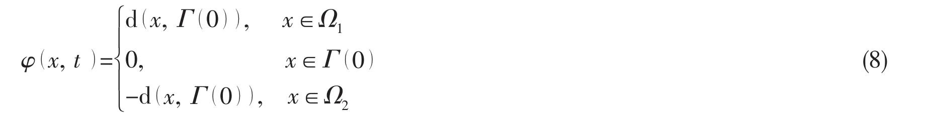
For this function,it is zero at the interface,positive in one side of the interface and negative in the other side.
The main drawback of LS method is that,the LS function φ(x,t)fails to be a signed distance function to the interface,after several time step integration.So the LS function φ(x,t)needs to be reinitialized at every time step.To achieve this goal,we can solve Eq.(19)for the steady-state solution:

To be simple,the signed distance function can be smoothed as follows:

The curvature k which is related to normal vector n can be calculated from the level set function by the following equation:

where normal vector n has the following form:

When the interface evolves with the velocity field,the LS function should satisfy the following equation:

where V is fluid velocity at the interface.
3.3 CLSVOF method
In the present study,the interface is reconstructed by PLIC VOF scheme with a plane approximation in a cell,while the normal vector at the interface is obtained from the LS function.On the newly reconstructed interface,the LS functions are re-distanced to satisfy mass conservation.The flow chart for the CLSVOF method is shown in Fig.6.
3.3.1 Fluid domain initialization
Firstly the initial distribution of fluid variables should be determined,such as the veloci-the pressure p0,the volume fraction F0and the LS function φ0.
人参皂苷Rc还具有增强精子活力[43]、抑制固定应激引起的血浆皮质酮水平的增加[44]、剂量依赖性的镇痛[45]、预防骨质疏松[46]、抑制活化的肾成纤维细胞增殖、防治肾纤维化[47]、抑制非人参病原菌和人参锈腐病菌菌丝生长[48]、诱导CYP1A1 mRNA与蛋白表达[49]等作用,且其没有胚胎毒性[50]。
3.3.2 Solving Navier-Stokes equation
Projection method is applied to calculate the(u,v)and p,then go to step 3.3.3.
3.3.3 CLSVOF interface advection
The CLSVOF interface propagation procedure includes the following steps:
(1)The governing equations evolution step:In CLSVOF method,the governing equations for interface propagation are Eq.(5)and Eq.(8)for the VOF and LS functions respectively.The evolution of these two equations can be solved by the split advection scheme[10].
(2)The interface reconstruction step:The interface is reconstructed by PLIC VOF scheme with volume fraction determined by Eq.(5)and normal vector obtained from the LS function.And the LS function is modified to satisfy mass conservation with given volume fraction.The detailed procedure is shown in Ref.[14].
(3)The volume fraction truncation step:The volume fraction is truncated with the LS function to remove spurious volumes as follows:
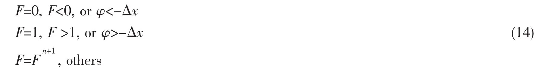
In the first sub-step,the sign of the LS function is given by sign(F-0.5).When F>0.5,the cell center will be in the liquid and the LS function has the positive sign,and vice versa.
In the second sub-step,the magnitude of the LS function is assigned to be the shortest distance from the cell centers to the reconstructed interface.To obtain the shortest distance,the key point is to find the closest point on the cell boundary or the interface segment[10-16].As shown in Fig.1,the interface reconstructed in the cell A is line segment GH.The shortest distance from the centers of cells B,C,and D to interface cell A are line segments BE,CH,and DI respectively according to the geometric discipline.
After the above sub-steps,then go back to step 3.3.2.
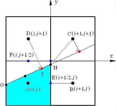
Fig.1 2-D schematic view for the LS function re-distance scheme
4 Numerical results
4.1 Violent sloshing in tanks with harmonic roll motion
Tank dimension(experiment by Delorme[17]):Length L=0.90 m,height H=0.58 m,breadth B=0.10 m,filling height h=0.093 m.The tank is oscillated with harmonic roll motion described asRoll amplitude θAis 4.0°,and the resonant period T0under the water depth of 0.093 m is 1.92 s.Three different excitation periodsare considered,which arerespectively.

Fig.2 Interface profiles of experimental snapshot(by Delorme[17])(left)and CLSVOF simulation(right)for case A
For problem of shallow water sloshing in tanks,traveling wave and breaking waves are observed under external resonant excitations of roll motion.Therefore,high pressure is found during the impact event when a breaking wave approaches the wall.Effective simulation of such phenomenon is a challenging work,and also an important aspect for determination of impact load.As shown in Fig.2,the traveling wave and its breaking event are well reproduced by CLSVOF method corresponding to the experimental events for case A which is near resonance excitation.
The pressure gauge is placed at the initial water depth on the left tank wall.In Fig.3 and Fig.4,the variables are defined to be dimensionless,so we have the dimensionless pressure p1the dimensionless angleand the dimensionless time t1=t/T.

Fig.3 Comparison of pressure time history between the experiment(by Delorme[17])and simulation by CLSVOF for cases A,B,and C
The pressure time histories from the pressure gauge are compared between the numerical results and the experiment ones[17]from cases A,B and C in Fig.3.Within fifteen excitation periods,it shows that the peak pressures by CLSVOF are larger than their experimental peak values for cases A and B.While for case C,experimental peak value is larger than the simulation value.And the peak pressure by CLSVOF varies slightly from 3.0 to 5.0,while the ex-perimental peak pressure has a large variation from 2.0 to 8.0,concluded from cases A,B and C.But the pressure curves by CLSVOF conform well with the corresponding experimental ones in general.Also,the pressure evolutions during the first impact event are specially zoomed in the Fig.4.Compared with the experimental results,it can be seen that simulated first impact pressure is a bit larger than the experimental ones.But,compared with the results(red line in Fig.4)form Ref.[11],good accordance is observed both in peak value of the pressure and duration time of the impact.
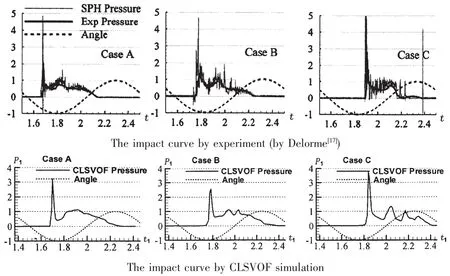
Fig.4 Comparison of the impact curve between the experiments(by Delorme[17])(upper)and simulations by CLSVOF(lower)during the first impact event
4.2 Violent sloshing in tanks with harmonic sway motion
Tank dimension(experiment by Hu[18]):Length L=0.60 m,height H=0.40 m,breadth B=0.10 m,filling height h=0.06 m.The tank is oscillated with harmonic sway motion described as η=ηA·sin(wt).Sway amplitude ηAis 0.05 m,and period T are 1.70 s and 1.30 s which is equal to resonant period of 0.06 m filling height.The pressure gauge is located at the right tank wall which is 5 cm height above the tank bottom.
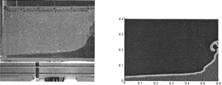
Fig.5 Interface profile of experiment by Hu[20](left)and CLSVOF simulation(right)for the period of 1.30 s
In this case,violent sloshing phenomenon such as breaking,hitting the tank ceiling et al occurs because of resonant sway oscillation as showed in Fig.5.On the event of hitting the tank ceiling,the local interface is separated to form many fragments.For simulation of this event,CLSVOF approach is prone to eliminate these fragments due to the mechanism of LS function.Therefore the simulated interfaces are slightly differ-ent from experiment snapshots at top position on the right wall as shown in Fig.5.For the curves of pressure time history,both the simulation results and the experimental results share the same tendency as can be seen in Fig.6.

Fig.6 Comparison of pressure curves between the experiment(by Hu[17])and simulation
5 Conclusions
This paper employed a CLSVOF method to simulate violent sloshing problems with impact load in tanks.The interface is reconstructed by a PLIC VOF scheme.On the reconstructed interface,the level set function is re-distanced.This method gains the advantages of good mass conservation as well as smooth surface configuration.Taking advantage of this CLSVOF method,for violent sloshing in tank under resonant period,the shallow water sloshing flows in tanks are simulated and compared with the available experimental results,and good agreements are obtained.
[1]Kim Y.Numerical simulation of sloshing flows with impact load[J].Applied Ocean Research,2001,23:53-62.
[2]Zhu R,Fang Z,Zhang Z,Chen Z.Level-set method for predicting impact pressure induced by violent sloshing in a tank[J].Journal of Ship Mechanics,2008,12(3):344-351.
[3]Hu C H,Yang K K,Kim Y H.3-D numerical simulations of violent sloshing by CIP-based method[C]//Proceedings of the 9th ICHD.Shanghai,China,2010.
[4]Rudman M,Prakash M,Cleary P W.SPH modeling of liquid sloshing in a LNG tank[C]//Proceedings of the 9th ISOPE.Osaka,Japan,2009.
[5]Hu C,Sueyoshi M,Miyake R,Zhu T,Dobashi H.A validation study of applying the CIP method and the MPS method to 2-D tank sloshing[C]//Proceedings of the 9th ISOPE.Osaka,Japan,2009.
[6]Hirt C W,Nichols B D.Volume of fluid(VOF)method for the dynamics of free surface fluid flow[J].Journal of Compute Physics,1981,39:201-225.
[7]Youngs D L.Time-dependent multi-material flow with large fluid distortion[C]//Numerical methods for fluid dynamics.Academic,New York,1982:273-285.
[8]Sethian J A.Level Set Methods and Fast Marching Methods[M].Cambridge:Cambridge University Press,1996.
[9]Osher S,Fedkiw R.Level set methods and dynamic implicit surfaces[C].Applied Mathematical Sciences,Springer Press,New York,2003,153.
[10]Mark Sussman,Elbridge Gerry Puckett.A coupled level set and volume-of-fluid method for computing 3d and axisymmetric incompressible two-phase flows[J].Journal of Computational Physics,2000,162:301-337.
[11]Lv Xin,Zou Qingping,Zhao Yong,Dominic Reeve.A novel coupled level set and volume of fluid method for sharp interface capturing on 3D tetrahedral grids[J].Journal of Computational Physics,2010,229:2573-2604.
[12]Wang Zhaoyuan,Yang Jianming,Bonguk Koo,Frederick Stern.A coupled level set and volume-of-fluid method for sharp interface simulation of plunging breaking waves[J].International Journal of Multiphase Flow,2009,35:227-246.
[13]Sussman M.A second order coupled level set and volume-of-fluid method for computing growth and collapse of vapor bubbles[J].Journal of Computational Physics,2003,187:110-136.
[14]Menard T,Tanguy S,Berlemont A.Coupling level set/VOF/ghost fluid methods:Validation and application to 3D simulation of the primary break-up of a liquid jet[J].International Journal of Multiphase Flow,2007,33:510-524.
[15]Denis Gueyffier,Li Jie,Ali Nadim,Ruben Scardovelli,Stephane Zaleski.Volume-of-Fluid interface tracking with smoothed surface stress methods for three-dimensional flows[J].Journal of Computational Physics,1999,152:423-456.
[16]Son G,Hur N.A coupled level set and volume-of-fluid method for the buoyancy-driven motion of fluid particles[J].Numer.Heat Transfer B,2002,42:523-542.
[17]Delorme L,Colagrossi A.A set of canonical problems in sloshing,Part I:Pressure fielding forced roll-comparison between experimental results and SPH[J].Ocean Engineering,2009,36:168-178.
[18]Zdravko R,Kishev,Hu Changhong,Kashiwagi Masashi.Numerical simulation of violent sloshing by a CIP-based method[J].Journal of Marine Science Technology,2006,11:111-122.
猜你喜欢
昆明医科大学学报(2021年8期)2021-08-13
云南医药(2021年3期)2021-07-21
数学年刊A辑(中文版)(2018年2期)2019-01-08
中成药(2018年9期)2018-10-09
中成药(2017年9期)2017-12-19
商情(2017年38期)2017-11-28
中成药(2017年6期)2017-06-13
中国洗涤用品工业(2017年2期)2017-04-16
中国现代医学杂志(2015年26期)2015-12-23
中国医疗美容(2015年1期)2015-07-12

- 船舶力学的其它文章
- Experimental Study of the Motion Responses of a Large Mooring(LNG)Ship in the Waves with Grand Period
- A New Method for Predicting the Steady Performance of Ducted Propeller with Stators
- Experimental Research on Hydrodynamic Characteristics of Propeller in Waves
- Research on Method for Optimization Design of Riblets Angle based on CFD Techniques
- Online Prediction of Ship Rolling based on Varying Parameters LSSVM
- In-line Dynamic Characteristic of a Circular Cylinder under Vortex-induced Vibration