
A New Method for Predicting the Steady Performance of Ducted Propeller with Stators
2012-12-13 02:56SUYuminLIUYebaoSHENHailongJULei
船舶力学 2012年9期
SU Yu-min,LIU Ye-bao,SHEN Hai-long,JU Lei
(National Key Laboratory of Science and Technology on Automatic Underwater Vehicle,Harbin Engineering University,Harbin 150001,China)
1 Introduction
Ducted propeller has become an attractive propulsion for ship and underwater vehicle due to its advantages of protecting propellers,increasing propulsive efficiency and improving propeller cavitation performance.The studies show that the use of fixed stator blades upstream or downstream of propeller can improve the flow field,reduce the rotational losses and increase the propulsive efficiency.Since the ducted propellers often require the structures to support duct,these structures can be considered as stator blades.The stator blades installed in front of the propeller in a ducted propeller can supply a pre-swirl flow for propeller and make the inflow of propeller more symmetrical.Thereby,the propulsive efficiency and noise performance are improved.The stators situated behind the propeller can make use of the rotation energy to increase the propulsive efficiency[1].
The hydrodynamic performance of the ducted propeller with stators has made great progress abroad.Hughes and Kinnas[2-3]predicted the performance of ducted propellers with pre-swirl stators.In their calculation,the lifting surface theory was used on the propeller and stators,and the panel method was applied for duct and hub.Kawakita and Hoshino[4]developed a method for the steady performance of the ducted propeller with stators behind the propeller based on surface panel method.Professor Wang and his students[5-7]adopted similar method to compute the performance of the ducted propeller with pre-swirl stators or stators behind the propeller,and the influence of the potential based and velocity based iteration among propeller,stators,duct on the performance were analyzed.
However,the stators and the duct are separately considered in the calculations above.In fact,the stators and duct are one piece,and they are stationary components.In the paper,the stators and duct are taken into account as a whole,which can be described as stator-duct system.The interaction between propeller and stator-duct system is calculated by induced velocity iteration.
2 Numerical methods
Considering a ducted propeller with stators working in the flow,the duct,stators are taken into account as a whole.A potential based panel method is applied for both propeller and stator-duct system.According to the Green’s formula[8],the potential on propeller can be written as follows:

where:Ss+Sd,Ssw+Sdw are the combined duct-stator surface and the combined wake surface,respectively;Sp,Spw are the propeller surface and its wake surface;RPQis the distance between the control point P and the boundary point Q on the surface;Δφ is the jump of potential across the wake surface;themust satisfy the kinematic boundary condition which normal velocity is zero.The value ofis the perturbation velocity normal to the boundary surface.Considering the propeller is working in the induced flow of stator-duct system and stator-duct system is working in the induced flow of propeller,theon propeller and stator-duct system can be written respectively as[9]:

where:V0is the inflow velocity along the axis of propeller;Ω is the rotation velocity of propeller;is the velocity on propeller induced by stator-duct system;is the velocity on stator-duct induced by propeller.

Fig.1 The calculation model of ducted propeller with stators
According to the surface panel method theoretics and the panel arrangement of the ducted propeller with stators showed in Fig.1.Eq.(1)and Eq.(2)can be discretized into two sets of linear algebraic equations as follows:

where:Np,Nwpare the panel number on the propeller of one blade and its wake;Nsd,Nwsand Nwdare the panel number on the stator-duct system and their wake;Δφ is the potential difference between upper side and lower side at trailing edge of propeller or stator,duct;n is the rotating velocity(rps)of propeller;rjis the radius of the No.j panel;njis the outside unit normal vector of No.j panel;δijis the Kronecker function;C,B and W are the potential influence coefficients which can be solved by Morino resolution.
For the steady case,the potential on every stator blade is equivalent.Therefore,Eq.(6)can also be written as:

where:N1sdis the panel number on one stator and corresponding duct part,N1ws,N1wdare the panel number of their wakes.The surface panel arrangement on one stator and corresponding duct part with their wakes are shown in Fig.2.The influence of the other stators and duct parts can be calculated during the influence coefficient calculation.The use of Eq.(7)can save much calculating time.

Fig.2 The surface number on one stator and corresponding duct part with their wakes

Eq.(5)and Eq.(7)can be solved by applying the non-linear equal-pressure Kutta condition to the propeller blade,stator and duct trailing edge.The Kutta condition of propeller is described as:

The Kutta condition of stator-duct system is written as:
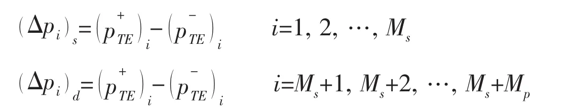
where:Mp,Msand Mdare the spanwise panel number of propeller,stator and duct;The subscript TE means the trailing edge;p+and p-are the pressure of the upper side and lower side.
The performance calculation procedure of ducted propeller with stators can be described as:First,apply Eq.(5)and Eq(8)to calculate the open water propeller performance and its induced velocity on stator-duct system;Second,add the induced velocity of propeller on statorduct to solve Eq.(7)and use Eq.(9)to calculate the stator-duct system induced velocity field;Third,add the induced velocity of stator-duct on propeller to calculate the propeller performance and its induced velocity field again.Repeat step second and third until the thrust coefficient and torque coefficient of propeller and stator-duct system are convergent.
The hydrodynamic performance of ducted propeller with stators can be described as:

where:Kt,Kqdenote the total thrust coefficient and torque coefficient of the ducted propeller with stators;Kts,Ktdare the thrust coefficient of stator and duct respectively;Tp,Tsand Tddenote the thrust of propeller,stator and duct;QPis the torque of the propeller;D is the diameter of propeller.
3 Numerical results
Numerical calculations are carried out for a ducted propeller with stators described in Ref.[2].The propeller model is Modified MIT propeller#76.The section plane of stator is NACA63-018,and the stator has 9 blades whose installing angle is 3°or 9°.The length of duct is 192.405mm.Detailed size and position of this duct propeller are shown in Ref.[2].The hydrodynamic performance calculation results of ducted propeller with stators are shown in Fig.3,Fig.4.
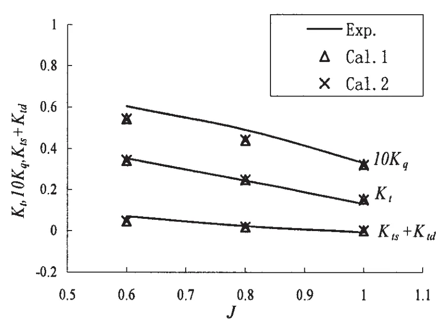
Fig.3 Comparison of experimental and calculational results of ducted propeller when stators set at 3°
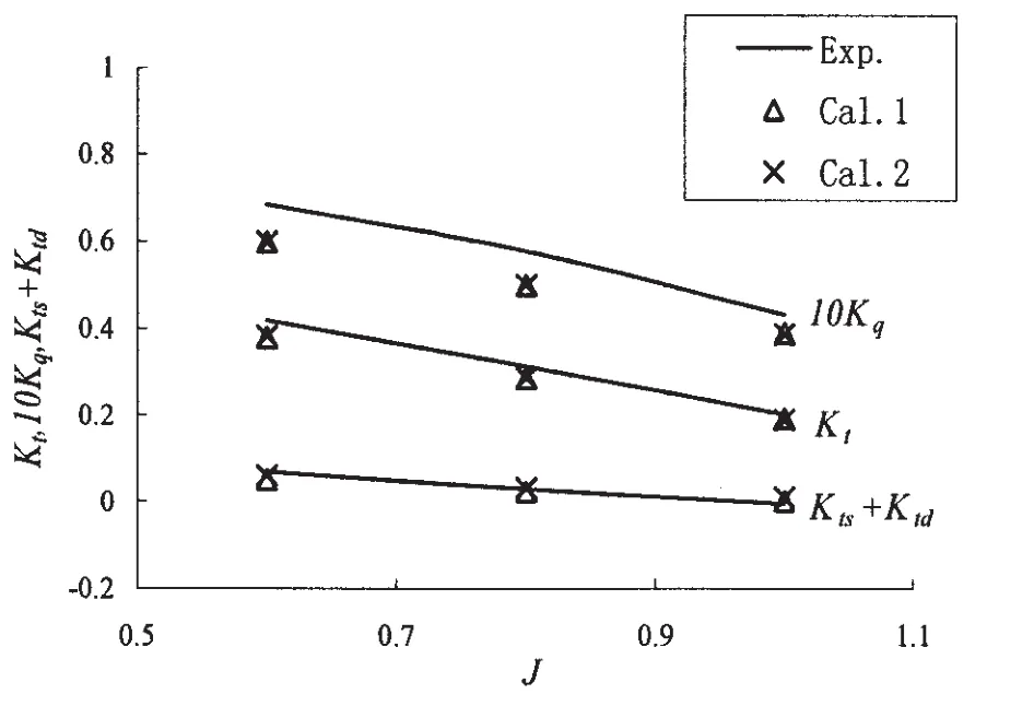
Fig.4 Comparison of experimental and calculational results of ducted propeller when stators set at 9°
In Fig.3 and Fig.4,Exp.is the experiment value shown in Ref.[2],Cal.1 results indicate that the stators and duct are considered as a whole.Cal.2 results denote that duct and stators were computed separately by the iterative induced velocity.It can be seen from figures that the thrust coefficients of Cal.1 and Cal.2 agree with the experiment results well,but the torque coefficients have some difference.The reason is:first,the torque of propeller is influenced by the viscidity greatly,but the surface panel method is a potential flow method in which the fluid is assumed to be inviscid.Second,the wake model used here is linear.Fig.3 and Fig.4 also show that the results of Cal.1 and Cal.2 are very similar.However,the calculation speed of Cal.1 is more quick than Cal.2.Cal.1 needs about 15 minutes while Cal.2 needs nearly 100 minutes when the total results are convergent at one advance coefficient.
4 Conclusions
The performance of a ducted propeller with stators at different stator angles are computed based on surface panel method.During the calculation,the duct and stators are considered as a whole,and the interaction between the propeller and the stator-duct was iterated by induced velocity.At the same time,the method which the propeller,duct and stators were computed separately by the iterative induced velocity is also applied.The comparison of the two methods results and experimental values shows that these two methods are effective for predicting the steady performance of ducted propeller with stators,but the method considering the stators and duct as a whole can save much calculating time than the other.
[1]Liu Wenfeng,Hu Yuli.Analysis of construction principle and characteristics of pump-jet for underwater integrated motor propulsor[J].Torpedo Technology,2007,15(6):5-10.
[2]Hughes M J,Kinnas S A.An analysis method for a ducted propeller with pre-swirl stator blades[C]//Proceedings of Propellers&Shafting’91 Symposium.Virginia Beach:SNAME,1991:15-1-15-8.
[3]Kinnas S A,Hsin C Y,Keenan D P.A potential based panel method for the unsteady flow around open and ducted propellers[C]//18th ONR.Ann Arbor,Michigan,1990:21-38.
[4]Kawakita C.Hydrodynamic analysis of a ducted propeller in steady flow using a surface panel method[J].The West-Japan Society of Naval Architects,1992,84:11-22.
[5]Wang Guoqiang,Yang Chenjun.Hydrodynamic performance prediction of ducted propeller with stators[J].Journal of Ship Mechanics,1999,3(3):1-7.
[6]Zhang J H,Wang G Q.Prediction of hydrodynamic performances of ducted controllable pitch propellers[J].Journal of Ship Mechanics,2002,6(6):18-27.
[7]Liu xiaolong,Wang guoqiang,A potential based panel method for prediction of steady performance of ducted propeller[J].Journal of Ship Mechanics,2007,11(3):333-340.
[8]Su Yumin,Huang Sheng.Theory of ship propeller[M].Harbin:Harbin Engineering University Press,2003:159-163.
[9]Cai Haopeng,Su Yumin,Li xin,et al.Using the surface panel method to predict the steady performance of ducted propellers[J].Journal of Marine,2009,8(4):275-279.
[10]Su Yumin,Ikehata Mitsuhisa,Kai Hisashi.Numerical analysis of the flow field around marine propellers by surface panel method[J].Ocean Engineering,2002,20(3):44-47.

- 船舶力学的其它文章
- Experimental Study of the Motion Responses of a Large Mooring(LNG)Ship in the Waves with Grand Period
- CLSVOF Method for Violent Sloshing with Impact Load in Tanks under Shallow Water Depth
- Experimental Research on Hydrodynamic Characteristics of Propeller in Waves
- Research on Method for Optimization Design of Riblets Angle based on CFD Techniques
- Online Prediction of Ship Rolling based on Varying Parameters LSSVM
- In-line Dynamic Characteristic of a Circular Cylinder under Vortex-induced Vibration