
Research on Method for Optimization Design of Riblets Angle based on CFD Techniques
2012-12-13 02:56ZHUQifengSONGBaoweiHUANGQiaogao
船舶力学 2012年9期
ZHU Qi-feng,SONG Bao-wei,HUANG Qiao-gao
(College of Marine,Northwestern Polytechnical University,Xi’an 710072,China)
1 Introduction
V-shaped riblets have better drag-reducing effect,which can save energy source in the fluid transport,aviation and maritime areas.This drag-reducing V-shaped riblers have been practically applied abroad,for example,in the Summer Olympic Games of 1984,the U.S.rowing team successfully applied films with a riblets surface structure at the bottom of the row boats,70%of the testing Airbus A320 surface were covered with the riblets surface structured film,which saved oil by 1%~2%.
This V-shaped riblers drag-reducing is a turbulent drag reduction technology,which draws great attention from the scientists because of its better drag-reducing effect.Walsh[1-3]had done great work on V-shaped riblets experiment,and found that the symmetric riblets have the best drag reduction effect.The numerical simulation studies had been done by Liu as well as Hu[4-6].Lun-chini et al[7]had carried out the primal studies of the V-shaped riblets optimization design.Wu et al[8]had carried out the research on the optimum angle of the V-shaped riblets in the channel based on the former achievement and some assumptions.
Firstly,this paper carried out the studies of V-shaped riblets numerical simulation based on CFD,then,using iSIGHT software,structure parameters generated program of riblets surface,hydrodynamic numerical simulation software GAMBIT and FLUENT were integrated,with optimization design technology and the numerical simulation technology,an optimization design method of V-shaped riblets angle was explored based on CFD technology,which provides a new direction for the V-shaped riblets optimization design problem.
2 Numerical method
2.1 RNG k-ε turbulence model
Large data show that riblets surface reaches better drag-reducing effect in the turbulent state.Therefore,during the numerical simulation period of the riblets surface,the model should be in fluid turbulence state[9-10].This paper adopts Reynolds-average Navier-Stokes equation and RNG k-ε turbulence model.This calculation method can provide more precise numerical solution of the flow field,but with large calculating amount.The specific mathematical model of this method is as follows:
Continuity equation:

Reynolds-average Navier-Stokes equation:

The Reynolds-average Navier-Stokes equation is basically the same as the transient NS equation,but the appearance ofrepresenting the turbulent effect causes the number of unknown quantities to exceed the number of equations.In order to solve this problem,the turbulent model should be brought.In this paper,the RNG k-ε turbulence model is adopted,which is the modified version of standard k-ε turbulence model.This turbulence model can deal with high strain rate and flow with large bending degree of streamline better[11-12].The turbulence model[13]can be expressed as follows:
Turbulent kinetic energy(k equation):

Turbulent dissipation rate(ε equation):

2.2 Reliability analysis of the RNG k-ε model
In order to verify the reliability of this numerical simulation using RNG k-ε turbulent model,the turbulent frictional resistance coefficient of smooth plate is calculated by this method.The calculation results are compared with the turbulent frictional resistance coefficient calculated by Prandtl turbulent boundary layer formula,and the error ratio by this numerical method is listed in Tab.1.
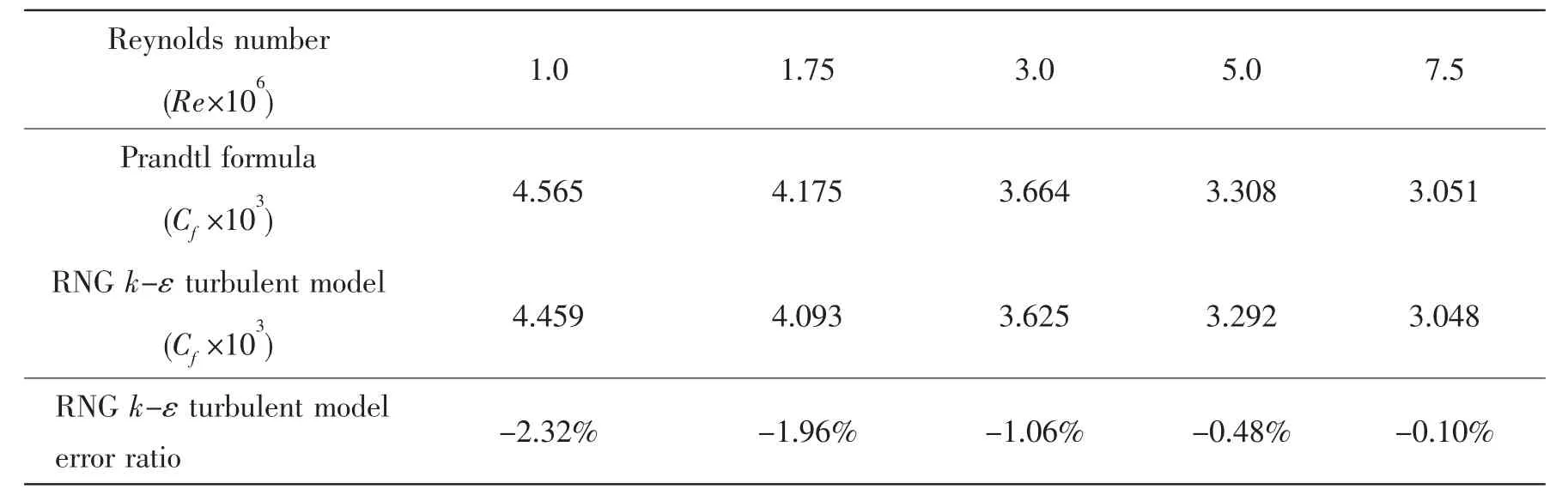
Tab.1 Comparison of results between RNG k-ε turbulent model and Prandtl formula
The Reynolds numbers used in the calculation are:Re=1×10⁶,Re=1.75×10⁶,Re=3×10⁶,Re=5×10⁶,and Re=7.5×10⁶.The expression of Prandtl turbulent boundary layer formula is:Cf=0.074Re-1/5,Re=ρνL/μ.
As shown in Tab.1,the max error ratio with the 5 different Reynolds numbers is 2.32%,the calculational result by RNG k-ε turbulent model is in perfect accord with the result calculated by Prandtl turbulent boundary layer formula,which shows that the RNG k-ε turbulent model can simulate the turbulent boundary layer very well.
2.3 Calculation domain and grid generation
After repeated testing calculation,it shows that the impacted region of viscous flow field mainly concentrates on 10 times or less the size of riblets surface.Taking the computer’s ability into account,the paper selects a two-dimensional space with riblets flowed surface as the computational domain.In order to reduce the grids amount and computation,in the calculation domain,the width of the rectangular computational domain is Ly=100*s,which would minimize the mutual interference of the flow field.The middle part of the under wall is riblets surface,with its length 20 times size of the riblets structure(L=20*s).In order to avoid the effects of the entrance and the exit,a flat section 30 times size of the riblets surface is retained in both entrance and exit.Fig.1 is the final calculation domain.
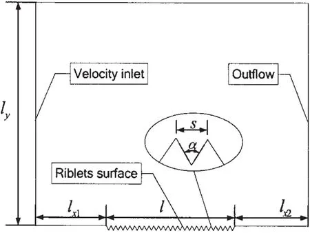
Fig.1 Calculation region
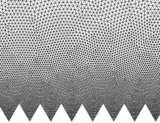
Fig.2 Mesh generation on the riblets surface
In this paper,the computational grid is generated by the method of limited volume discretion.In view of its special shape and the existence of cusps on riblets surface,this paper uses unstructured triangular grid to fill calculation domain.Considering the complexity of regional flows on the riblets surface,in order to improve the calculation accuracy and save computing resources,the defined size function method is applied in the near wall region to make the grid around the riblets surface turn intensive and gradually become sparse outward.Fig.2 is the partial enlarged drawings around the riblets surface.
2.4 Solution conditions
In order to simulate the micro flow field of the riblets surface and improve the calculation accuracy,the detailed setting is as follows:
Solver:steady-state segregated two-dimensional implicit solver.
Turbulence equations:RNG k-ε turbulence model.
Fluid medium:water,density of 998.2 kg/m3,dynamic viscosity coefficient is 0.001 003 Pa·s.
Boundary conditions:the entrance is velocity inlet with flow rate 5 m/s,along the x-axis;the exit is outflow.The riblets surface boundary condition is the no-slip boundary.
Discrete equation method:pressure-correction method uses Numerical SIMPLEC calculation method[15],and the discrete method of parameters uses the second-order accuracy upwind scheme.
Convergence criteria:the continuity equation residual is set to 1e-4 and 1e-5 for others.
3 Optimization design
3.1 Model of optimization design
By comparing the drag of riblets surface and the smooth surface,this paper evaluates the drag-reducing effect by relative drag-reducing amount.The total drag of the riblets surface contains viscous drag and pressure drag,while for the smooth surface;it only contains viscous drag,and no pressure drag.The relative amount of drag reduction is defined as follows:

where dfis relative drag-reducing amount;F is total drag of smooth surface;F1is total drag of riblets surface.
The relative amount of drag reduction can clearly express the drag-reducing effect of the riblets surface,therefore the relative amount of drag reduction is selected as the objective function.As this paper mainly studies how the size of bottom angle of the riblets surface impacts the riblets surface,the selected variable is the bottom angle(unit:°)of the riblets surface structure.With comprehensive consideration,the numerical range of the variables is 30~150,the eventual mathematical model of the optimal design is as follows:
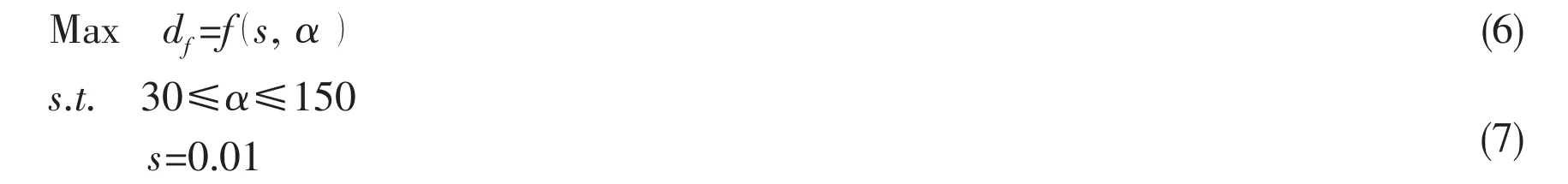
3.2 Optimization process
Per the requirements,the generated program GoucaoCreat.exe of the riblets surface structure parameters is made.Introduce the file shape.txt into GAMBIT,set the model,generate and output the Grid file.FLUENT reads the grid file,gets the solution through setting the parameters.iSIGHT analyzes the hydrodynamics report file trans.out generated by solution obtained from FLUENT,and outputs the total drag of riblets surface.Through comparison with the total drag of the smooth surface,the relative amount of drag reduction is calculated out and output as the objective function.The process diagram of the GoucaoCreat.exe program,grid division software GAMBIT and FLUENT integrated by iSIGHT is shown in Fig.3.
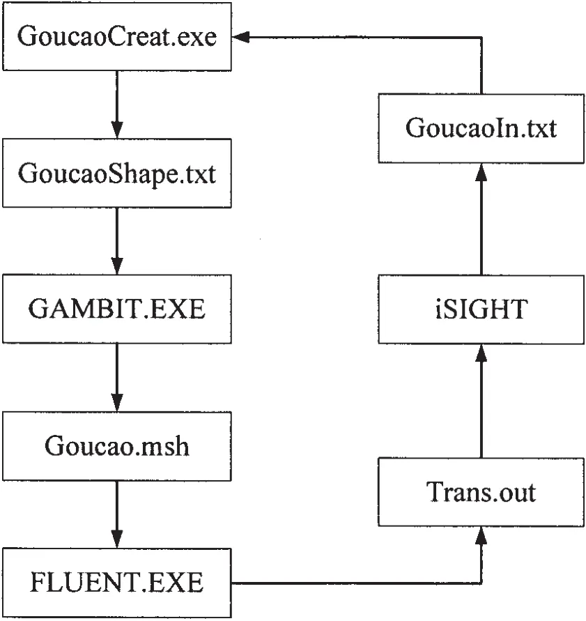
Fig.3 Optimization process chart
3.3 Optimization algorithm
In allusion to the problem for optimal design of riblets angle,a combined optimization program is developed,which can avoid sinking in the plight of the partial optimized solution.This combined optimization program is as follows:
Step one:the Adaptive Simulated Annealing algorithm(ASA)is selected as the first step of the optimization algorithm,which is a stochastic optimization method established by the simulation of the metal annealing mechanism.It is used for global search optimization,which searches the global scope in the design space.It would initially determine the optimal design point.
Step two:Sequential Quadratic Programming algorithm(Sequential Quadratic Programming-SQP)is used as the second step of the optimization algorithm.It is a gradient type optimization algorithm,which is one of the best algorithms to solve today’s smooth nonlinear programming problems.It maintains a local super-convergence while having a global convergence.SQP algorithm can solve the shortcomings of low accuracy.
4 Results analysis
As an optimization software framework,iSIGHT provides the optimal design interface,which allows designers to easily describe their optimization design problem in it.According to this mathematical model for optimal design,the optimization problem described in iSIGHT interface is shown in Fig.4,data transfer process in the iSIGHT integrating interface is described in Fig.5.

Fig.4 Description of optimization model in iSIGHT
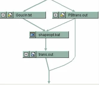
Fig.5 Data transfer process
With optimization design of variables through the combined optimal design program of ASA+SQP,and the 321 steps of iterative computation,this paper ultimately obtains the optimal angle of the riblets surface.
Tab.2 is the comparison of relevant parameters before and after optimization design.
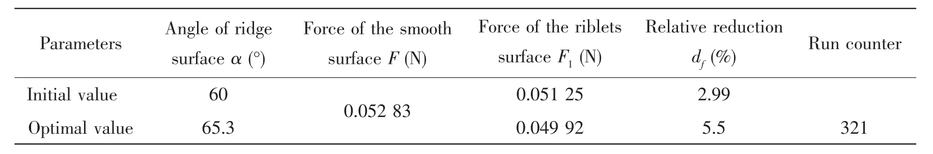
Tab.2 Comparison of relevant parameters before and after optimization design
From the table above,it can be seen that with optimization design,the angle of the riblets surface becomes large,the total drag reduces,the relative amount of drag reduction increases,reaching 5.5%,and a very remarkable drag reduction effect is achieved,which achieves the optimization design of riblets angle.
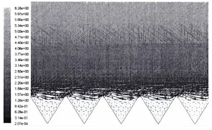
Fig.6 Vector graph of riblets surface
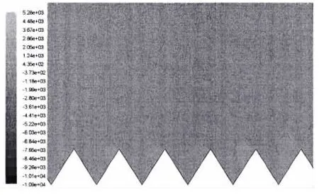
Fig.7 Pressure distribution of riblets surface
Fig.6 is the pressure contours near the drag-reducing riblets surface.Fig.7 is the velocity vector distribution graph near the riblets surface.
As shown in Fig.6,a strong vortex is formed in the drag-reducing riblets trough,which is the second vortex.The second vortex maintains a steady state in the trough,its form is strengthened and stabilized,which makes the flow occur separation.Because of the separation,a row of rolling is equivalent to exist between fluid and reblets,which makes friction from sliding friction into rolling friction.The secondary vortex’s existence reduces the friction between fluid and riblets,and it plays a better drag-reducing effect.
As can be seen from Fig.7,a series of small-scale distribution area with slightly higher pressure is formed at the left side of the riblets spire,which is the root for riblets pressure drag.After the optimization design,the small-scale distribution area has been reduced,which will reduce the pressure drag for riblets.
5 Conclusions
This paper puts forward and realized the optimization design method of drag-reducing riblets angle based on CFD technology,which integrates the numerical simulation technology and optimization design technology.Using optimization software iSIGHT,structure parameters generated program of riblets surface,hydrodynamic numerical simulation software GAMBIT and FLUENT were integrated,which achieves the optimization design of riblets angle.Through the comparison of the results before and after optimization design,it can be found that after optimization design,the relative amount of the riblets surface increased,the drag-reduction effect is obvious,and the drag characteristics of riblets are optimized.In addition,by analyzing the drag characteristics of smooth plate and riblets,as well as analyzing the changing characteristics of riblets surface before and after optimization design,the conclusions can be obtained as follows:
(1)The existence of riblets changed the flow field near the smooth plate,the pressure drag was produced,and the secondary vortex was formed in the drag-reduction riblets trough.As a result,the flow occurred separation,which played a role in reducing the drag.
(2)The secondary vortex’s form is dependent with riblets angle,and its form was in the optimal state after optimization design.Therefore,the total drag of the riblets decreased,the relative amount of drag-reduction increased,and the drag-reduction effect was significantly improved.
(3)The optimization design of riblets angle was achieved with the method presented in this paper,this optimization method based on CFD technology will be the main direction for the riblets optimization research in future.
[1]Walsh M J.Riblets as a viscous drag reduction technique[J].AIAA Journal,1983,21(4):485-486.
[2]Walsh M J.Turbulent boundary layer drag reduction using riblets[R].AIAA Paper 82-0169,1982.
[3]Walsh M J,Lindemann A M.Optimization and application of riblets for turbulent drag reduction[R].AIAA Paper 84-0347,1984.
[4]Liu Zhihua,Dong Wencai,Xia Fei.The effects of the tip shape of V-groove on drag reduction and flow field characteristics by numerical analysis[J].Journal of Hydrodynamics(ser.A),2006,21(2):223-231.
[5]Hu Haibao,Song Baowei,Du Xiaoxu,Ma Ji.Research on numerical computation of near-wall fluid field on grooved surface[J].Fire Control and Command Control,2008,33(4):54-56.
[6]Pan Guang,Guo Xiaojuan,Hu Haibao.Numerical simulation of semicircular traveling wave surface and study on its dragreduction mechanism[J].Journal of System Simulation,2006,18(11):3073-3074.
[7]Luchini P,Pozzi A.Computation of three-dimensional stokes flow over complicated surfaces(3d riblets)using a boundary-independent grid and local corrections[C]//10th European Drag Reduction Meeting.Berlin,l997.
[8]Wu Yufeng,Long Ju,Zhang Xiaoli.Research on the optimum angle of the V-shaped riblet in the channel[J].Journal of Sichuan University of Science and Technology,2004,23(3):80-81.
[9]Liu Zhanyi,Song Baowei,Hu Haibao,Huang Qiaogao,Huang Mingming.Experiment investigation on the drag-reduction characteristics above riblet surface in wind tunnel[J].Journal of Experimental Mechanics,2008,23(5):469-474.
[10]Pan Guang,Huang Qiaogao,Hu Haibao,Liu Zhanyi.Numerical simulation research about the drag reduction over riblet structure with different space of gyroidal object[J].Acta Aerodynamica Sinica,2010,28(3):267-271.
[11]Huang Lumeng,Liou William W.Assessment of two low-Reynolds-number k-ε models in turbulent boundary layers with surface roughness[R].AIAA-2007-1448.
[12]Johnson D,Subramanian Chelakara S.Numerical study of a scaling parameter for turbulent boundary layer with large roughness[R].AIAA-2007-1451.
[13]Xu J G.Algebraic stress model with RNG equation for simulating confined strongly swirling turbulent flows[J].Journal of Thermal Science,2001,15(1):14-19.
[14]Zhang Zixiong,Dong Zengnan.Viscosity hydrodynamics[M].Beijing:Tsinghua University Press,1998.
[15]Wang Fujun.Computational fluid dynamics analysis[M].Beijing:Tsinghua University Press,2004.

- 船舶力学的其它文章
- Experimental Study of the Motion Responses of a Large Mooring(LNG)Ship in the Waves with Grand Period
- CLSVOF Method for Violent Sloshing with Impact Load in Tanks under Shallow Water Depth
- A New Method for Predicting the Steady Performance of Ducted Propeller with Stators
- Experimental Research on Hydrodynamic Characteristics of Propeller in Waves
- Online Prediction of Ship Rolling based on Varying Parameters LSSVM
- In-line Dynamic Characteristic of a Circular Cylinder under Vortex-induced Vibration